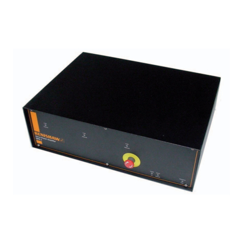
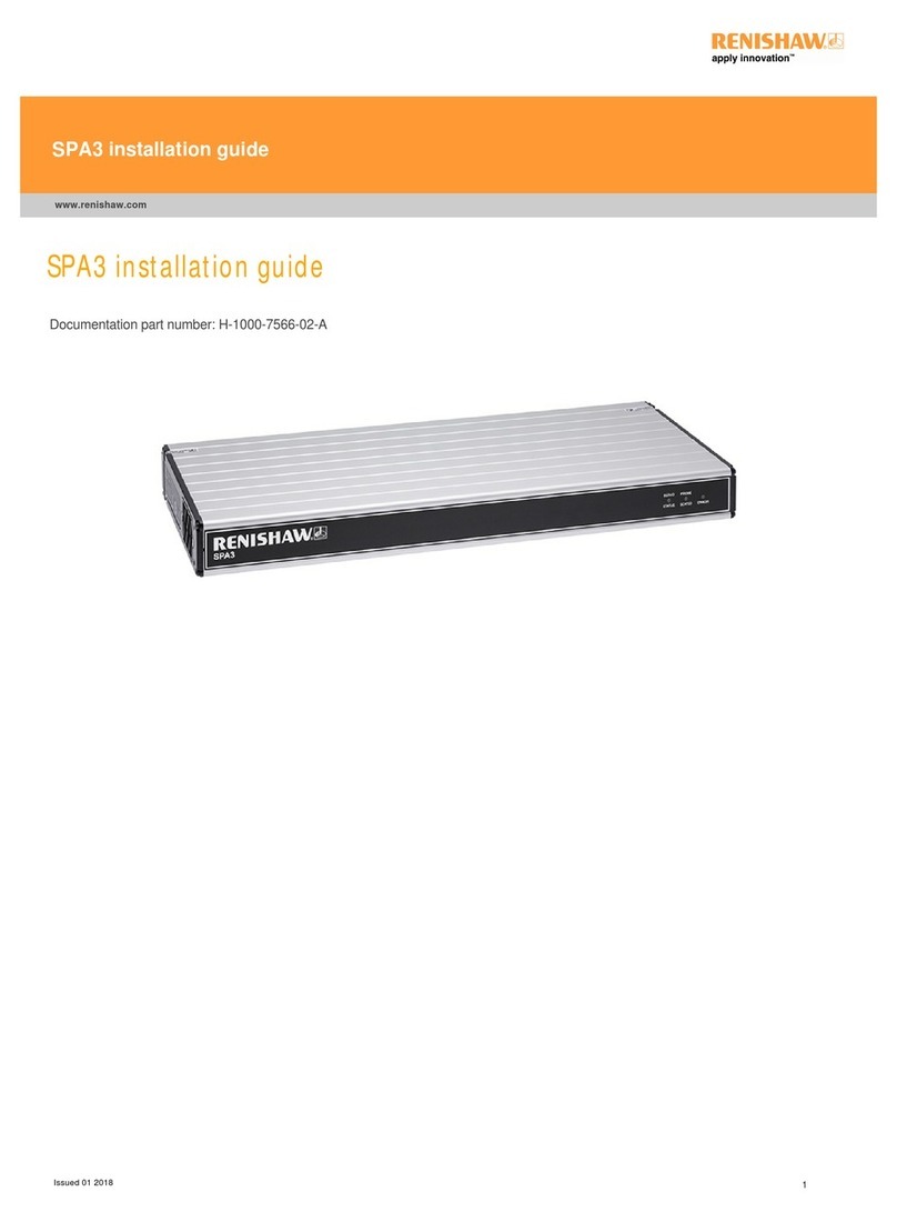
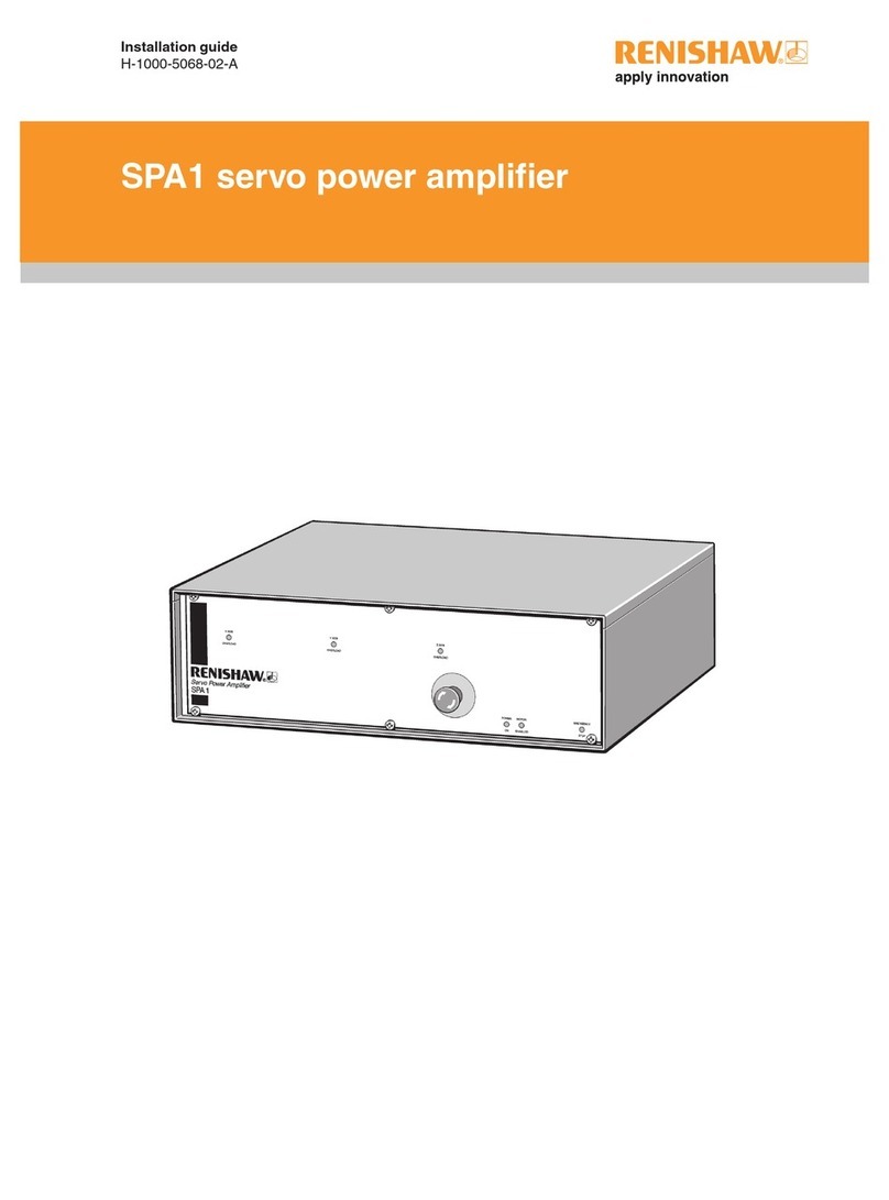
Renishaw SPA1 User manual

Installation guide
H-1000-5068-05-A
SPA1 servo power amplifier

© 2003 - 2006 Renishaw plc. All rights reserved.
Renishaw® is a registered trademark of Renishaw plc.
This document may not be copied or reproduced in whole or in
part, or transferred to any other media or language, by any means,
without the prior written permission of Renishaw.
The publication of material within this document does not imply
freedom from the patent rights of Renishaw plc.
Disclaimer
Considerable effort has been made to ensure that the contents of
this document are free from inaccuracies and omissions. However,
Renishaw makes no warranties with respect to the contents of
this document and specifically disclaims any implied warranties.
Renishaw reserves the right to make changes to this document
and to the product described herein without obligation to notify any
person of such changes.
Trademarks
RENISHAW® and the probe emblem used in the RENISHAW logo
are registered trademarks of Renishaw plc in the UK and other
countries.
apply innovation is a trademark of Renishaw plc.
All brand names and product names used in this document are
trade names, service marks, trademarks, or registered trademarks
of their respective owners.
Renishaw part no: H-1000-5068-05-A
Issued: 12 2006

SPA1
Installation guide

2
FCC
Information to user (FCC section 15.105)
This equipment has been tested and found to comply with the limits for a class A digital device, pursuant
to part 15 of the FCC rules. These limits are designed to provide reasonable protection against harmful
interference when the equipment is operated in a commercial environment. This equipment generates,
uses and can radiate radio frequency energy and, if not installed and used in accordance with the
installation manual, may cause harmful interference to radio communications. Operation of this equipment
in a residential area is likely to cause harmful interference, in which case you will be required to correct the
interference at your expense.
Information to user (FCC section 15.21)
The user is cautioned that any changes or modifications not expressly approved by Renishaw plc or
authorised representative could void the user’s authority to operate the equipment.

3
EC declaration of conformity
The SPA1 has been manufactured in conformity with the following standards:
BS EN 61326:1998 Electrical equipment for measurement, control and laboratory use –
EMC requirements.
Immunity to Annex A - industrial locations.
Emissions to class A (non-domestic) limits.
BS EN 60204-1:1998 Safety of machinery – Electrical equipment of machines.
Part 1: General requirements.
and that it complies with the requirements of the following EC Directives (as amended):
89/336/EEC – Electromagnetic compatibility (EMC).
73/23/EEC – Low voltage.

4
Care of equipment
Renishaw probes and associated systems are precision tools used for obtaining precise measurements
and must therefore be treated with care.
Changes to Renishaw products
Renishaw reserves the right to improve, change or modify its hardware or software without incurring any
obligations to make changes to Renishaw equipment previously sold.
Warranty
Renishaw plc warrants its equipment for a limited period (as set out in our Standard Terms and Conditions
of Sale) provided that it is installed exactly as defined in associated Renishaw documentation.
Prior consent must be obtained from Renishaw if non-Renishaw equipment (e.g. interfaces and/or cabling)
is to be used or substituted. Failure to comply with this will invalidate the Renishaw warranty.
Claims under warranty must be made from authorised service centres only, which may be advised by the
supplier or distributor.

5
References and associated documents
It is recommended that the following documentation is referred to when installing the SPA1.
Renishaw documents
Documentation supplied on Renishaw UCC software CD.
Document number Title
H-1000-5056 UCC1 installation guide
H-1000-5057 UCC programmer’s guide
H-1000-5058 RENICIS user’s guide
H-1000-5067 MCU1 installation and user’s guide
H-1000-5223 UCC2 installation guide
H-1000-5227 UCC1 and UCC2 servo tuning user’s guide
External documents
National and international standards including the following may be applicable to the finished machine or
installation:
EN 292-2:1991 (Safety of machinery - Basic concepts, general principles for design - Part 2: Technical
principles and specifications.
EN (IEC) 60204-1:1997 (Safety of machinery - Electrical equipment of machines -
Part 1: General requirements).
Document number Title
0470-0005 User’s guide, ‘Mini Maestro™’ drive

6 Safety
Safety
Electrical requirements
The SPA1 is powered from the a.c. mains supply via an IEC 320 connector. The operating voltages of the
unit are as follows:
90 – 264 V ac 47 – 63 Hz 600 W maximum
This equipment must be connected to a protective earth conductor via a three core mains (line) cable. The
mains plug shall be inserted only into a socket outlet provided with a protective earth contact. The
protective earth contact shall not be negated by the use of an extension cable without protective
conductor.
An earth stud is provided to allow bonding of the CMM metal parts to the protective earth.
WARNING: Any interruption of the protective conductor may make the equipment dangerous.
Make sure that the grounding requirements are strictly observed.
Environmental requirements
The following environmental conditions comply with (or exceed) BS EN 61010-1:1993
Indoor use IP30 (no protection against water)
Altitude up to 2000 m
Operating temperature 0 °C to +50 °C (local to SPA2)
Storage temperature -10°C to +70°C
Relative humidity 80% maximum (non-condensing) for temperatures up to +31 °C.
Linear decrease to 50% at +40 °C
Transient overvoltages Installation category II
Pollution degree 2
NOTE: If a higher IP rating is required, following a risk assessment by the installer of the equipment, an
additional external enclosure will be required to house the SPA1.
!

System description 7
Contents
1System description .................................................................................................................................. 9
1.1 SPA1 kit components .................................................................................................................... 9
1.1.1 SPA1 kit for UCC1 control (A-1333-0008) ...........................................................................9
1.1.2 SPA1 kit for UCC2 and UCClite control (A-5121-0008).......................................................9
1.2 SPA1 accessories ....................................................................................................................... 10
1.2.1 Service kits.........................................................................................................................10
1.2.2 Replacement SPA drives ...................................................................................................10
1.3 SPA1 system layout .................................................................................................................... 11
1.4 Simplified SPA1 and UCC2 layout .............................................................................................. 12
1.5 Simplified SPA1 and UCClite layout............................................................................................ 13
2Front panel description .......................................................................................................................... 14
2.1 Axis overload............................................................................................................................... 14
2.2 Emergency stop LED .................................................................................................................. 14
2.3 Motor enabled ............................................................................................................................. 15
2.4 Power .......................................................................................................................................... 15
2.5 Emergency stop button ............................................................................................................... 15
3Rear panel description........................................................................................................................... 16
3.1 Emergency stop connector.......................................................................................................... 17
3.1.1 Connector...........................................................................................................................17
3.1.2 Pin-outs..............................................................................................................................17
3.2 Machine I/O connector ................................................................................................................ 17
3.2.1 Connector...........................................................................................................................17
3.2.2 Pin-outs..............................................................................................................................17
3.3 Servo power amplifier connector.................................................................................................18
3.3.1 Connector...........................................................................................................................18
3.3.2 Pin-outs..............................................................................................................................18
3.4 Motor connector .......................................................................................................................... 19
3.4.1 Connector...........................................................................................................................19
3.4.2 Pin-outs..............................................................................................................................19
4Installing the SPA1 ................................................................................................................................ 20
4.1 Preparation of SPA1 service pack............................................................................................... 20
4.1.1 Motor connectors ...............................................................................................................20
4.1.2 20 KΩpotentiometer on DIL header ..................................................................................21
4.1.3 20 KΩpotentiometer on 150 mm wire ...............................................................................21
4.1.4 Emergency stop .................................................................................................................22
4.1.5 Machine I/O connector.......................................................................................................22
4.2 Setting of the motor voltage ........................................................................................................ 23
4.3 Accessing SPA drives ................................................................................................................. 24
4.4 Functions of the SPA drive potentiometers ................................................................................. 25
4.4.1 Ramp..................................................................................................................................25
8System description
4.4.2 Derivative .......................................................................................................................... 25
4.4.3 Proportional....................................................................................................................... 25
4.4.4 Zero offset ......................................................................................................................... 25
4.4.5 Max speed......................................................................................................................... 25
4.5 Adjusting the SPA drives............................................................................................................. 26
4.5.1 Max speed adjustment ...................................................................................................... 26
4.6 Adjustment of the inductance of the motor drive system............................................................. 28
5System interconnection diagrams.......................................................................................................... 30
5.1 Cable connections....................................................................................................................... 30
5.1.1 Emergency stop cable....................................................................................................... 30
5.1.2 SPA cable ......................................................................................................................... 31
5.1.3 Machine I/O cable ............................................................................................................. 32
6Maintenance .......................................................................................................................................... 33
7Testing and verification.......................................................................................................................... 34
8Revision history ..................................................................................................................................... 35

System description 9
1 System description
The servo power amplifier (SPA1) unit is a 3-axis variable speed drive for permanent magnet DC servo
motors, designed for use with Renishaw universal CMM controllers (UCC1 or UCC2).
The unit contains three proprietary servo power amplifiers, contactor circuitry and a power supply.
1.1 SPA1 kit components
Two SPA1 kits are available, the contents of these kits being dependent on whether a UCC1 or UCC2
controller is incorporated into the system. These kits contain the following components:
SPA1 kit for UCC1 control A-1333-0008
SPA1 kit for UCC2 control A-5121-0008
All the necessary interconnection connection cables are supplied as components of the appropriate
SPA1 kit.
1.1.1 SPA1 kit for UCC1 control (A-1333-0008)
This kit contains three connection cables as listed below:
•MCU (joystick) daughtercard ESTOP connector to UCC1 comms CH1 connector for emergency
stop signal.
•SPA1 ‘SPA’ connector to UCC1 ‘servo power amplifier’ connector.
•SPA1 ‘machine I/O’ connector to UCC1 ‘machine I/O connector’, incorporating an additional connector
for interconnection of other system signals.
1.1.2 SPA1 kit for UCC2 and UCClite control (A-5121-0008)
This kit contains a signal connection cable whose function is to connect the SPA1 ‘SPA’ connector to
UCC2 ‘servo power amplifier’ connector.
NOTE: The cable included in this kit is not compatible with the UCC1 system, connection of this cable to
a UCC1 will cause damage to the UCC1.

10 System description
1.2 SPA1 accessories
1.2.1 Service kits
Two SPA1 service kits are available, the contents of these kits being dependant on whether a UCC1 or
UCC2 controller is incorporated into the system. These kits contain the following components:
SPA1 service kit for UCC1 control A-1333-0017
SPA1 service kit for UCC2 control A-5121-0029
1.2.1.1 SPA1 service kit for UCC1 control (A-1333-0017)
This SPA1 service kit contains the following components that will assist in the connection of the SPA1 to a
UCC1 controlled system:
•3 off motor connectors including backshells
•6 off power pins for motor connectors (7W2)
•4 off DIL headers
•4 off 20 KΩmulti-turn potentiometers
•300 mm length of wire
•1 off 37-way D connector including backshell for machine I/O connection *
•1 off 9-way D connector including backshell for emergency stop connection
1.2.1.2 SPA1 service kit for UCC2 control (A-5121-0029)
This SPA1 service kit contains the following components that will assist in the connection of the SPA1 to a
UCC2 controlled system:
•3 off motor connectors including backshells
•6 off power pins for motor connectors (7W2)
•4 off DIL headers
•4 off 20 KΩmulti-turn potentiometers
•300 mm length of wire
•1 off 44 way D connector including backshell for machine I/O connection
•1 off 9-way D connector including backshell for emergency stop connection
1.2.2 Replacement SPA drives
If required, for support purposes, replacement SPA drives (part number P-MC10-0001) can be ordered
from Renishaw.

System description 11
1.3 SPA1 system layout
Figure 1 – Simplified SPA1 and UCC1 system layout
MCU1
UCC1
SPA1

12 System description
1.4 Simplified SPA1 and UCC2 layout
Figure 2 – Simplified SPA1 and UCC2 system layout
MCU1
UCC2
SPA1

System description 13
1.5 Simplified SPA1 and UCClite layout
Figure 3 – Simplified SPA1 and UCC2 system layout

14 Front panel description
2 Front panel description
Key
1. X axis overload indicator (refer to section 2.1)
2. Y axis overload indicator (refer to section 2.1)
3. Z axis overload indicator (refer to section 2.1)
4. Emergency stop indicator (refer to section 2.2)
5. Motor enabled indicator (refer to section 2.3)
6. Power indicator (refer to section 2.4)
7. Emergency stop button (refer to section 2.5)
Figure 3 - Front panel of the SPA1
2.1 Axis overload
There are a number of possible causes for this LED being lit, please refer to the Control Techniques™,
‘Mini Maestro™’ user guide supplied with the product.
2.2 Emergency stop LED
This LED is lit when the SPA1 is aware of an emergency stop being applied to the system. During normal
operation this LED is not illuminated.
1 2 3
76 5 4

Front panel description 15
2.3 Motor enabled
This LED is lit when the SPA1 servo amps are engaged.
2.4 Power
This LED is lit when there is a mains supply attached to the SPA1 unit.
2.5 Emergency stop button
A normal category ‘B’ emergency stop function is provided within this unit. It is the machine installer's
responsibility to add any additional emergency stop switches that the system requires.

16 Rear panel description
3 Rear panel description
Key
1. Emergency stop connector (refer to section 3.1)
2. Machine I/O connector (refer to section 3.2)
3. SPA connector (refer to section 3.3)
4. Z motor connector (refer to section 3.4)
5. Y motor connector (refer to section 3.4)
6. X motor connector (refer to section 3.4)
7. Mains power ON/OFF switch
8. Main power input via an IEC320 connector
9. Earth stud
10. Version number label
11. Serial number label
Figure 4 - Rear panel of the SPA1.
11 10 9
7
1 2 3 4 5 6
8

Rear panel description 17
3.1 Emergency stop connector
3.1.1 Connector
Figure 5 - ESTOP connector (view on face of socket or rear of plug)
3.1.2 Pin-outs
Pin number Description
1 Not connected
2 Not connected
3 Not connected
4 Not connected
5 Not connected
6 ESTOP A
7 ESTOP B
8 Not connected
9 Not connected
Shell Gnd
3.2 Machine I/O connector
3.2.1 Connector
Figure 6 - Machine I/O connector (view on face of socket or rear of plug)
3.2.2 Pin-outs
Pin number Description
1 Amplifier OK output
2 Not connected
3 Emergency stop output
4 Not connected
5 Motor contactor feedback output
6 Not connected
7 Not connected
8 Not connected
9 Not connected
Shell Shell and screen
51
6
9
2.0H X
51
6
9
2.0H X

18 Rear panel description
3.3 Servo power amplifier connector
3.3.1 Connector
Figure 7 – Servo power amplifier connector (View on face of socket / rear of plug)
3.3.2 Pin-outs
Pin number Function Description
1 +24 Vdc Provided for use on CMM status switches.
2 Contactor Input signal to control motor contactor
3 Not connected
4 Amp Control C Floating collector (amplifier enabling)
5 Amp Control E Floating emitter (amplifier enabling)
6 ESTOP A
7 ESTOP B
8 - Z command Differential input to CMM Z drive motor
9 + Z command Differential input to CMM Z drive motor
10 - Y command Differential input to CMM Y drive motor
11 + Y command Differential input to CMM Y drive motor
12 - X command Differential input to CMM X drive motor
13 + X command Differential input to CMM X drive motor
14 Not connected
15 Not connected
16 Command common Ref. line for power amplifier commands
17 Not connected
18 Not connected
19 Not connected
20 Not connected
21 Not connected
22 Mot cont F/B Motor contactor feedback output
23 Servo amps OK Amplifier OK output
24 ESTOP tripped
25 24 V return Common for dc supply and contactor signal
Shell Shell and screen
NOTE: Pin functions that are listed as not connected must not be connected.
13 1
25 14
2.0H X 8.6W
Other manuals for SPA1
1
Table of contents
Other Renishaw Amplifier manuals

Renishaw
Renishaw SPA3 User manual

Renishaw
Renishaw SPA2-2 User manual

Renishaw
Renishaw SPA3 User manual

Renishaw
Renishaw SPA3-2 600 W PSU User manual

Renishaw
Renishaw apply innovation SPA2 User manual

Renishaw
Renishaw H-1000-5068-02-A SPA1 s User manual

Renishaw
Renishaw SPA1 User manual

Renishaw
Renishaw SPA3-2 User manual

Renishaw
Renishaw SPA2-2 User manual
Popular Amplifier manuals by other brands

Audiodesign
Audiodesign ESX Quantum QS-TWO-ISO owner's manual

Blue Wave
Blue Wave BTA-1000 Install manual

BLACK STAR
BLACK STAR Artisan 212 owner's manual

Activeforever
Activeforever Pocketalker PKT D1 user manual

Hawg Wired
Hawg Wired MPS3004 installation guide

Four Audio
Four Audio PR4x1000-2-DSP user manual