SPECIFICATIONS
Continuous
power
output
(both
channels
driven
at
20
Hz
to
20
kHz)
**
T.H.D.
0.003%,
8
Q
Pe
ee
ee
105W
+
105W
*
T.H.D.
0.005%,
4
QD
vv
ccc
e
ccc
ec
er
sewccenne
160W
+
160W*
DIN
continuous
power
output
(both
channels
driven)
1
KHz,
T.H.D.
1.0%,
8
Qs
eeer
reece
ree
eeee
ees
120W
+
120W
1
KHz,
T.H.D.
1.0%,
4
Q
eereereereerereeennes
180W
+
180W
Power
bandwidth
0.05%,
BQ
ccvccvsevnvnanernrencnsecesenes
5
Hz—-
60
kHz*
Damping
factor
qa
kHz/20
Hz
to
20
kHz),
8
(oer
200/70
Dynamic
power
output
(on
EIA
dynamic
test
signal)
4
Q
/2
Q
See
eee
eee
ee
ee
ee
ee
230W/350W
Total
harmonic
distortion
**
;
20
Hz
to
20
kHz,
105W,
8
Q
ceceeecrsceeeeeeenees
0.003%
*
20
Hz
to
20
KHZ,
16OW,
4
Q
srcerreereceeeeeceees
0.005%
*
Inter-modulation
distortion
(at
rated
output)
--+++++++-+
0.003%
*
Input
sensitivity/impedance
PHONO
(MM)
+++
seeecceeeeeceeeee
ec
eeeeees
2.5
mV/50
kQ
PHONO
(MC)
orrceeeeeeeeeeeeeseeeeenees
0.2
mV/100
Q
CD,
TUNER,
LINE,
TAPE+-+-++++esseereeees
150
mV/50
k
Q
PHONO
overload
level
1
kHz,
T.H.D.
0.008%
(MM/MC)
---+++-++s++-
200
mV/19
mV
Output
level/fimpedance
TAPE
REC,
ADAPTOR
OUTPUT::---------
150
mV/2.2
kQ
Frequency
response
PHONO
(MM),
20
Hz
to
20
KHz
«++++++rsseseeeees
+0.2
dB
PHONO
(MC),
20
Hz
to
20
KHZ-++++
sss
ester
reer
+0.3
dB
CD,
TUNER,
LINE,
TAPE
(1
Hz
to
150
KHz)
--:--:-
ie
dB*
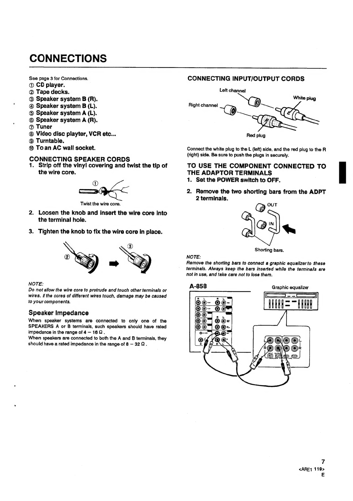
Be
sure
to
place
the
unit
on
a
level
surface
so
that
it
stands
firmly
on
all
its
feet.
If
wobbly,
adjust
by
attaching
the
supplied
cushion
spacers
to
one
or
more
feet.
10
<ARE1119>
E
Tone
control
(volume
control
set
at
-40
dB
position)
BASS
is
case
sce
don
thistena'de
cae
Gea
canine
+
8
dB
(100
Hz)
TREBLE
0
tin
8
tosices
ccaiee
dec
ee
sad
ee's
oiewers
+
8
dB
(10
kHz)
MUTING
28053
Seeds
os
eek
sareilaete
ic
esisem
sed
nots
gaeeets
0
Loudness
contour
(volume
control
set
at
-40
dB
position)
Saige
p
ors.
e:8'ae.0
9850'S
v:o,0
b
Sieleineee
+5
dB
(100
Hz)/+3
dB
(10
kHz)
Filter
(SUBSONIC)-+-
+++
+e
seer
sere
serene
ee
ee
17
Hz
(12
dB/oct.)
Signat-to-Noise
ratio
(IHF
short
circuit,
A
network)
PHONO
(MM,
5
mV
input/MC,
0.5
mV
input)
---
95
dB/77
dB*
CD,
TUNER,
LINE,
TAPE
Serre
ree
eee
ee
ee
ees
110
dB*
Signal-to-Noise
ratio
(DIN,
continuous
power/50
mW)
PHONO
(MM)
--+eerccee
reece
tet
eter
eee
eee
74
dB/65
dB*
CD,
TUNER,
LINE,
TAPE:--+----+
rs
eerr
reer
92
dB/68
dB
*
Power
Supply/Miscellaneous
Power
requirements
----++---++++++--
a.c,
220
Volts
~,
50/60
Hz
Power
consumption
:-+-+
sr
sesrr
cece
eect
c
reer
eee
eeeee
1,000W
Dimensions
-+-++++++eeererees
420
(W)
x
474
(D)
x
172
(H)
mm
Weight
(without
package)
+--+
ss
eeree
eet
e
eee
e
cence
eees
24.5
kg
Accessories
Operating
INStrUCTIONS
see
eee eer
tree
meee
were
n
ener
nrerenannnae
1
Cushion
spacer
set
s++rsrrecee
str
eee
crete
cece
eer
enreeeaeres
1
NOTE:
Specifications
and
design
subject
to
possible
modification
without
notice,
due
to
improvements.
*
Measured
with
the
DIRECT
switch
set
to
ON.
**
Measured
by
Audio
Spectrum
Analyzer.
POWER-CORD
CAUTION
Handle
the
power
cord
by
the
plug.
Do
not
pull
out
the
plug
by
tugging
the
cord
and
never
touch
the
power
cord
when
your
hands
are
wet
as
this
could
cause
a
short
circuit
or
electric
shock.
Do
not
place
the
unit,
a
piece
of
furniture,
etc.,
on
the
power
cord,
or
pinch
the
cord.
Never
make
a
knot
in
the
cord
or
tie
it
with
other
cords.
The
power
cords
should
be
routed
such
that
they
are
not
likely
to
be
stepped
on.
A
damaged
power
cord
can
cause
fire
or
give
you
an
electrical
shock.
Check
the
power
cord
once
in
a
while.
When
you
find
it
damaged,
ask
your
nearest
PIONEER
authorized
service
center
or
your
dealer
for
a
replacement.
.
MAINTENANCE
OF
EXTERNAL
SURFACES
*
Use
a
polishing
cloth
or
dry
cloth
to
wipe
off
dust
and
dirt.
*
When
the
surfaces
are
very
dirty,
wipe
with
a
sof
cloth
dipped
in
some
neutral
cleanser
diluted
five
or
six
times
with
water,
and
wrung
out
well,
and
then
wipe
again
with
a
dry
cloth.
Do
not
use
furniture
wax
or
cleaners.
Never
use
thinners,
benzine,
insecticide
sprays
and
other
chemicals
on
or
near
this
unit,
since
these
will
corrode
the
surfaces.
Published
by
Pioneer
Electronic
Corporation.
Copyright
©
1989
Pioneer
Electronic
Cor
poration.
All
rights
reserved.