Section 2: Important Background Information
What is Reverse Osmosis (RO)
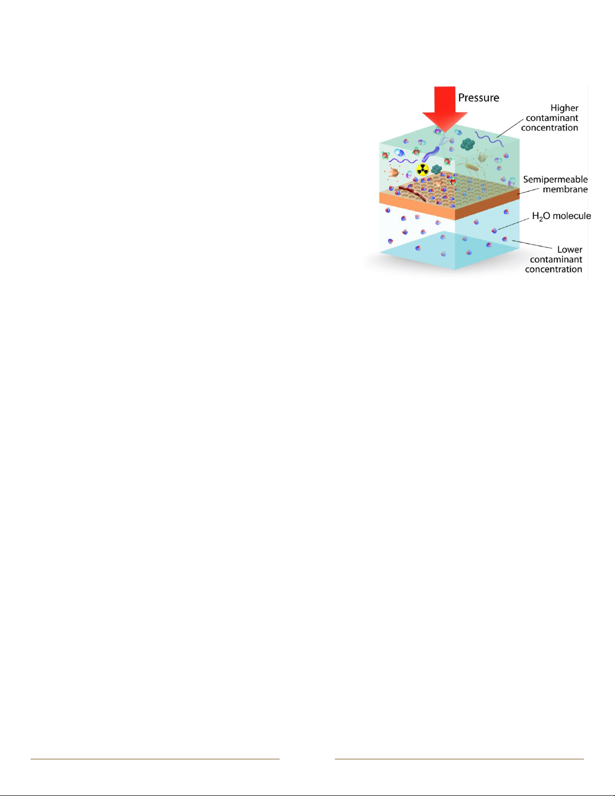
In the reverse osmosis process, water is forced under pressure through a
semi-permeable membrane to reduce the dissolved mineral content of the
water. The membrane allows water molecules to pass through, but
blocks/hinders the passage of dissolved substances and suspended particles.
This process reduces the levels of dissolved salts, minerals, and suspended
particles, while improving the taste, odor, and clarity of the water.
Certain contaminants found in water are measured as Total Dissolved Solids
(TDS). Unlike the more common standard filtration systems, reverse osmosis
systems divide the feed water into two streams: product water (“permeate”)
and drain/reject water (“concentrate”). The product water is the desired
outcome of the RO System –much cleaner and fresher tasting water! The
drain/reject water is vital for carrying away the dissolved salts, minerals, and
suspended particles. Unlike conventional filtration systems, the majority of
contaminants removed from your water are not held onto within the system,
but instead flushed away.
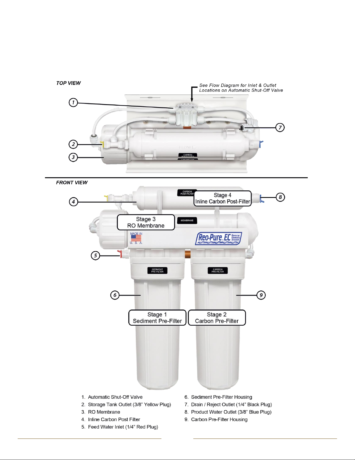
How the Reo-Pure™ RO System Works
Your new Reo-Pure™ RO System uses a combination of filtration technologies to reduce unwanted contaminants in a water supply.
The model you have chosen incorporates a series of stages to give you the most out of your RO System! For more information on
your unique model, please refer to the “Getting to Know Your System” section to better understand the different stages that work
together in making your RO System great!
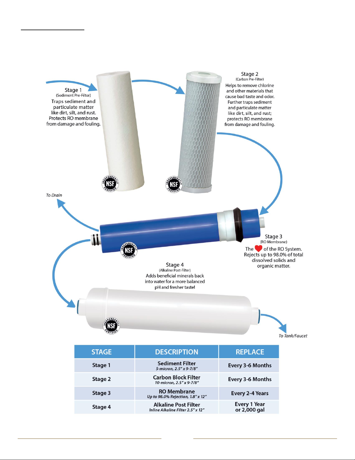
Importance of Pre-Filtration
Pre-treatment in a RO System is crucial. By running the feed water through the appropriate pre-filter, the RO membrane is protected
against permanent premature fouling damage. The filter cartridges in this system must be replaced on a regular basis to maintain
efficiency and to ensure high water quality. Any significant change in performance of the system should be investigated promptly to
avoid secondary damage or deterioration to other parts of the system.
Automatic Shut-Off Technology
Every RO System comes equipped with an automatic shut-off valve. This component closes when it senses that the storage tank is
full –immediately shutting off the water supply. As a result, the production of water is paused, and excess reject water is prevented
from draining.
Factors That Affect System Performance
Feed Water Temperature: The ideal water temperature for a RO System is 77°F. The quantity of product water produced increases
with higher water temperatures and decreases with lower water temperatures. Temperatures below 40°F can damage the
membrane, and temperatures above 90°F can cause rapid deterioration of the membrane.
Feed Water Pressure: The greater the water pressure, the better water quantity and quality the system will produce. Water
pressure of 65 psi is ideal.
Total Dissolved Solids (TDS): The higher the amount of dissolved contaminants in the feed water, the lower the quantity of water
produced. A high level of TDS can be overcome with a booster pump.
Bacteria: When RO Systems are used, tested, or operated intermittently, they may be exposed to bacteria. Following a shut down
or storage period, the RO System and storage tank should be sanitized.
Fouling or Surface Coating of the Membrane: Membrane fouling is a common problem resulting from salts, hardness, iron, etc.
collecting on the membrane surface. The pores and channels of the membrane become plugged, reducing the water production
rate. Pre-treatment equipment, such as a water softener, iron filter, and/or turbidity filter, will reduce membrane fouling and extend
its life.