Repotec RP-WV200 User manual

#05209 RP-WV200
USER’S MANUAL

Wireless Internet Camera
Quick Installation
Guide
Rev. 01 (May, 2003)
Q20030203
Printed in Taiwan

Table of Content
INTRODUCTION................................................................................. 1
SYSTEM REQUIREMENT................................................................. 2
WIRELESS INTERNET CAMERA ............................................................ 2
Network: ........................................................................................ 2
Recommended PC or Notebook to Access the Wireless Internet
Camera........................................................................................... 2
PHYSICAL DESCRIPTION................................................................ 3
FRONT PANEL...................................................................................... 3
Power LED .................................................................................... 3
LAN/WLAN LED ......................................................................... 3
REAR PANEL ....................................................................................... 4
Network Cable Connector ............................................................. 4
DC Power Connector..................................................................... 4
Reset Button .................................................................................. 5
Slide Switch................................................................................... 5
I/O Connector ................................................................................ 5
Antenna Connector ........................................................................ 5
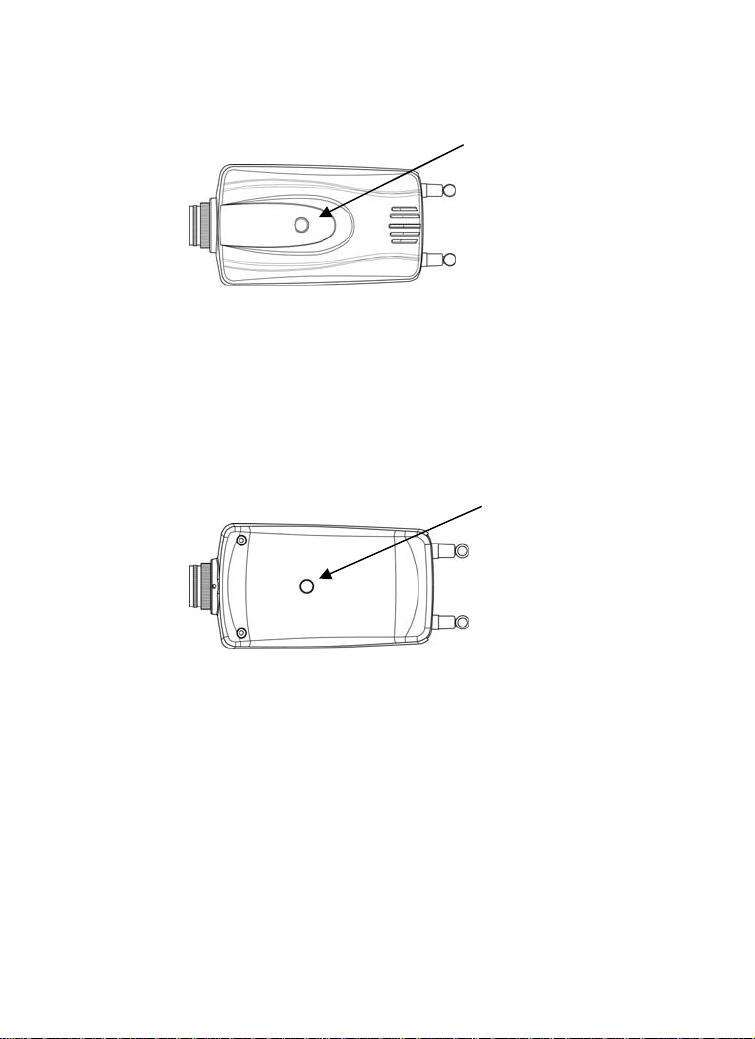
TOP PANEL .......................................................................................... 6
Screw Hole .................................................................................... 6
BOTTOM PANEL .................................................................................. 6
Screw Hole .................................................................................... 6
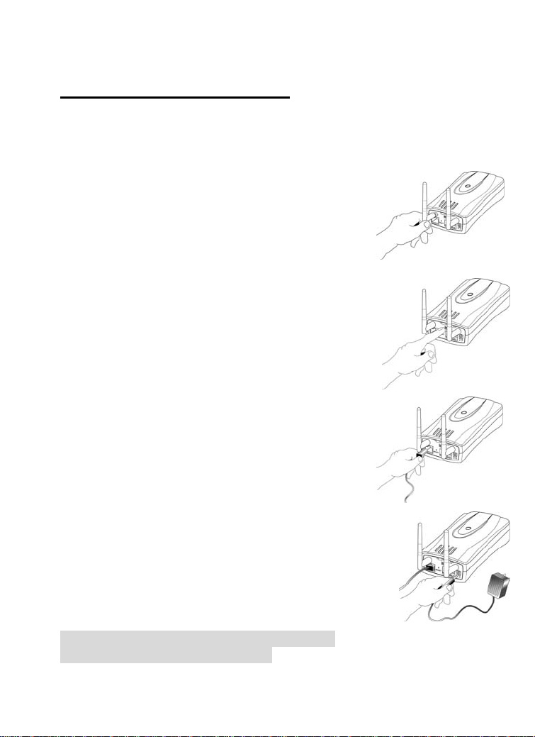
HARDWARE INSTALLATION......................................................... 7
1ATTACH WIRELESS ANTENNA .......................................................... 7
2CONFIGURE NETWORK COMMUNICATION ........................................ 7
3CONNECT AN ETHERNET CABLE ....................................................... 7
4ATTACH THE EXTERNAL POWER SUPPLY........................................... 7
WEB CONFIGURATION.................................................................... 8
INSTALLATION..................................................................................... 8
IPVIEW APPLICATION INSTALLATION ..................................... 9
INSTALLATION..................................................................................... 9
CHANGE IP ADDRESS ........................................................................ 14
APPENDIX.......................................................................................... 17

Introduction
Thank you for the purchase of the Wireless Internet Camera connecting
directly to an Ethernet or Fast Ethernet network and also supported by
the wireless transmission based on the IEEE 802.11b standard. It is
different from the conventional PC Camera, the Wireless Internet
Camera is a standalone system with built-in CPU and web-based
solutions providing a low cost solution that can transmit high quality
video images for monitoring. The Wireless Internet Camera can be
managed remotely, accessed and controlled from any PC/Notebook over
the Intranet or Internet via a web browser. The simple installation
procedures and web-based interface offers easy integration to your
network application environments coupled with many applications such
as remote monitoring for a cost-effective solution.

System Requirement
Wireless Internet Camera
Network:
Local Area Network: 10Base-T Ethernet or 100Base TX Fast Ethernet
Wireless Local Area Network: IEEE 802.11b Wireless LAN
Recommended PC or Notebook to Access the
Wireless Internet Camera
Web Browser:
System requirement:
CPU: Pentium II, 266 MHz or above
Memory Size: 32 MB (64 MB recommended)
VGA card resolution: 800x600 or above
•Internet Explorer 5.0 or above (ActiveX & JAVA Mode –
Image View for Windows OS and JAVA Mode – Image View
for other OS)
•Netscape 6.0 or above (JAVA Mode – Image View)
IPView Application:
Support OS: Win 98, Win 98 SE, Win 2000, Win Me, Win XP
System requirement for IPView:
CPU: Pentium III, 450 MHz or above
Memory Size: 128 MB (256 MB recommended)
VGA card resolution: 800x600 or above

Physical Description
This section describes the features and benefits of the Wireless Internet
Camera
Front Panel
LAN/WLAN LED
Power LED
Power LED
The Power LED is positioned on the right side of the Wireless Internet
Camera’s lens while facing the Wireless Internet Camera.
Steady blue confirms the Wireless Internet Camera is powered on.
Note:
There are three settings for the Power LED to control the light
illumination for monitoring purpose from Normal / Off / Dummy.
Please refer to the Web Configuration section for detailed information
and usage in the User’s Guide.
LAN/WLAN LED
The LAN/WLAN LED is positioned on the right side of the Wireless
Internet Camera’s lens while facing the Wireless Internet Camera. It is
located right of the Power LED
Steady orange confirms good connection to LAN or WLAN
connectivity.
Dependent on the data traffic the LED will begin to flash to indicate that
the Wireless Internet Camera is receiving/transceiving from/to the LAN
or WLAN network.
Note:

There are three settings for the LAN/WLAN LED to control the light
illumination for monitoring purpose from Normal / Off / Dummy.
Please refer to the Web Configuration section for detailed information
and usage in the User’s Guide.
Rear Panel
Slide Switch
12345678
Network Cable
Connector
Reset Button
Antenna Connector Antenna Connector
DC Power
Connector
I/O Connecto
r
Network Cable Connector
The Wireless Internet Camera’s rear panel features an RJ-45 connector
for connections to 10Base-T Ethernet cabling or 100Base-TX Fast
Ethernet cabling (which should be Category 5 twisted-pair cable). The
port supports the NWay protocol, allowing the Wireless Internet Camera
to automatically detect or negotiate the transmission speed of the
network.
DC Power Connector
The DC power input connector is located on the Wireless Internet
Camera’s rear panel and is labeled DC 5V with a single jack socket to
supply power to the Wireless Internet Camera. Power will be generated
when the power supply is connected to a wall outlet.

Reset Button
Reset will be initiated when the reset button is pressed once and Power
LED begins to flash.
Factory Reset will be initiated when the reset button is pressed
continuously for three seconds or when Power LED begins to light up.
Release the reset button and the Power LED will begin to flash
indicating the Wireless Internet Camera is changing to factory reset.
When factory reset is completed the Wireless Internet Camera will be
set to default on channel 11 and EES-ID is set as “NULL String” (This
default setting will let the Wireless Internet Camera connect to ANY
access point on the infrastructure network). The IP address will also
return to the default setting as 192.168.0.20.
Slide Switch
The slide switch permit user’s to determine the type of network
communication media for the Wireless Internet Camera and is
positioned on the rear panel. The three settings are as follows:-
•LAN (Local Area Network)
•LAN/WLAN (Local Area Network/Wireless Local Area
Network)
•WLAN (Wireless Local Area Network)
I/O Connector
There are four I/O connectors, two for input and two for output situated
on the rear panel. The I/O connectors provide the physical interface to
send and receive digital signals to a variety of external alarm devices.
Please refer to the User’s Guide appendix for detailed information.
Antenna Connector
There are two SMA type antenna connectors located at the rear panel of
the Wireless Internet Camera providing connection for two high
sensitivity antenna included with the device.

Top Panel Screw Hole
Screw Hole
Located on the top panel of the Wireless Internet Camera the screw hole
is used to connect the camera stand onto the Wireless Internet Camera
by attaching the screw head on the camera stand into the screw hole of
the Wireless Internet Camera.
Bottom Panel Screw Hole
Screw Hole
Located on the bottom panel of the Wireless Internet Camera the screw
hole is used to connect the camera stand onto the Wireless Internet
Camera by attaching the screw head on the camera stand into the screw
hole of the Wireless Internet Camera.

Hardware Installation
This section describes the Hardware installation procedure for the
Wireless Internet Camera.
1 Attach Wireless Antenna
From the rear panel of the Wireless Internet Camera
screw the 2 external Antenna that came with the
Wireless Internet Camera into the antenna connector..
2 Configure Network Communication
From the rear panel of the Wireless Internet Camera
select the desired Network communication for the
Wireless Internet Camera from the Slide Switch.
Position the Slide Switch to the setting required
either LAN or LAN/WLAN position.
Please refer to the Physical Description
section for detailed information.
3 Connect an Ethernet cable
Connect an Ethernet cable to the network cable
connector located on the Wireless Internet Camera’s
rear panel and attach it to the network.
4 Attach the external power supply
Attach the external power supply to the DC power input
connector located on Wireless Internet Camera’s rear panel
and is labeled DC 5V and connect it to your local power
supply.
Note:
Confirm power source is supplied from the LED
indicators label Power is illuminated.

Web Configuration
Installation
This section describes the Software installation procedure of the
Wireless Internet Camera for Web Configuration and IPView
application.
The Wireless Internet Camera must be configured through its built-in
Web-based Configuration.
Extensive knowledge of LAN will be helpful in setting up the Wireless
Internet Camera
From the web browser enter the default IP address to access the
Welcome screen of the Wireless Internet Camera to configure your
Wireless Internet Camera type http ://192.168.0.20 in the address box.
The number is the default IP address of your Wireless Internet Camera.
Press Enter.
Note:
The PC’s IP address must correspond with the Wireless Internet
Camera’s IP address in the same segment for the two devices to
communicate.
The Welcome screen will appear with a still image as illustrated
below. Select “System Administration” to configure the Wireless
Internet Camera.

IPView Application Installation
Installation
Insert the CD-ROM into the CD-ROM drive to initiated the auto-run
program. Once completed a menu screen will appear as follows:
To install the IPView application click on the "IPView" button to
activate the installation procedure for the application program.
Once executed a prompt will appear requesting the input of the desired
language selection. Make the desired selection and click on “OK” to
continue.

The Welcome screen will appear. Click on the “Next” button to
proceed with the installation.
The License Agreement prompt will appear as below. Read the details
carefully and click on the “Yes” icon to continue with the installation
procedure.

A prompt will appear and in the Destination Location dialog box, you
may click on “Next” to accept the recommended destination location or
click on “Browse” to select another location. After specifying the
desired destination location, click on “Next” to proceed further.
The Select Program Folder prompt will appear providing information of
where the IPView application will be located, click on “Next” to
continue. If you wish to modify your settings, click on “Back” to return
to the previous screens.

Please wait until one of the two dialog box to appear, select either “Yes,
I want to restart my computer now” and click on the “Finish” icon to
restart the computer to complete the installation procedure.
or click on the “Finish” icon to complete the installation procedure

After successfully installing the IPView, the application program
for the Wireless Internet Camera is automatically installed to
\Programs\Files Directory.
To start running the IPView click on windows Start
Menu/Programs/IPView/IPView
Once IPView is executed a Login prompt will appear, you must enter
the default User Name: admin into the respective field and click on
“OK” to log into the application.
Once login, the IPView application is executed and the IPView interface
will appear as follows in the default List View format:

Change IP Address
To change an IP Address for a camera select “Camera” > “Add”. An
Add Camera dialog box will appear as illustrated below.

Click on the “Browse” icon, the Browse Camera dialog box will
appear with a blank screen as illustrated below.
Click on the “Search” icon and IPView will detect and search all the
available camera’s that are installed on the local area network as
depicted below:

You must highlight the camera you wish to change the IP Address and
click on the “Change IP” icon and the Change IP Address dialog box
will appear as depicted below:
Enter the new IP Address along with the Subnet Mask and Default
gateway into the respective fields and click on the “OK” icon and
IPView will automatically change the IP Address.
Make sure to save any changes you have made to keep the information
updated.
Please refer to the User’s Guide for detailed information regarding
IPView application.

Appendix
A
Specification
Video specification
Resolution: 640 x 480 pixel
Sensor: 1/3” color CMOS sensor
Gain control: Automatic
Exposure: Automatic
White Balance: Automatic
Shutter: Electronics 1/60 ~ 1/15000 sec
Focal Length: 6.0 mm
Aperture: F=1.8
Focus Extent: 20 cm - ∞
Lens mounting: Fixed board lens, CS-mount type
Image (Video Setting)
Image compression: JPEG
Frame rate: 20fps@SIF, 6fps@VGA
Compression Rate selection: Auto
Frame rate setting: 1, 5, 7, 15, 20, auto (depends on the
video format)
Video resolution: 320x240, 640x480
Brightness control: Range 1- 128
Contrast control : Range 1- 128
Saturation Yes
Hardware Interface
LAN Connector: One RJ-45 port to connect to 10/100Mbps
Ethernet, auto-sensed
Wireless LAN: Built-in 802.11b wireless LAN module
(Wi-Fi compliant)
Table of contents
Other Repotec IP Camera manuals