Resolution CD55 User manual

1
CD55 CD Player
Owner’s Manual

2
Warranty Registration
•You must be able to show evidence of purchase date to
obtain warranty parts and service.
•Warranty registration of your unit ensures that you will
be contacted immediately if there should be a safety
inspection, modification, or other product recall under
applicable laws or regulations or otherwise.
Model: CD55 CD Player
Serial Number: ___________________
Purchase Date: ___________________
Purchased From: ___________________
SAVEYOUR SALES SLIP AND MAILWARRANTY REGISTRATIONTO RESOLUTION AUDIO
Safety Precautions
The lightning flash with an arrowhead sym-
bol,within anequilateraltriangle,isintended
to alert the user of the presence of
uninsulated “dangerous voltage” within the
product’s enclosure, thatmaybeof sufficient
magnitude to constitute a risk of electric
shock to persons.
The exclamation point within an equilateral
triangle is intended to alert the user of the
presence of important operating and main-
tenance (servicing) instructions in the litera-
ture accompanying the product.
•Check that the operating voltage of your unit is identi-
cal with the voltage of your local power supply.
•Replace fuses only with identically rated fuses.
•To reduce risk of electric shock keep unit dry and
grounded. Do not operate the unit near water.
•If the unit causes RF interference with another product,
move one unit or both until the interference is elimi-
nated. If interference cannot be sufficiently reduced,
cease operation and consult your dealer.
•Clean the chassis, faceplate, and controls with a soft
cloth lightly moistened with mild detergent solution. Do
not use any type of abrasive pad, scouring powder or
solvent such as alcohol or benzine.
•Do not discard the original box and packing material.
When shipping the unit to another location or for repair
work, repack in original material and double box the
contents.
•Do not attempt to service this product. All servicing
should be referred to qualified service personnel.
•Do not install the unit in a location near heat sources
such as radiators or heat ducts, or in a place subject to
mechanical vibration or shock.
Warranty
Resolution Audio warrants all products against faulty workmanship or defective materials for a period of three (3) years from
date of shipment, with the exception of transport mechanisms. Transport mechanisms are covered for one (1) year. If a
defect occurs within this period, Resolution Audio will repair, replace or issue credit for the unit at our discretion. Prior return
authorization is required.All merchandise must be returned in the original packing material and double boxed.If a product is
recalled and the product is not returned within 60 days, the warranty is void.This warranty is not transferable. Resolution
Audio assumes no responsibility for defects resulting from misuse, neglect, improper installation, unauthorized repair, alter-
ation, inadequate packing, or accident. No other obligations expressed or implied shall be assumed by Resolution Audio.
RISK OF ELECTRIC SHOCK
DO NOT OPEN
CAUTION
CAUTION: TO REDUCE THE RISK OF ELECTRIC SHOCK
DO NOT REMOVE COVER
NO USER-SERVICEABLE PARTS INSIDE
REFER SERVICING TO QUALIFIED SERVICE PERSONNEL

3
CD55 CD Player
Thank you for purchasing the CD55 CD Player.When Resolution began design of the CD55, we sought to offer
true high-end performance in a single-box player.Accordingly, the CD55 utilizes quality components throughout
the unit.For the CD drive mechanism we selected the Philips P10500, their latest high-end offering.This mecha-
nism has greater reading capability than their previous designs and can also read unfinalized CD-RWs. Digital
filtering is implementedthroughacustomprogrammableDSP.Our filter isalsoHDCDcompatible.Thedigital-to-
analog conversion is accomplished by four Burr-Brown 1704 (96/24) DACs in a balanced configuration.The DAC
outputisthenfedtoanultra-lownoiseanalogoutputstagewithanalog volumecontrol.Every aspect of the player
was designed for maximum performance. We are very pleased with the CD55 and hope that you will enjoy
listening to it as much as we do.
Front Panel and Controls
1) Main Display – Indicates track and time informa-
tion. Also shows status for Repeat, Program, and
Shufflefunctions.
2) Invert – Indicates normal phase (0 degrees) when
dark and inverted phase (180 degrees) when lit.
3) Volume Display – Indicates volume level from 0
(mute) to 99 (full scale).
4) Volume Controls – These buttons are used to in-
crease or decrease volume level.
5) HDCD– Indicates HDCDdecoding when lit.
6) Track Forward – This button advances one track
witheach press.Holdingthisbuttonadvancestracks
rapidly.
7) Track Backward – This button successively backs
up one track with each press. Holding this button
will rapidly back through tracks.
8) Stop –This button stops play.
9) Pause –This button pauses play at current point in
track.To resume, push Pause again.
10) Play – This button commences playback.
11) Open / Close – This button activates the drawer.
Do not push the drawer to close it.
HDCDis a registered trademark of Pacific Microsonics, Inc.
456
7
8
9
1011
2 31

4
Rear Panel and Connections
1) DINConnector–Analog output connector forcon-
nection to European products.
2) Single-Ended Analog Outputs – RCA connector.
3) Balanced Analog Outputs – XLR connector.
4) PowerEntry –IECpower connector, doublefused.
Standby
Vol –
Store 1
Phase
Repeat 456
Time
Shuffle
Vol +
23
789
0
resolution
Remote Control
Keypad–Thesekeys, 0-9,canbeused to enter atrack
number directly.For example, to play track three press
the three key and then press PLAY.To play track ten,
press the one key, then the zero key, then press PLAY.
Standby–TheSTANDBYbutton instructs the CD55 to
toggle between power-up and standby.When the unit
isinstandby,the displaywill be turnedoff.Volumecon-
trol settings will be retained.
Phase – Pressing this button will toggle between nor-
mal phase (0 degrees) and inverted phase (180 de-
grees).
Store –This button can be used to store tracks for pro-
grammed playback.To program tracks, enter the track
number, followedbySTORE.Repeatforeachtrackpro-
grammed.When complete, press PLAY to begin play-
back.
Repeat – Pressing this button will toggle the player
throughthreestates:NoRepeat (normalplay),Repeat-
1 (same song), and Repeat All (entire disc).
Time – Pressing this button will toggle the display
through three display modes: time elapsed into track
(normalplay),time elapsed into disc,andtimeremain-
ing on disc.
Shuffle – Pressing this button will invoke random play
until all selections have been played.
23 43
2
1

5
Basic Operation
Setup requires three steps:
1) Plug power cord into IEC inlet.
2) Connectanalogoutputstopreamplifier or amplifier.
3) Activate power switch on rear panel.
The eight front panel switches can control basic func-
tions. Other features can be accessed using the re-
mote control.
Open / Close
Press OPEN / CLOSE to insert or remove a disc. Al-
though this button can be pressed during normal play,
we recommend pressing STOP prior to activating the
drawer. Do not push tray to close it.
Play
Once a disc has been inserted, press PLAY to com-
mence playback.If PLAY is pressed in the middle of a
track, playback will commence from the beginning of
the same track.
Pause
Press PAUSE during play to stop at a particular point.
To resume play, press PAUSE again.If PLAY is
pressed, playback will resume at the beginning of the
track.
Stopping play
Press STOP to cease playback.
Skipping ahead or back
Press TRACK FORWARD to skip ahead by one track
each time the button is pressed.
Press TRACK BACKWARD to skip back by one track
eachtimethe buttonis pressed.If the buttonis pressed
once midway through a track, play returns to the start
of the previous track.
Rapid advance (Rapid reverse)
This function can be invoked through the remote con-
trol. Press SEARCH FORWARD or SEARCH BACK-
WARD to moveforward orbackwardwithinatrack.The
speedofthe advance(reverse)isrelatively slowatfirst,
then becomes faster.
Volume Control
Use these buttons to raise and lower volume level.
The range has a low of 0 (Mute) to a high of 99 (full
scale).
Notes:
•The first time the power switch is activated on the
backpanel, the unit willpowerup at avolumelevel
of 50.
•If unit is connected to a preamplifier, set the vol-
ume level at 99.
•At level 0 (Mute), volume display will turn off.
Specifications
CD Mechanism: Philips P10500
Master Clock Jitter: Below measurable levels
Digital Filter: 16x hybrid design incorporating custom Resolution software DSP
and Pacific Microsonics PMD-100 with HDCDdecoding.
Digital/AnalogConverters: Four (4) Burr-Brown PCM1704 24-bit DACs
Current-to-Voltage: Passive
Analog Filter: 3rd Order Passive
AnalogAttenuation: 0.5 dB steps from -30 dB to full scale
1.0 dB steps from -69 dB to -31 dB
Analog Outputs: Balanced XLR, Single-ended RCA, DIN
OutputVoltage: 3.5 V RMS
OutputImpedance: 100 Ohms
PowerRequirements: Preconfigured at factory
100-120/200-240VAC, 50/60 Hz
Power Consumption: 35 Watts
Weight: 25 lbs. / 11.5 kg.
Dimensions: 17.00 W x 12.50 L x 3.50 H (inches)
430 W x 320 L x 90 H (mm)

6
CD55 Design Features
1) Custom CD Servo PCB – Resolution designs its
own circuit boards to control the CD mechanism.
By taking control of servo board design, we can
insure that the clock circuitry and signal paths are
optimized for low noise and jitter. In addition, we
are able to keep the interface with the main circuit
board consistent, so that if a new mechanism is
required later for servicing, compatibility will not
be an issue.
2) PhilipsP10500Mechanism –Thisisthelatesthigh-
end drive mechanism offered by Philips. The
P10500 offers improved disc reading capability
compared to their previous designs. It can even
read unfinalized CD-RWs. The P10500 is driven
by a Hall effect motor and will deliver a long life-
time of reliability.
3) Hybrid Digital Filter Architecture – The CD stan-
dard calls for music to be sampled 44,100 times
each second. Each of these samples is assigned
a value from 0-65,535. This value represents a
voltage that is used to reproduce the musical sig-
nal.Thepurpose of an oversampling digital filter is
tocalculateintermediatedatapoints betweeneach
sample.Useofthistechniquegreatly improves the
sonic performance of the CD playback system.
Every multi-bit CD player uses digital filter tech-
nology.Typically,8x oversamplingis used.Inother
words, every second 44,100 samples enter the fil-
terandget transformedinto352,800 separatedata
points.Thetwo primaryapproachesforimplement-
ingdigital filtersisthroughdedicatedsilicon, orsoft-
ware programmable digital signal processors
(DSPs).We have pursued a hybrid approach that
exploits the best characteristics of both methods.
By using both a Motorola DSP incorporating our
own custom code and the Pacific Microsonics
PMD-100,weareabletoachieve16xoversampling
whilepreservingtheHDCDdecodingprocess.Be-
causetheDSPis reprogrammable,wecan update
thecodeatalatertimeifbetterfiltering algorithms
are developed.
1
2
7
8
3
4
5
6

7
4) Low Jitter Master Clock – The CD55 electronics
are synchronized by a low jitter master clock. In
Resolution CD players, the clock is located close
to the D/A converters to keep timing as accurate
as possible. By contrast, many common designs
locate the master clock at the CD mechanism.
These designs must pipe the clock to the convert-
ers, sometimes over very long lines, and typically
exhibit a great deal of jitter at the D/A converters.
5) Balanced D/A Conversion – The CD55 uses two
D/A converters per channel to achieve balanced
conversion.The primary benefit of balanced con-
version is that it eliminates noise introduced in the
conversionprocess,aphenomenonknownascom-
mon mode rejection. In short, both the right and
left channels are split into plus and minus signals
(180degreesout of phase)prior toconversion and
decoded by separate converters. As a result, any
noise introduced disappears when the plus and
minus phases are later combined.
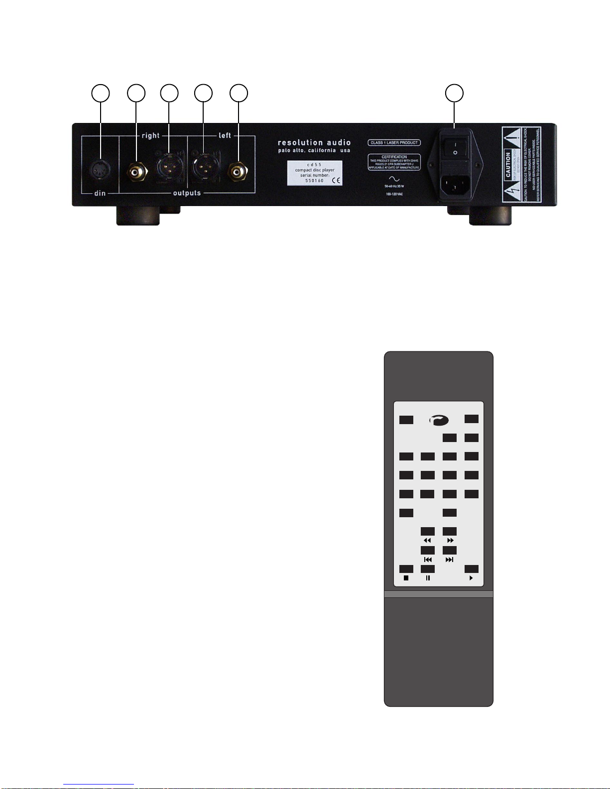
To enjoy the benefits of balanced conversion, bal-
anced connectors (XLR) are used to connect to
the preamplifier.Most units with balanced conver-
sion also offer single-ended outputs (RCA). Many
manufacturers will simply discard the minus out-
put of balanced conversion and connect the posi-
tive output to the single ended connector. While
this approach is inexpensive, it usually results in a
sonicdifferencebetweenthesingle-ended andbal-
ancedconnectors.Toreduce this difference,Reso-
lutionsumsthe plus andminussignalsbeforecon-
necting to the single-ended connectors. As a re-
sult,oursingle-ended output performsatthesame
high level as our balanced outputs. Any sonic dif-
ference noted between the outputs is often due to
the cables or the preamplifier interface.
6) Low Noise Analog Output w/AnalogVolume Con-
trol–Thehigh resolution of the24-bitD/Aconvert-
ers requires an equally detailed analog output
stage.To keepunnecessarycircuitry toaminimum,
we chose to use passive current-to-voltage (I/V)
conversion. Passive I/V maintains linearity and a
constantimpedance throughthecircuitwhileavoid-
ing problems inherent in active stage designs.
The analog output contains a volume attenuator
that provides precision volume control with mini-
mal signal degradation. In contrast to digital-do-
mainvolumecontrol, noconverterresolutionislost.
In addition, the 6 dB boost required for some
HDCDsources is automatically detected and ac-
tivated using the analog attenuator.While digital-
domain attenuation reduces effective converter
resolution by 1 bit for non HDCDsources, and
analog-domain approaches require signal switch-
ing, this approach avoids both these limitations.
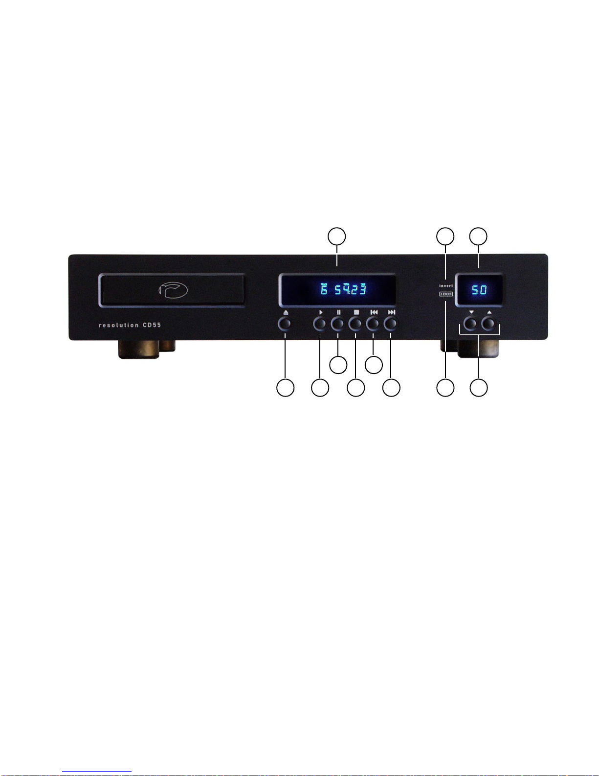
Volume level is indicated on the front panel as a
number between 0 (mute) and 99 (full scale).The
output level is adjustable by 0.5 dB steps from full
scale to -30 dB (40-99).From -31 dB to -69 dB (1-
39) the level is adjustable in 1 dB steps.
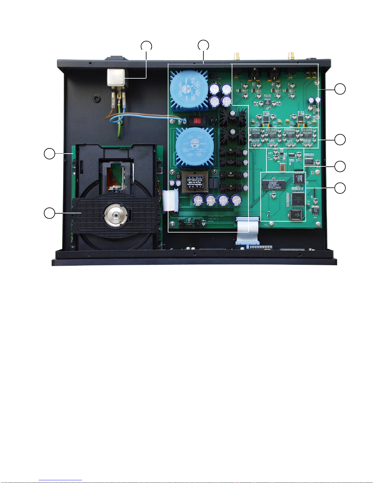
7) Robust Power Supply – Power supply design is
important for two reasons. First, a well designed
supplyshouldnotcontribute anyextraneousnoise
to the system.If power supply noise leaks into the
digitaldecoding oranalogoutput circuitry, thenoise
floor will be much higher and power supply har-
monics will degrade sonic performance.
The power supply must also be able to deliver re-
quired power levels to the circuitry over a wide
rangeof voltages(100-240) and50/60Hz frequen-
cies. An inadequate supply can cause behavior
ranging from poor performance, to system failure.
Consequently, we have dedicated three separate
transformers to guarantee that the supply is both
robust and low-noise. Toroidal transformers are
particularlysuitedforhigh-endaudioapplications.
8) A/C Filtering – The power entry module incorpo-
rates a master power switch, fusing, and A/C line
filtering. The A/C filter serves a dual purpose in
that it cleans the incoming power while also pre-
venting digital noise from escaping the unit. The
power entrymoduleusesa standard IEC interface
to the power cord, allowing the customer to use
the player in multiple countries.
9) Miscellaneous – The CD55 also contains many
otherdesign features.Forexample,wiring hasbeen
kept to a minimum to improve manufacturability,
reliability, and performance.Where wiring is used,
lengths are kept short to prevent noise pickup.
From a structural point of view, the chassis and
top are fabricated from 16-guage steel.Steel pro-
vides a good RF shield that reduces interference.
The chassis bottom includes two additional foot
mountsthatallowthecustomer to arrangethe sup-
ports in a tripod configuration, or add isolation ac-
cessories using standard 1/4-20 threads.
Resolution Audio •(415) 643-6971 •www.resolutionaudio.com •info@resolutionaudio.com
Table of contents
Other Resolution CD Player manuals