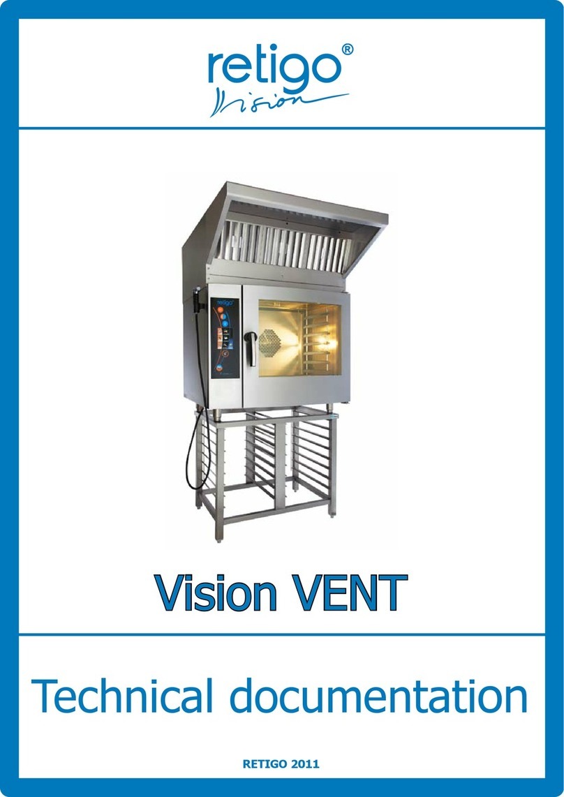
Retigo VISION vent 2 Guide

HOOD
VISION VENT 2
Perfection in cooking and more...
READ THIS MANUAL BEFORE USE
TECHNICAL DOCUMENTATION


3
CONTENTS
BASIC INFORMATION ............................................................................................................................5
PREAMBLE .............................................................................................................................................................................................................................5
1. ABOUT THIS MANUAL ....................................................................................................................................................................................................5
2. USING AND OPERATING THE HOOD.........................................................................................................................................................................6
3. UNINTENDED USE ..........................................................................................................................................................................................................6
4. IMPORTANT INFORMATION.........................................................................................................................................................................................6
5. USING THE OPERATING MANUAL ..............................................................................................................................................................................6
6. KEY REGULATIONS .........................................................................................................................................................................................................6
7. LIMITATION OF LIABILITY ..............................................................................................................................................................................................7
SAFETY INSTRUCTIONS ........................................................................................................................8
1. GENERAL SAFETY INFORMATION................................................................................................................................................................................8
2. DESIGNATING OPERATING PERSONNEL ..................................................................................................................................................................8
3. PERFECT CONDITION....................................................................................................................................................................................................8
4. SAFETY RULES FOR WORKING WITH THE RETIGO APPLIANCE..........................................................................................................................8
TECHNICAL INFORMATION .................................................................................................................9
1. MAIN TECHNICAL CHARACTERISTICS .......................................................................................................................................................................9
2. NAMEPLATES OF 0610, 2011 AND 623 HOODS.....................................................................................................................................................12
TRANSPORT AND INSTALLATION .....................................................................................................13
1. TRANSPORTING THE APPLIANCE..............................................................................................................................................................................13
2. WASTE DISPOSAL..........................................................................................................................................................................................................13
4. ELECTRICAL CONNECTIONS FOR AN 0610 OR 2011 HOOD ............................................................................................................................15
5. ELECTRICAL CONNECTIONS FOR A623 HOOD...................................................................................................................................................18
6. FITTING A0610 HOOD ONTO ACONFIGURATION OF TWO APPLIANCES .................................................................................................. 20
7. HOOD SETTINGS AND CONTROLS ..........................................................................................................................................................................21
8. FAULT REPORT IN CONNECTION WITH THE HOOD...........................................................................................................................................23
MAINTENANCE AND CLEANING................................................................................................................................................................................... 24
Technical documentation I Vision Vent 2 Hood I Contents


5
BASIC INFORMATION
PREAMBLE
RETIGO s.r.o. thanks you for choosing a Retigo product! Your
new appliance brings together years of experience with the best
professional chefs and state-of-the-art science and technology.
To ensure your satisfaction from the very beginning, we would like
to provide you with this manual containing the information and
sensible advice you need for trouble-free use of the appliance.
We hope that you enjoy working with this RETIGO appliance and
that your customers will always be satisfied.
1. ABOUT THIS MANUAL
WHO THE IS MANUAL FOR
This manual is intended for anyone who only comes into contact
with the appliance during its maintenance or operation. All such
persons must study the manual carefully before beginning any kind
of work with the appliance.
IMPERATIVE
Study the manual carefully. It should be seen as a part of the
appliance and it must not be separated from the appliance. So keep
it for future use and in case of resale later.
Follow its instructions exactly, not only to make using the appliance
easier, but also to ensure its optimal use and long life.
Do not start the appliance unless you are familiar with all the
instructions, warnings and recommendations set out here,
especially those in the "Safety Instructions" chapter.
The illustrations in this manual may not always correspond to an
actual appliance. Their purpose is to describe the main features of
the appliance.
The complete technology documentation for the appliance can
be found at the manufacturer'swebsite.
WHEN IN DOUBT
Unforeseeable situations that cannot be included and described in
this manual may often arise in practice. Therefore, when you're not
sure what to do, always contact the manufacturer:
Retigo, s.r.o.
Láň 2310
756 64 Rožnov pod Radhoštěm
Tel./Fax: +420 571 665 511
INFORETIGO.CZ
WWW.RETIGO.CZ
IN case of doubt, don't hesitate to contact our highly trained
specialists:
PROFESSIONAL SALESPEOPLE:
+420 603 571 360
+420 604 568 562
PROFESSIONAL CHEFS:
+420,734,751,061
+420,727,867,220
PROFESSIONAL SERVICE TECHNICIANS:
+420,605,769,916
+420,733,641,315
When contacting the manufacturer or trained specialists, please
have your hood’sbasic information ready to hand.
This can be read from the nameplate located on the right side.
This shows the appliance’smanufacturer, technical data, such as
type and model, serial number, production year, and important
information on the type of power supply, weight and protection
against water.
Technical documentation I Vision Vent 2 Hood I Basic information

6
2. USING AND OPERATING THE HOOD
Retigo hoods are intended for the extraction and condensation
of waste steam from RETIGO appliances and are designed for the
Vision range of models, in production since May 2017. They are
controlled electronically from the relevant appliance. The hoods
are intended only for RETIGO electric appliances and cannot be
installed on gas appliances.
After the door of the appliance is closed and cooking begins,
the temperature inside the cooking chamber of the appliance
is monitored. If the temperature exceeds the level at which the
hood is activated, extraction starts at aslow rate. If the door of the
appliance is opened during cooking or after cooking is completed,
the hood temporarily switches to afaster rate in order to extract any
steam more eectively. After the door is closed, the hood reverts to
aslow rate. Extraction stops when the temperature of the cooking
chamber dips below the activation level or if the appliance door is
left open for some time.
The manufacturer has issued an EC declaration for the hood
3. UNINTENDED USE
Any other possible uses shall be regarded as unintended use.
RETIGO s.r.o. shall not be liable for the resulting damage. In such
cases the risk shall be borne by the user!
4. IMPORTANT INFORMATION
• This appliance is not intended for use by people (including
children) with physical or mental disabilities or who lack the
experience or knowledge to use the appliance safely, unless they
are supervised or instructed to use the appliance by a person
responsible for their safety. Make sure that children do not handle
the appliance.
• Careful study of the operating manual will provide you with
important information on the design, control and safe operation
of the appliance.
• After unpacking the appliance, make sure that the delivery is
complete.
CONTENTS OF HOOD DELIVERY PACKAGE:
Type 0610: hood, 3 grease filters, sheet metal cover (for installing
the hood onto an appliance with a left door), 0610 hood set,
technical documents
Type 2011: hood, 3 grease filters, sheet metal cover (for installing
the hood onto an appliance with a left door), UTP cable, UTP
splitter, 2011 hood set, technical documents
Type 623: hood, 3 grease filters, sheet metal cover (for installing the
hood onto an appliance with aleft door), 623 hood set, technical
documents
• Check to see if the appliance is the right type for the required use.
• Installation should be carried out only by a properly certified
professional.
• The appliance must be connected in accordance with the
applicable regulations and standards and the operating manual.
• Adjustment and first start-up should be done only by aservice
mechanic with a valid certificate from the manufacturer.
A list of our contracted service companies can be found at:
www.retigo.cz.
• Faulty connection may cause damage, for which the manufacturer
shall not be liable.
• Maintain and clean only according to the prescribed instructions.
• If the appliance malfunctions, contact your dealer or service
partner, or one of the service companies listed at: www.retigo.cz.
UNAUTHORIZED TAMPERING MAY DAMAGE THE DEVICE!
• For proper functioning, safety and long-term operation, we
recommend regular annual inspection and maintenance by
one of our contracted service companies. This will protect your
investment.
• When finishing work with the appliance, switch o the electricity.
• Use only original parts for repairs.
• The manufacturer accepts no responsibility for defects caused
by improper installation, or by failure to comply with regulations,
standards or the operating manual during installation or
operation, and the warranty does not apply to such defects.
• The appliance is intended only for professional use and must be
operated by trained, qualified personnel.
5. USING THE OPERATING MANUAL
Read the operating manual thoroughly. Follow the operating
manual during work, cleaning and maintenance. If you are not
sure how to perform a certain task, ask your salesperson or the
manufacturer.
5.1 SYMBOLS USED
The symbols used in this manual draw attention to activities that
may aect safety, health or the need for inspection, helping you to
avoid problems.
SYMBOLS USED IN THE DOCUMENTATION
In this documentation you will find symbols with the following
meaning:
SYMBOL MEANING
These symbols mean
"ATTENTION" and
"WARNING", they inform you
about things that may cause
serious injury to the user and/
or damage to the machine.
Furthermore, they indicate an
important instruction, feature,
method or issue that must be
followed or considered when
operating or maintaining the
appliance.
This symbol indicates useful
information related to the
appliance or its accessories.
This symbol is a reference
to another chapter in the
manual.
It indicates other procedure
options that you may, but do
not necessarily have to, apply.
6. KEY REGULATIONS
The generally applicable legislation and other binding rules for
accident prevention and environmental protection are not listed
individually, but must be followed as strictly as possible. Examples
of these regulations include:
• ČSN EN 60335-1 ed.2:03
+A11:04+A1:05+A12:06+A2:07+A13:09+A14:10+ A15:12
• ČSN EN 60335-2-99:04
Technical documentation I Vision Vent 2 Hood I Basic information

7
• ČSN EN 61000-6-2 ed.3:06
• ČSN EN 61000-6-4 ed.2:07+A1:11
• Act No 22/1997, Government Regulation NV 17/2003 and
616/2006.
• Directives of the European Council: 2006/95/EC and 2004/
108/EC.
The manufacturer has issued an EC declaration for the hood.
7. LIMITATION OF LIABILITY
All technical information, data and operating and maintenance
instructions contained in the operating manual reflect the situation
current at the time of delivery and are based on our experience
to date and our best knowledge. In the context of continuing
development, we reserve the right to introduce technical changes
to appliances covered by this operating manual. We accept no
liability for damage or breakdowns caused by wrong operation,
failure to comply with this operating manual, use of aggressive
chemical cleaning agents or incorrect repairs. Note especially that
this also applies to replacement parts that we have not delivered
and to accessories that we have not tested or approved.
For safety reasons, Retigo shall approve no reconstruction or
modification to the appliance carried out by the user, and shall
accept no liability for damage caused in this way. The company
shall be liable for unintentional errors or omissions falling within
its warranty responsibilities as agreed in the contract and to the
exclusion of other claims.
No claims may be made for compensation for damages irrespective
of the legal grounds.
Technical documentation I Vision Vent 2 Hood I Basic information

8
SAFETY INSTRUCTIONS
1. GENERAL SAFETY INFORMATION
This documentation contains the information required for suitable
use of the product described. Knowledge and application of
the safety instructions and warnings in this documentation are
a prerequisite for the safe start-up, operation and maintenance
of the appliance. For purposes of clarity, the documentation does
not contain all details of all versions of the described product, and
they cannot cover every conceivable case to be considered during
operation and maintenance. If you need further information or have
problems that are not adequately described in our documentation,
please contact your sales representative or the manufacturer by
telephone or in writing.
2. DESIGNATING OPERATING PERSONNEL
Decide who will work with the appliance, and train the person.
The appliance is intended only for professional use and must be
operated by trained, qualified personnel.
3. PERFECT CONDITION
Operate the appliance only in perfect condition. Do not remove any
safety equipment such as covers etc. Do not modify the appliance
in any way.
4. SAFETY RULES FOR WORKING WITH
THE RETIGO APPLIANCE
To work safely with the appliance, remember the following safety
rules. This will avoid arisk to your health!
Do not use aggressive and highly alkaline cleaning agents.
Damage resulting from incorrect cleaning are not covered by the
warranty. Carefully read the safety instructions on the product
labels of the cleaning agents. Do not use pressure cleaners or water
sprays to clean the cooking chamber or the outer surfaces of your
appliance.
Technical documentation I Vision Vent 2 Hood I Safety instructions

9
Technical documentation I Vision Vent 2 Hood I Technical information
TECHNICAL INFORMATION
1. MAIN TECHNICAL CHARACTERISTICS
0610 hood
Weight: 60 kg
Dimensions (height, width, depth): 1126 x 939 x 409 mm
Noise level – min/max: 63 dB/ 68 dB
Maximum air flow: 1000 m3/hour
Maximum power consumption: 400 W
Voltage: 1N~(2~)/200-240V/50-60Hz

10
2011 hood
Weight: 60 kg
Dimensions (height, width, depth): 1133 x 953 x 410 mm
Noise level – min/max: 63 dB/ 68 dB
Maximum air flow: 1000 m3/hour
Maximum power consumption: 400 W
Voltage: 1N~ (2~)/200-240V/50-60Hz
Technical documentation I Vision Vent 2 Hood I Technical information

11
623 hood
Weight: 40 kg
Dimensions (height, width, depth): 633 x 689 x 259 mm
Noise level – min/max: 46 dB/ 50 dB
Maximum air flow: 760 m3/hour
Maximum power consumption: 165 W
Voltage: 1N~ (2~)/200-240V/50-60Hz
Technical documentation I Vision Vent 2 Hood I Technical information

12
2. NAMEPLATES OF 0610, 2011 AND 623
HOODS
The nameplate is located on the left side of the hood, at the
bottom. The nameplate states the manufacturer of the appliance,
technical information and marks indicating that the product fulfils
the applicable standards.
Technical documentation I Vision Vent 2 Hood I Technical information

13
Technical documentation I Vision Vent 2 Hood I Transport and installation
TRANSPORT AND
INSTALLATION
1. TRANSPORTING THE APPLIANCE
1. 1 Instructions for transporting the
appliance
Take all possible care when transporting the appliance. Take
particular care during transport to ensure that the appliance is not
damaged.
WHEN RECEIVING THE PRODUCT:
• immediately check the number of items against the accompanying
• documents (delivery note, invoice, freight note)
• inspect the condition of the packaging and equipment.
IF THERE IS ANY DAMAGE, DO THE FOLLOWING:
• request a“damage report“ on the spot
• take detailed photos of the damage.
• if the damage appears to be greater than CZK 10,000, we
recommend consulting an insurance assessor
• Have the damage report confirmed by the driver, transport
company or airport employee.
The packaging will not protect the appliance from impact or
pressure from sharp or blunt objects.
After unpacking the appliance, check to see that the delivery
is complete according to the delivery slip, and remove all
documents and packing material from inside the appliance.
2. WASTE DISPOSAL
Under Act 477/2001 (94/62/EC), Retigo s.r.o. is authorized to use
the Green Dot symbol, which means that the price of the product
includes costs associated with disposing of the packing material.
According to Section10 of Act 185/2001 Coll. on refuse, follow the
instructions below:
2. 1 Disposing of packaging
Take the cardboard for recycling. Place the protective film and
polystyrene supports into a recycling collection container for
plastics.
2. 2. Disposing of the appliance after the end
of its useful life
The appliance can then be taken out for recycling.
3. INSTALLING THE APPLIANCE
Operate the appliance only in perfect condition. Do not remove any
safety equipment such as covers etc. Do not modify the appliance
in any way.
3. 1 Preparing the appliance for installation
• Before installing the hood, disconnect the appliance from the
power supply.
• Always install the hood in accordance with the regulations and
standards applicable in your country.
• The hood will only work correctly if installed on an appliance with
the following software versions:
Blue Vision – version 2.28 or higher
Orange Vision – version 3.49 or higher
• Unpack the hood carefully from the transport packaging and
remove the protective cover.
• The hood is made for operation on an appliance with a right
opening door. If it is installed on an appliance with aleft opening
door, the hood’sfront cover should be replaced. The cover forms
part of the delivery.
• The hood must be modified if it is to be mounted onto
acombination of two appliances. To modify the hood, follow the
"Set for combination with hood", Article AA11-9908.
3. 2 Fitting the hood onto the appliance
• Remove the side cover of the appliance onto which the hood is
to be installed. Unscrew the bolts of the cover using ascrewdriver
and aNo. 8 spanner, see fig. 1.
Figure 1: 0610 hood for appliance size 611

14
Technical documentation I Vision Vent 2 Hood I Transport and installation
• Fit the 0610 hood onto the appliance, taking care to correctly
connect the hood input (the tube at the back of the hood) onto
the appliance’sflue - see fig. 2. Due to the weight of the hood,
asucient number of persons will be needed for this operation.
Figure 2: Fitting the tube into the flue for an 0611 hood
• Fitting a623 hood to an appliance
Figure 3: Fitting a623 hood
• Fit the grease filters supplied with the hood to the suction
opening in the front part of the hood.
• Start with the two outer filters (they have arim) (see fig. 4), and
then insert the middle filter between them.
Figure 4: Grease filters in a0610 hood
• The procedure for installing filters to a623 hood is the same as
the one described above (see fig. 5)
Figure 5: Grease filters in a623 hood
3. 3 Checking the installation point
Check to make sure the electrical connection parameters match
the parameters on the nameplate. This will help you avoid problems
and delays in installing.

15
4. ELECTRICAL CONNECTIONS FOR AN
0610 OR 2011 HOOD
The hood may be connected only to anormalized voltage network,
whose parameters match the data listed on the hood’snameplate.
The hood must be protected by afuse of up to 16A.
At the back of the hood there is an M6 bolt (6), which is for the
protective couplings, see fig. 6. Connect it to asuitable cable and
make the protective couplings
4. 1. Connecting the control parts
At the back of the hood, there is a plastic distributor (4), from
which the controlling UTP cable (2) emerges, at the end of which is
connector RJ-45 (see fig. 6).
Cut across-shaped opening in the rubber grommet (1) on the edge
of the hood. Pass the UTP cable (2) through the opening and run it
to the pierced flanges (3) at the back left corner of the base of the
appliance (see fig. 6)
Figure 6: Back of 0610 hood
In the base of the appliance, break through the flange marked with
the number “2” (see fig. 7a or 7b), insert aM20x1.5 cable gland into
it, thread the UTP cable through it from the bottom of the appliance
upwards and fasten it securely.
Figure 7a: Location of the flanges on the base of an appliance of
size 611
Figure 7b: Location of the flanges on the base of an appliance of
size 2011
On the appliance'selectrical board, next to the relay panel, there is
arubber grommet (1). Thread the UP cable through this grommet
(2) and guide it towards the front of the electrical board (see fig. 8)
Figure 8: Threading the UTP cable through the rubber grommet
Fit the end of the UTP cable (2) into RJ-45 port (1), marked X4 or X5
on the relay panel (3) (see. fig. 9).
Technical documentation I Vision Vent 2 Hood I Transport and installation

16
Figure 9: Fitting the UTP cable into the RJ-45 port
If both ports are already in use (only in the case of appliance size
2011, model Blue), use an RJ-45 splitter (1) and the attached short
UTP cable (2), see fig. 10. Connect the original UTP cable (3) to the
port as well.
Figure 10: Connecting the RJ-45 splitter
4. 2 Connecting the control parts
At the back of the hood (see fig. 6), there is aplastic distributor (4),
from which the 3 x 1.5mm2power cable emerges(5), terminating in
loose leads. Thread this cable through the rubber grommet in the
same way as the UTP control cable.
The hood may be powered either from a separate electrical
connection (fixed or movable) or directly from the appliance. The
method of connecting the power part depends on which of these
options is selected. Connecting the control part is the same in both
cases.
POWERING FROM AFIXED ELECTRICAL CONNECTION
Attach the free end of the cable to the fixed electrical supply, which
must contain amulti-pole breaker device (switch) with aminimum
distance of 3mm between the contacts.
POWERING FROM AN ELECTRIC PLUG
On the free end of the cable attach a suitable power plug (not
included in the package) for the country of use. The plug must be
inserted into asocket that is within easy reach.
POWERING FROM THE APPLIANCE
The hood can be attached in this way only to an appliance powered
from the following mains supply:
• 3N~/380-415V
• 3~/200-240V
• 1N~(2~)/220-240V
Using any another power source can destroy the hood!
Make sure that the appliance is disconnected from the power
supply.
Remove the left side cover of the appliance.
Loosen the control panel by unscrewing the M4 bolt with washer
(1) from underneath the control panel (see fig. 11), and remove the
panel by sliding upwards, pull out towards you and flip out to the
left.
Figure 11: Loosening the control panel
Disassemble the relay panel from the plastic spacers. Using flat-
nose pliers, loosen the polyamide spacers (1, 2, 3, 4) on which the
power board is axed (see fig. 12). Carefully lift the relay panel and
cables away from the aluminium panel to create room for work
between the electrical board and the back of the power board.
Technical documentation I Vision Vent 2 Hood I Transport and installation

17
Figure 12: Positioning the plastic spacers
Screw the DIN rail with fuse and terminals from the hood set (1)
onto the back of the electrical board in the prepared openings using
M4x10 bolts and the cushioning pads and nuts (part of the set) (see
fig. 13).
Longer bolts should not be used, under any circumstances!
Put the relay board back onto the plastic spacers, applying light
pressure to secure it.
Figure 13: Connecting the 0610 hood set
Depending on the type of electrical connection used for the
appliance, insert either the X39A (3N~/380-415V) or the X39B
(3~/200-240V) connector from the hood set into plug X39, which
leads from the main terminal block.
The hood could be destroyed by connecting the wrong
connector to plug X39!
In the base of the appliance, break through the flange marked with
the number “3” (see fig. 7a or fig. 7b), insert cable gland PG 13,5
(which is acomponent of the hood) into the gland and thread the
hood’spower cable through it into the appliance.
Connect the individual wires of the hood’spower cable (2) from
below (3) to terminals U, Vand PE from the hood set (see fig. 13).
Technical documentation I Vision Vent 2 Hood I Transport and installation

18
Technical documentation I Vision Vent 2 Hood I Transport and installation
5. ELECTRICAL CONNECTIONS FOR A623
HOOD
The hood may be connected only to anormalized voltage network,
whose parameters match the data listed on the hood’snameplate.
The hood must be protected by afuse of up to 16A.
At the back of the hood there is an M6 bolt (6), which is for protective
couplings, see fig. 14. Connect it to asuitable cable and make the
protective couplings.
5. 1. Connecting the control parts
At the back of the hood, there is a plastic distributor (4), from
which the controlling UTP cable (2) emerges, at the end of which is
connector RJ-45 (see fig. 14).
Run the UTP cable (2) directly downwards to the pierced flanges
(3) in the back left corner of the base of the appliance (see fig. 14).
Figure 14: Back of 623 hood
After breaking through the flange marked with the number “2”,
insert cable gland M20x1,5 into it, thread the UTP cable through the
gland and fasten it securely (see fig. 15).
Figure 15: Location of the flanges on the base of an appliance of
size 623
Run the UTP cable (2) over the upper edge of the electrical board (1)
and down towards the relay panel (3), see fig. 16.
Figure 16: Route of UTP cable inside appliance 623
Fit the end of the UTP cable (2) into RJ-45 port (1) marked X4 or X5
on the relay panel (3) (see. fig. 17).

19
Figure 17: Fitting the UTP cable into the RJ-45 port
5. 2 Connecting the power parts
At the back of the hood (see fig. 14), there is aplastic distributor (4),
from which the 3 x 1.5mm2power cable emerges(5), terminating in
loose leads.
The hood may be powered either from a separate electrical
connection (fixed or movable) or directly from the appliance. The
method of connecting the power part depends on which of these
options is selected. Connecting the control part is the same in both
cases.
POWERING FROM AFIXED ELECTRICAL CONNECTION
Attach the free end of the cable to the fixed electrical supply, which
must contain amulti-pole breaker device (switch) with aminimum
distance of 3mm between the contacts.
POWERING FROM AN ELECTRIC PLUG
On the free end of the cable attach a suitable power plug (not
included in the package) for the country of use. The plug must be
inserted into asocket that is within easy reach.
POWERING FROM THE APPLIANCE
Run the power cable (5) directly downwards from the plastic
distributor (4) to the pierced flanges in the back left corner of the
base of the appliance (3) (see fig. 14).
Make sure that the appliance is disconnected from the power
supply.
Remove the left side cover of the appliance.
Loosen the control panel by unscrewing the M4 bolt with washer
(1) from underneath the control panel (see fig. 18), and remove the
panel by sliding upwards, pull out towards you and flip out to the left.
Figure 18: Loosening the control panel
Attach the fuse holders and terminal from the hood set to the DIN
rail (1) at the front of the electrical board (see fig. 19)
Figure 19: Connecting the 623 hood set
Insert connector X39 from the hood set into plug X39, which leads
from the main terminal block of the appliance.
In the base of the appliance, break through the flange marked
with the number “1” (see fig. 15), insert cable gland PG 13,5
(which is acomponent of the hood) into the gland and thread the
hood’spower cable through it into the appliance.
Connect the individual wires of the hood’spower cable (2) from
below (3) to the fuse holders and to terminals PE from the hood set
(see fig. 19).
Do not confuse with the fuse holders on the main terminal block
of the appliance!
Technical documentation I Vision Vent 2 Hood I Transport and installation

20
6. FITTING A0610 HOOD ONTO
ACONFIGURATION OF TWO APPLIANCES
MODIFICATION OF THE HOOD
Remove the hood from its transport packaging and set it on its side
on one of the polystyrene packages. The standard hood is produced
and delivered for use on one appliance. The hood must be modified
before it can be fitted onto acombination, and this requires the “Set
for combination with hood”, Article AA11-9908.
From the rear of the hood, after unscrewing the 2 bolts and one
hose fastener, take o the simple entry adapter to the flue and
replace it with the dual adaptor (1) (see fig. 21) which forms part of
the set, and then secure it again with the bolts.
Using atool, unlock and open the cover of the hood distributor.
Inside the distributor, unscrew cover M20 from the opening for the
cable gland. In place of the cover, install the cable gland (1) with the
UTP cable (part of the set) and slide the cable connector into the
open position (2) on the electronics board in the hood distributor
(see fig. 20).
Run the auxiliary UTP cable with grommets and ferrite in parallel
to the original cable (3) and, using the draw strips (part of the set),
secure it to the original cable (see fig. 20).
Figure 20: Connecting the cables inside the distributor
FITTING THE HOOD
Remove the side cover of the appliance onto which the hood is to
be installed. Unscrew the bolts of the cover using ascrewdriver and
ano. 8 spanner.
Fit the 0610 hood onto the appliance, taking care to correctly
connect the hood input (the tube at the back of the hood) onto the
appliance flue. In regard to the hood weight (60 kg), it is necessary
to ensure asucient number of persons for this action.
Fit the hood onto the combination, taking care to correctly connect
the hood’s two-way input adapter (1) to the flue of the upper
appliance (2) (see fig. 21).
Technical documentation I Vision Vent 2 Hood I Transport and installation
Figure 21: Ahood on acombination of two appliances
When a hood is installed on a combination of two devices, the
hood’spower supply comes from the upper appliance.
Table of contents
Other Retigo Ventilation Hood manuals