RE 91 401/09.00 | A2FO Mobile Hydraulics | osch Rexroth AG 5/20
2,0
1,8
1,6
1,4
1,2
1,0
0,8
0
1
2
3
4
speed n/nmax
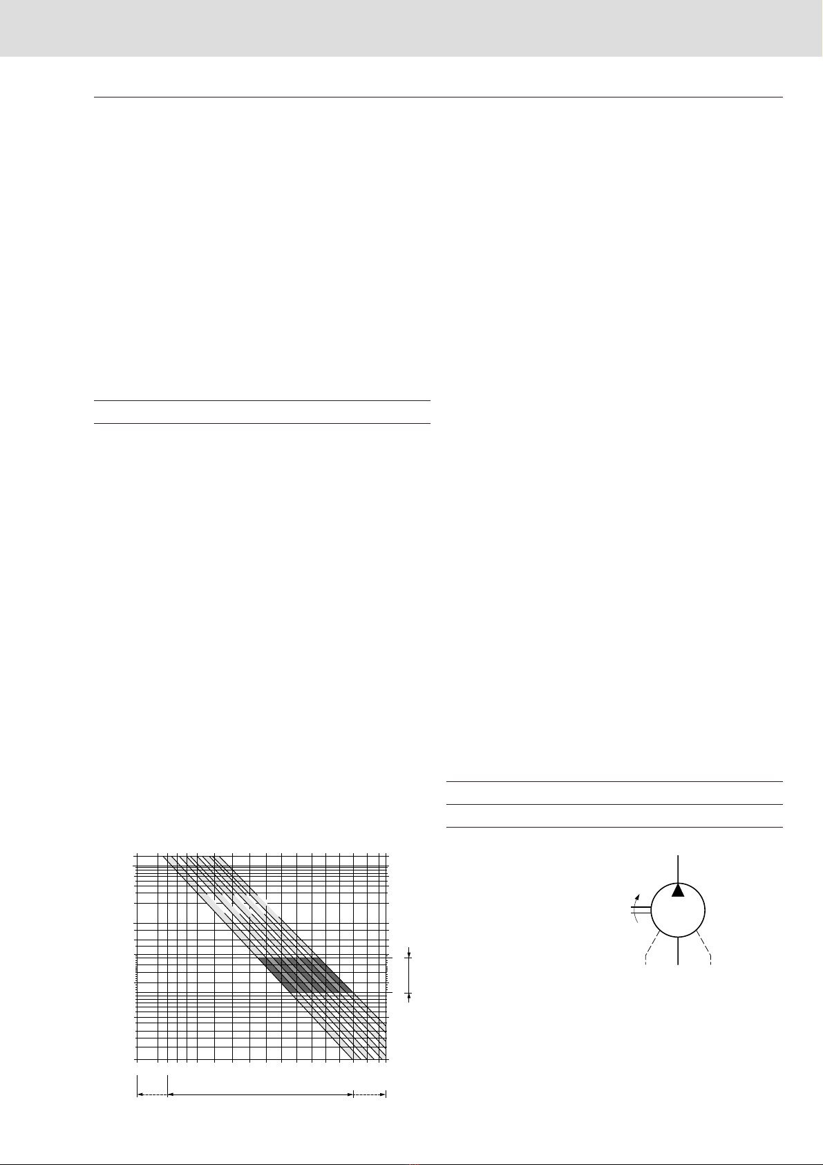
Note:
- max. perm. speed nmax perm. (speed limit)
- min. perm. pressure at port S
- admissible values for the drive shaft seal
Maximum permissible speed with increased inlet pressure
pabs at suction port S
inlet pressure p
abs
in bar
Table of values (theoretical values, without considering ηmh and ηv; values rounded)
Size 5 10 12 16 23 28 32 45 56 63 80
Displacement
Vg
cm34,93 10,3 12,0 16,0 22,9 28,1 32 45,6 56,1 63 80,4
Max. speed 1)
nmax
rpm 5600 3150 3150 3150 2500 2500 2500 2240 2000 2000 1800
Max. perm. speed with increased
nmax perm.
rpm 8000 6000 6000 6000 4750 4750 4750 4250 3750 3750 3350
input pressure pabs
Max. perm. output flow, at nmax
2)
qV max
L/min 27 32 37 49 56 68 78 99 109 122 140
Max. power ∆p = 350 bar
Pmax
kW 14,5 3)19222933414760657484
at qv max ∆p = 400 bar
Pmax
kW –22 25 34 38 47 53 68 75 84 96
Torque constants
TK
Nm/bar 0,076 0,164 0,19 0,25 0,36 0,445 0,509 0,725 0,89 1,0 1,27
Perm. torque ∆p = 350 bar
T
Nm 24,7 3) 57 67 88 126 156 178 254 312 350 445
∆p = 400 bar
T
Nm –65 76 100 144 178 204 290 356 400 508
Case volume L 0,17 0,17 0,17 0,20 0,20 0,20 0,33 0,45 0,45 0,55
Moment of inertia
J
kgm2
0,00008 0,0004 0,0004 0,0004 0,0012 0,0012 0,0012 0,0024 0,0042 0,0042 0,0072
about drive axis
Weight (approx.)
m
kg 2,5 5,4 5,4 5,4 9,5 9,5 9,5 13,5 18 18 23
Size 90 107 1 25 160 180 200 250 355 500 710 1000
Displacement
Vg
cm390 106,7 125 160,4 180 200 250 355 500 710 1000
Max. speed 1)
nmax
rpm 1800 1600 1600 1450 1450 1550 1500 1320 1200 1200 950
Max. perm. speed with increased
nmax perm.
rpm 3350 3000 3000 2650 2650 2750 1800 1600 1500 1500 1200
input pressure pabs
Max. perm. output flow, at nmax
2)
qV max
L/min 158 167 196 228 255 304 364 455 582 826 922
Max. power ∆p = 350 bar
Pmax
kW 95 100 117 135 152 181 219 273 350 497 554
at qv max ∆p = 400 bar
Pmax
kW 108 114 133 155 174 207 –––––
Torque constants
TK
Nm/bar 1,43 1,70 1,99 2,55 2,86 3,18 3,99 5,65 7,96 11,3 15,9
Perm. torque ∆p = 350 bar
T
Nm 501 595 697 889 1001 1114 1393 1978 2785 3955 5570
∆p = 400 bar
T
Nm 572 680 796 1016 1144 1272 –––––
Case volume L 0,55 0,8 0,8 1,1 1,1 2,5 3,5 7,8
Moment of inertia
J
kgm20,0072 0,0116 0,0116 0,0220 0,0220 0,0378 0,061 0,102 0,178 0,55 0,55
about drive axis
Weight (approx.)
m
kg 23 32 32 45 45 66 73 110 155 322 336
1) The values shown are valid for an absolute pressure (pabs) of 1 bar at the suction inlet S and when operated on mineral oil.
By increase of the input pressure (pabs > 1 bar) the rotational speeds can be increased to the max. admissible speeds (speed limits) (see diagram).
2) 3 % volumetric loss included 3)
∆
p = 315 bar
Calculation of size
Vg•n •ηv
Flow qV= in L/min
1000
Vg•∆p 1,59 •Vg•∆p
Torque T = = in Nm
20 π•ηmh 100 •ηmh
2 π•T •nT•nq
V•∆p
Power P = = = in kW
60 000 9549 600 •ηt
Vg= geometric displacement per rev. in cm3
T = torque in Nm
∆p = pressure differential in bar
n = speed in rpm
ηv= volumetric efficiency
ηmh= mech. -hyd. efficiency
ηt= overall efficiency
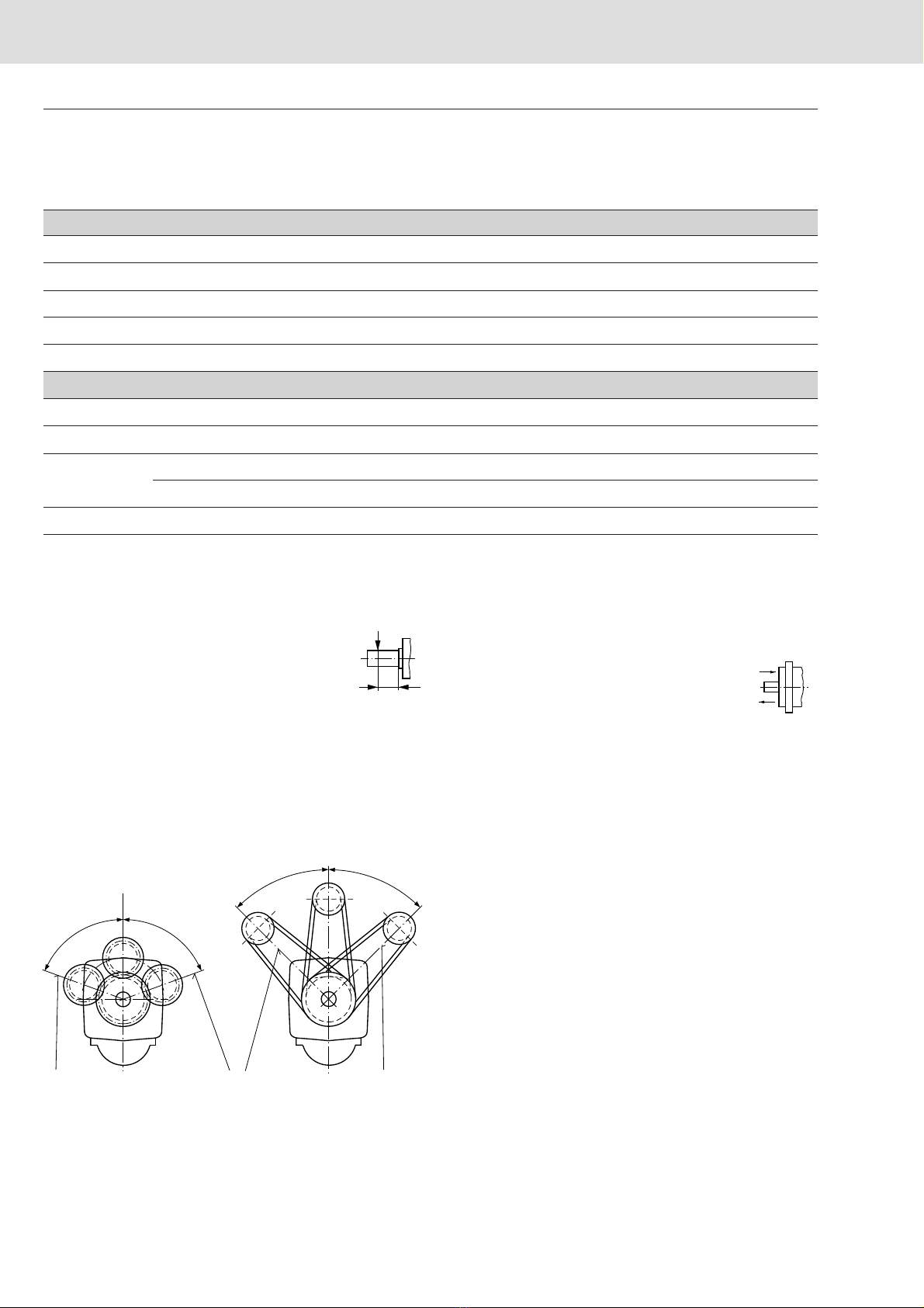
sizes 5...200
sizes 250...1000
Technical Data