REXROTH A4VG Operating instructions

Axial Piston Variable Pump
A4VG
Series 40
Repair Manual
RE 92004-01-S031/08.2015
Replaces: 09.2011
English

The data specified above serve to describe the
product. Should information be provided on use,
these are only examples of applications and
suggestions.
Information from the catalog are not assured
properties. The information given does not release
the user from the obligation of own judgment and
verification. Our products are subject to a natural
wear and aging process.
© This document, as well as the data,
specifications and other information set forth in it,
are the exclusive property of Bosch Rexroth AG.
It may not be reproduced or given to third parties
without its consent.
The cover shows an example application. The
product delivered may differ from the image on the
cover.
The original instruction manual was created in the
German language.

RE 92004-01-S031/08.2015 | A4VG Series 40 Bosch Rexroth AG 3/40
Contents
Inhalt
1 About this manual ..........................................................................................4
1.1 Related documents...................................................................................4
1.2 Abbreviations used ...................................................................................5
2 General safety instructions ...........................................................................6
2.1 Intended use .............................................................................................6
2.2 Improper use.............................................................................................6
2.3 Personnel qualifications............................................................................6
2.4 Safety instructions in this manual .............................................................7
2.5 Adhere to the following instructions ..........................................................7
2.6 Operator's obligations ...............................................................................9
3 Product description......................................................................................10
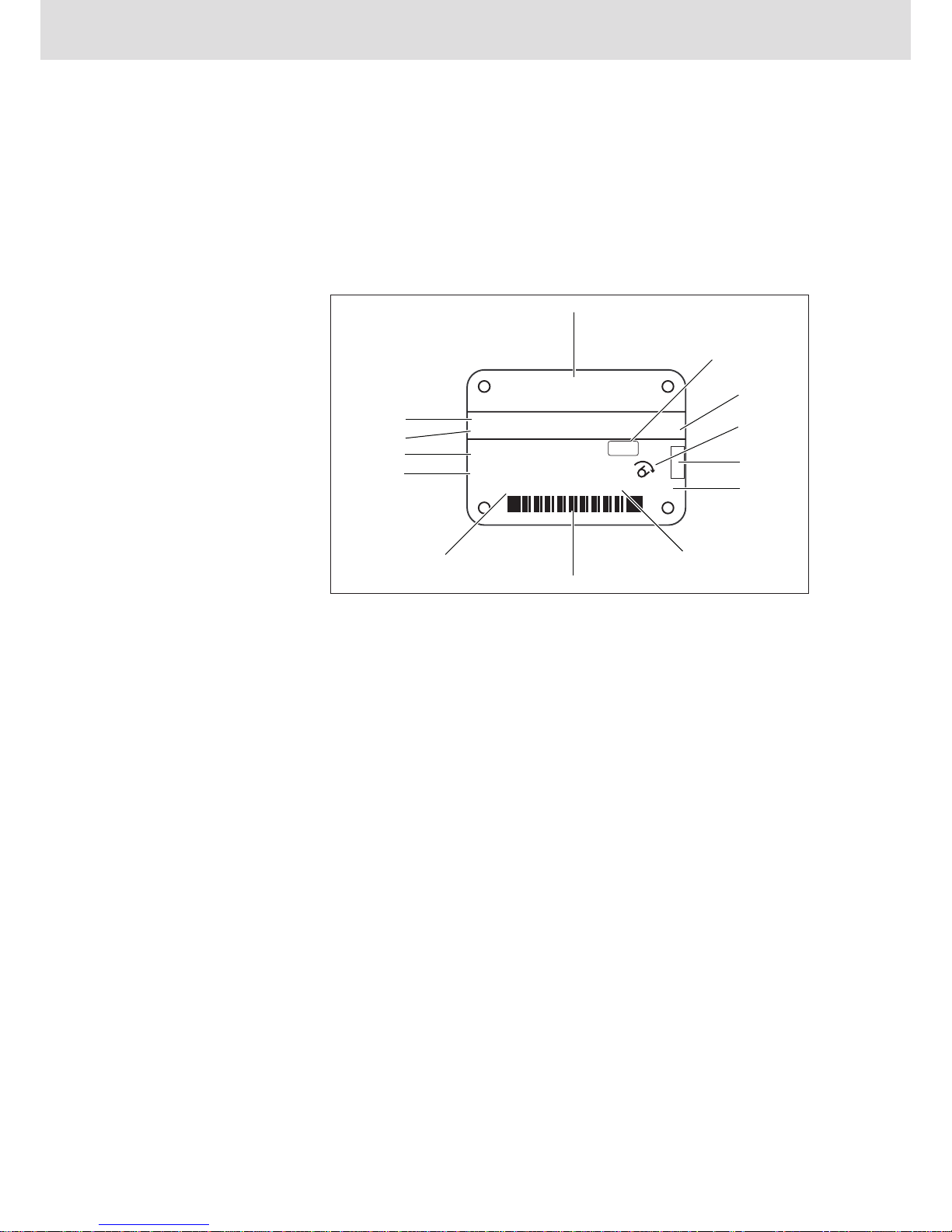
3.1 Name plate..............................................................................................10
3.2 Functional description.............................................................................11
3.3 Technical data.........................................................................................12
4 Controller.......................................................................................................13
4.1 Removing controller................................................................................13
4.2 Sealing controller ....................................................................................14
4.3 Installing the controller............................................................................15
4.4 Setting controller (hydraulic neutral position)..........................................16
5 Internal gear pump .......................................................................................17
5.1 Remove internal gear pump cover..........................................................17
5.2 Seal/install internal gear pump cover......................................................18
6 Shaft seal.......................................................................................................19
6.1 Exchange shaft seal................................................................................19
7 Valves ............................................................................................................20
7.1 Seal/replace the high pressure relief valve.............................................20
7.2 Seal/replace low pressure relief valve ....................................................22
7.3 Seal/replace pressure cut-off..................................................................24
7.3.1 Set pressure cut-off .......................................................................25
7.4 Seal control cartridge..............................................................................26
7.4.1 Set beginning of control .................................................................27
7.5 Seal shuttle valve....................................................................................28
7.6 Exchange angle position sensor.............................................................29
8 Filter ...............................................................................................................30
8.1 Mountable filter .......................................................................................30
8.2 Seal/replace filter head ...........................................................................31
9 Threaded plugs .............................................................................................32
9.1 Seal/replace threaded plugs ...................................................................32
10 Settings..........................................................................................................34
10.1 Low pressure ..........................................................................................35
10.2 High pressure..........................................................................................36
10.3 Tightening torques ..................................................................................37

4/40 Bosch Rexroth AG A4VG Series 40 | RE 92004-01-S031/08.2015
About this manual
1 About this manual
This manual contains important information on the safe and proper repair of the
axial piston variable pump A4VG Series 40.
fRead this manual completely, especially chapter "2 General safety
instructions", before working with the axial piston variable pump A4VG.
1.1 Related documents
The axial piston variable pump A4VG is a system component. Also observe the
manuals for the other system components.
Further information on the axial piston variable pump A4VG and its installation,
commissioning and operation can be found in the Rexroth documents listed in the
following table.
Table 1: Related documents
Related documents Contents
Order confirmation Contains the preset technical data of your axial piston variable
pump A4VG.
Installation drawing Contains the outer dimensions, all connections and the
hydraulic circuit diagram for your axial piston variable pump
A4VG.
Special tool catalog
RE 92004-01-S081
The product-specific special tool catalog contains the special
tools required for the axial piston variable pump A4VG.
Instruction manual
RE 92004-01-B
Contains important information for safely and properly
transporting, installing, commissioning, maintaining and
removing the axial piston variable pump A4VG.
Data sheetRE 92004 Contains the permissible technical data for the axial piston
variable pump A4VG Series 40.
Data sheet RE 90220 Describes the requirements on a mineral-oil based hydraulic
fluid and related hydrocarbons for the operation with Rexroth
hydraulic components, and assists you in selecting a
hydraulic fluid for your system.
Data sheet RE 90221 Describes the requirements on an environmentally
acceptable hydraulic fluid for operation with Rexroth hydraulic
components and assists you in selecting a hydraulic fluid for
your system.
Data sheet RE 90223 Contains additional information on the use of Rexroth axial
piston units with HF hydraulic fluids.
Data sheet RE 90300-
03-B
Contains additional information on the use of Rexroth axial
piston units at low temperatures.
Also observe the generally applicable, legal or otherwise binding regulations of
the European and national legislation and the rules for accident prevention and
for environmental protection applicable in your country.

RE 92004-01-S031/08.2015 | A4VG Series 40 Bosch Rexroth AG 5/40
About this manual
1.2 Abbreviations used
As umbrella term for "axial piston variable pump A4VG", the designation "axial
piston unit" will be used in the following.
Table 2: Abbreviations
Abbreviation Meaning
A4VG Axial piston variable pump, closed circuits
DA Automatic control, hydraulic, speed related
EP Proportional control, electric
HP Proportional control, hydraulic, pilot-pressure related
HW Proportional control, hydraulic, mechanical servo
RD Rexroth document in the German language
RE Rexroth document in the English language

6/40 Bosch Rexroth AG A4VG Series 40 | RE 92004-01-S031/08.2015
General safety instructions
2 General safety instructions
The axial piston unit has been manufactured according to the generally accepted
rules of current technology. There is, however, still a danger of personal injury or
damage to equipment if the following general safety instructions and the warnings
before the steps contained in this manual are not complied with.
fRead this manual completely and thoroughly before starting work with the
axial piston unit.
fKeep this manual in a location where they are accessible to all users at all
times.
fAlways include the instruction manual when you pass the axial piston unit on
to third parties.
2.1 Intended use
Axial piston units are hydraulic components, meaning that in their application
they are classified neither as complete nor as incomplete machines in the sense
of the EU machine directive 2006/42/EC. A component is exclusively intended to
form an incomplete or a complete machine together with other components. The
component may only be commissioned after it has been installed in the machine/
system for which it is intended.
The axial piston unit is only approved for use in hydrostatic drive systems.
fObserve the technical data, operating conditions and performance limits as
specified in the data sheet and order confirmation.
The axial piston unit is intended for professional use and not for private use.
Intended use includes having read and understood this documentation, especially
the chapter "2 General safety instructions".
2.2 Improper use
Any use other than that described as intended use shall be considered as
improper and is therefore impermissible. Bosch Rexroth AG shall accept no
liability whatsoever for damage resulting from improper use. The user shall bear
all risks arising from improper use.
Improper use of the product includes:
•using the axial piston unit in an explosive environment
•pumping non-approved fluids, e.g. water or polyurethane components.
Information about approved hydraulic fluids can be found in data
sheet RE 90223.
2.3 Personnel qualifications
Repair, installation, commissioning and operation, removal, care and
maintenance require basic mechanical, hydraulic and electrical knowledge,
as well as knowledge of the appropriate technical terms. For transporting and
handling the product, additional knowledge is necessary with regard to working
with a lifting device and the corresponding attachment equipment. In order to
ensure operating safety, these activities may therefore only be carried out by
qualified personnel or an instructed person under the direction and supervision of
qualified personnel.
Qualified personnel are those who can recognize possible hazards and institute
the appropriate safety measures due to their professional training, knowledge,
and experience, as well as their understanding of the relevant regulations

RE 92004-01-S031/08.2015 | A4VG Series 40 Bosch Rexroth AG 7/40
General safety instructions
pertaining to the work to be done. Qualified personnel must observe the rules
relevant to the subject area.
2.4 Safety instructions in this manual
In this manual, there are safety instructions before the steps whenever there
is a danger of personal injury or damage to equipment. The described danger
prevention measures must be observed.
Safety instructions are set out as follows:
Type of danger!
Consequences
fPrecautions
•Safety signs: (warning triangle): draw attention to danger
•Signal word: identifies the degree of the danger
•Type of danger: identifies the type or source of the danger
•Consequences: describes what occurs if the safety instructions are not
complied with
•Precautions: states how the danger can be avoided.
The signal words have the following meaning:
Signal word Application
DANGER! Indicates an imminently hazardous situation which, if not
avoided, will certainly result in death or serious injury.
WARNING! Indicates a potentially hazardous situation which, if not
avoided, could result in death or serious injury.
CAUTION! Indicates a potentially hazardous situation which, if not
avoided, could result in minor or moderate injury or damage to
equipment.
If this information is disregarded, the operating procedure may
be impaired.
2.5 Adhere to the following instructions
•Observe the regulations for accident prevention and environmental protection
for the country where the product is used and at the workplace.
•Only operate Rexroth axial piston units in good technical order and condition.
•Use the product only within the performance range provided in the technical
data.
•Repairs to the axial piston unit may only be performed by authorized, skilled
and instructed personnel.
•Persons who repair, install, commission, operate, remove or maintain Rexroth
products must not consume any alcohol, drugs or pharmaceuticals that may
affect their ability to respond.
•The warranty applies only to the delivered configuration.
SIGNAL WORD!
General instructions

8/40 Bosch Rexroth AG A4VG Series 40 | RE 92004-01-S031/08.2015
General safety instructions
•The warranty is rendered void if the product is incorrectly repaired, installed,
commissioned or operated, and also if not used as intended and/or handled
improperly.
•Do not expose the product to any mechanical loads under any circumstances.
Never use the product as a handle or step. Do not place/lay any objects on it.
•The noise emission of axial piston units depends on speed, operating pressure
and installation conditions. The sound pressure level may rise above 70 dBA
during normal application conditions. This can cause hearing damage.
– Always wear hearing protection while working in the vicinity of the operating
axial piston unit.
•The axial piston unit heats up during operation to such an extent that you can
be burnt by touching it.
– Allow the axial piston unit to cool down sufficiently before touching it.
– Wear heat-resistant protective clothing, e. g. gloves.
•Hydraulic fluid is easily flammable.
– Keep open flames and ignition sources away from the axial piston unit.
•Make certain that the lifting device has adequate lifting capacity. The weight can
be found in chapter "5 Transport and storage" of instruction manual
RE 92004-01-B.
•Make sure the relevant system component is depressurized and voltage-free
before removing the product or when disconnecting plugs. Protect the system
against being energized.
•Before removing, place a drip tray under the axial piston unit to prevent
environmental pollution through hydraulic fluid that may escape.
•Before repairing, ensure that all fluids are removed from the axial piston unit.
•During installation, provide for absolute cleanliness in order to prevent
contaminants, such as dirt, welding beads or metal cuttings, from getting into
the components and causing product wear or malfunctions.
•Special tools are required for the repair. Repair without the required special
tools is not permissible.
•Use only original spare parts from Rexroth for the repair.
•Replace the seals with new ones during the repair operation.
•All components must be clean and undamaged.
•Damaged components must not be reused.
•It is not permissible to retap threads.
•It is not permissible to remachine boreholes.
•Observe the notes in instruction manual RE 92004-01-B.
•Plug all openings with the appropriate protective equipment in order to prevent
detergents from penetrating the system.
•Never use solvents or aggressive detergents. Use only water and, if necessary,
a mild detergent to clean the axial piston unit.
•Do not point the power washer at sensitive components, e.g., shaft seal ring,
electrical connections and electrical components.
•Dispose of the product and the hydraulic fluid according to the currently
applicable national regulations in your country.
During transport
During removal
During repair
During installation and
commissioning
During cleaning
Disposal

RE 92004-01-S031/08.2015 | A4VG Series 40 Bosch Rexroth AG 9/40
General safety instructions
2.6 Operator's obligations
The operator of the Rexroth axial piston unit must provide personnel training on a
regular basis regarding the following subjects:
•Observation and use of the instruction manual and the legal regulations
•Intended use and operation of the axial piston unit
•Observation of the instructions from the factory security offices and of the work
instructions from the operator
Rexroth offers training support for special fields. You can find an overview of
the training contents on the Internet at: http://www.
boschrexroth.de/didactic.

10/40 Bosch Rexroth AG A4VG Series 40 | RE 92004-01-S031/08.2015
Product description
3 Product description
This chapter provides a general overview of the functionality of the variable pump.
Familiarize yourself with the contents of this chapter before you begin working on
a variable pump.
3.1 Name plate
The variable pump can be identified by means of the name plate:
TYP:
MNR:
SN:
FD: Rotation:
D-89275 Elchingen
Made in Germany
A4VG110EP2D0000/40MRND6T21F0000AS00-0
R90XXXXXXX SC: X
12345678
Rexroth
07W28
n = XXXX min-1 P = XXX kW m: XXX kg
7202
1
2
3
4
5
6
7
8
9
10
11
12
13
Fig. 1: Name plate
The name plate contains the following information:
1 Manufacturer
2 Internal plant designation
3 Sample category (optional)
4 Direction of rotation (viewed on
drive shaft) – here: clockwise
5 Specified area for test stamp
6 Weight (optional)
7 Power (optional)
8 Bar code
9 Rotational speed (optional)
10 Production date
11 Serial number
12 Material number of the
axial piston unit
13 Ordering code
Ensure that the type and nominal size of the variable pump to be repaired
correspond to this repair manual.

RE 92004-01-S031/08.2015 | A4VG Series 40 Bosch Rexroth AG 11/40
Product description
3.2 Functional description
In order for you to be in a position to identify problems in a variable pump and to
perform repairs effectively, knowledge of the functionality and the overall structure
of the device is essential.
This section gives you a high level overview.
The variable pump is an axial piston variable pump in a swashplate design for
hydrostatic drives in closed circuit.
The volumetric flow is proportional to the drive speed and the displacement. The
flow rate can be varied continuously by adjustment of the swashplate.
A detailed functional description is contained in the product-specific instruction
manual RE 92004-01-B.
The following sectional drawing shows the design of the A4VG series 40 axial
piston pump schematically.
@
Fig. 2: Sectional drawing of variable pump
1 Drive shaft
2 Retaining plate
3 Stroke piston
4 Controller
5 Control plate
6 Internal gear pump
7 Suction port
8 Cylinder
9 Piston
10 Slipper pad
11 Swashplate

12/40 Bosch Rexroth AG A4VG Series 40 | RE 92004-01-S031/08.2015
Product description
3.3 Technical data
The technical data of the variable pump can be found in the order confirmation.
These are supplemented by the technical data sheet. Technical data sheet
RE 92004 applies to the A4VG variable pump.

RE 92004-01-S031/08.2015 | A4VG Series 40 Bosch Rexroth AG 13/40
Controller
4 Controller
The material numbers for the special tools are to be found in the Special Tool
Catalog RE 92004-01-S081.
If not explicitly specified, permissible tightening torques for the bolted
connections are to be found in Chapter "10 Settings".
4.1 Removing controller
This section describes how you remove the controller from the pump.
There is a wide variety of controllers.
Please note that the removal of only one such controller is shown here
exemplarily.
@@
Fig. 3: Controller
1 Fixing screws
2 Controller
3 Pump case
To remove the controller:
1. Loosen and remove the fixing screws (1) of the controller (2).
2. Detach the controller (2) from the pump casing (3).
Procedure

14/40 Bosch Rexroth AG A4VG Series 40 | RE 92004-01-S031/08.2015
Controller
4.2 Sealing controller
This section describes how you seal the controller.
There is a wide variety of controllers.
Please note that the sealing of only one such controller is shown here
exemplarily.
@
Fig. 4: Controller
1 Fixing screws
2 Cover
3 Seal
4 Controller
5 Seal
6 Pump case
7 Mounting nut
8 O-ring
9 Coil
To replace the seals:
1. Loosen and remove the fixing screws (1) of the controller (4).
2. Remove the cover (2) and the seals (3+5) from the controller (4).
3. Check the seals, the sealing surfaces and the case for damage, wear and
contaminants.
4. Exchange the seals (3+5).
The individual components and the removal/installation of the left-hand and
right-hand solenoids are identical.
5. Loosen and remove the mounting nuts (7) on the coil (9).
6. Check the O-ring and O-ring groove for damage, wear or contaminants.
7. Exchange the O-ring (8) for a new one.
8. Tighten the mounting nuts (7) with 5 Nm.
Procedure

RE 92004-01-S031/08.2015 | A4VG Series 40 Bosch Rexroth AG 15/40
Controller
4.3 Installing the controller
This section describes how you install the controller.
There is a wide variety of controllers.
Please note that the installation of only one such controller is shown here
exemplarily.
@@
Fig. 5: Controller
1 Fixing screws
2 Controller
3 Pump case
To install the new or newly-sealed controller:
1. Using two fixing screws (1) center the seals, cover and the controller (2) on
the pump case (3).
2. Screw in the two remaining fixing screws (1).
Tighten the fixing screws crosswise according to the specified tightening
torque - see Chapter "10 Settings".
After installation of the controller, the hydraulic neutral position must be set
anew.
Procedure

16/40 Bosch Rexroth AG A4VG Series 40 | RE 92004-01-S031/08.2015
Controller
4.4 Setting controller (hydraulic neutral position)
This section describes how you set the hydraulic neutral position.
There is a wide variety of controllers.
Please note that the configuration of only one such controller is shown here
exemplarily.
Risk of injury!
The following works on the variable pump are dangerous.
fPay close attention to the safety instructions (See Chapter "2 General safety
instructions").
fWhile working with hazardous materials (for example, hydraulic fluids), always
wear safety gloves and safety glasses.
9
9
Fig. 6: Hydraulic neutral position
1 Clamping screw 2 Eccentric pin
To set the hydraulic neutral position:
1. Connect pressure gauges (max. 40 bar) to ports X1and X2.
The oil temperature in the closed circuit should be approx. 65 °C.
2. Secure the vehicle against unintended motion and then switch the control
device to the neutral position.
Test speeds for the engine: Idle and maximum rpm.
3. At both speeds check that both pressure gauges on the ports X1and X2give
the same reading.
4. If the pressure values do not agree, loosen the clamping screw (1).
5. Turn the eccentric pin (2) until the same pressure reading is indicated on both
gauges.
Do not turn the eccentric pin on the control unit beyond 90°.
6. Tighten the clamping screw (1).
WARNING!
Procedure

RE 92004-01-S031/08.2015 | A4VG Series 40 Bosch Rexroth AG 17/40
Internal gear pump
5 Internal gear pump
The material numbers for the special tools are to be found in the Special Tool
Catalog RE 92004-01-S081.
If not explicitly specified, permissible tightening torques for the bolted
connections are to be found in Chapter "10 Settings".
5.1 Remove internal gear pump cover
This section explains how you remove the cover on the internal gear pump.
@@
Fig. 7: Internal gear pump cover
1 Fixing screws
2 Internal gear pump cover
3 Intermediate plate
4 Pump case
The pump case is foreseen for two nominal sizes.
These constitute a nominal size pair e.g. (85/110). The larger nominal size
(110) is equipped with a standard intermediate plate and the smaller nominal
size is without intermediate plate. Please note that the replacement of the
seals with intermediate plate is presented here.
To remove the internal gear pump cover:
1. Loosen and remove the fixing screws (1) of the internal gear pump cover (2)
on the pump case (4).
2. Remove the internal gear pump cover (2) and the intermediate plate (3).
Procedure

18/40 Bosch Rexroth AG A4VG Series 40 | RE 92004-01-S031/08.2015
Internal gear pump
5.2 Seal/install internal gear pump cover
This section describes how you seal/install the internal gear pump cover.
@@
Fig. 8: Internal gear pump cover
1 Fixing screws
2 O-ring
3 Internal gear pump cover
4 Intermediate plate
5 O-ring
6 Kant seal
7 O-ring
8 Pump case
To replace the seals:
1. Check the Kant seal, O-rings and sealing surfaces for damage, wear and
contaminants.
2. Exchange the Kant seal (6) and O-rings (2+5+7) for new ones.
3. Screw the internal gear pump cover (2) and the intermediate plate (3) with the
fixing screws (1) to the pump case (4).
Tighten the fixing screws crosswise according to the specified tightening
torque - see Chapter "10 Settings".
Procedure

RE 92004-01-S031/08.2015 | A4VG Series 40 Bosch Rexroth AG 19/40
Shaft seal
6 Shaft seal
The material numbers for the special tools are to be found in the Special Tool
Catalog RE 92004-01-S081.
If not explicitly specified, permissible tightening torques for the bolted
connections are to be found in Chapter "10 Settings".
6.1 Exchange shaft seal
This section explains how you exchange the shaft seal.
Required special tools: See Special Tool Catalog RE 92004-01-S081.
@
Fig. 9: Exchange shaft seal
1 Retaining ring
2 Shaft seal
3 Bearing flange
To replace the shaft seal:
1. Remove the retaining ring (1).
2. Using the demounting pliers remove the shaft seal (2) from the bearing
flange (3).
3. Lightly grease the new shaft seal between the sealing- and dust lip to prevent
dry running.
Mask the splines on the drive shaft to prevent damage to the shaft seal during
installation.
4. Using the installation bush, press the shaft seal (2) into the bearing flange (3)
as far as it will go.
5. Install the retaining ring (1) in such a way that it seats into the corresponding
slot.
6. Remove the masking on the drive shaft.
Procedure

20/40 Bosch Rexroth AG A4VG Series 40 | RE 92004-01-S031/08.2015
Valves
7 Valves
The material numbers for the special tools are to be found in the Special Tool
Catalog RE 92004-01-S081.
If not explicitly specified, permissible tightening torques for the bolted
connections are to be found in Chapter "10 Settings".
7.1 Seal/replace the high pressure relief valve
This section describes how you seal/replace the high pressure relief valve.
Depending on the model, valves not shown in the diagram may be present on
your unit.
The variable pump is equipped with two high pressure relief valves. The same
steps are required to seal each of the high pressure relief valves.
@
Fig. 10: High pressure relief valve
1 Threaded plug
2 O-ring
3 Pressure spring
4 O-ring
5 Valve insert
6 High pressure relief valve
7 Pump case
Table of contents
Other REXROTH Water Pump manuals
Popular Water Pump manuals by other brands

WIKA
WIKA 6 Series operating instructions

Ulvac
Ulvac VPC-051 user manual

Franklin Electric
Franklin Electric Little Giant TPS instruction sheet

Sagola
Sagola DM1/300 Instruction manual / spare parts list

Winter
Winter WHM Series operating manual

Wilo
Wilo VeroLine IPH Series Installation and operating instruction