RF Mogul Eagle User manual

Owner’s Manual
Eagle RV TV Antenna
Please have the following information available
when contacting Tech. Support.
Controller Serial #_______________________________
Antenna Serial # _______________________________
Date of Purchase: _______________________________
Installer’s Name: ________________________________

The Eagle TV Automatic Antenna System provides RV customers the
choice of their preferred Satellite TV provider all on the same
mount. The viewing experience is HDTV and 4K UltraHD utilizing
multiple receiver's and DVR’s simultaneously.
It is a true at home experience in the comfort of your RV!
Please take the time to read this manual in its entirety before
installing or operating your new TV Satellite antenna.
Thank you for purchasing an RF Mogul Product!

2 | P a g e
RF MOGUL 3604 South Via Terra Salt Lake City, Utah 84115 Sales: 801-895-3392 Email: [email protected] Rev 8/20
Table of Contents
Safety and Warnings ………………………..………………………………………………….………….……..3
Clearance Requirements ……………………………………………….…….…………..…….………….…..4
Eagle TV Parts and Movement Definitions ………………………..….……..……...….………….….5
Eagle TV Assembly Instructions …………………………………………………....……………....……….6
Eagle TV Installation Instructions …………………………………….………..…………..….…….…….14
DirecTV SWM Connection Diagram…………………………………….…..……………….……………..19
SHAW Connection Diagram………………………………………………..…….……………..…….……...20
Dish DPH LNB Connection Diagram…………………………….…….………..………………..………..21
Dish Hopper-3 Connection Diagram………………………..………………..…………………..…..…..22
Controller Operations …………….…………………….……………….………………..…….….….……….23
Appendix ……………………………………………….………………………….……………….…………….…..27
Warranty and Registration.………………….……………………………….…………………….….……..28

3 | P a g e
RF MOGUL 3604 South Via Terra Salt Lake City, Utah 84115 Sales: 801-895-3392 Email: [email protected] Rev 8/20
Safety and Warnings
1. Do not stand in front of an antenna during operation.
2. Follow all Instructions and Warnings. Set up and operate RFM products in accordance
with the instructions.
3. Tighten all coax cables by hand only. If you over tighten with a wrench you may damage
your equipment.
4. Loosely wrap all cables and power supply! Do not tightly bind or bend any coax or control
cables as you may disrupt a positive connection with your satellite service.
5. Do not attempt to install this system in the rain or under any wet conditions. Moisture
may affect electronics and void your warranty.
6. Do not paint this antenna. Painting the antenna will void your warranty.
7. Power must be disconnected or unplugged prior to disconnecting or connecting any
cables.
8. Vehicle construction varies greatly. If you are unsure of how to safely drill through your
vehicle roof obtain a professional installation.
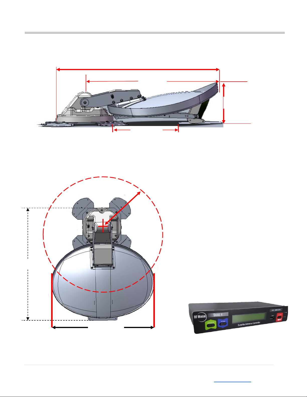
9. Prior to installing the antenna system on a vehicle, verify there is enough operating space.
The antenna rotates in a 360-degree circle projecting 26 inches from the center of the
circular antenna base.
10. Pay attention to protrusions from the roof such as air conditioning units, rack structures
or other antennas before installing this antenna.
11. Our interconnecting cables come standard 25 feet. Ensure that there will be no more than
20 feet between electronics and the antenna on the roof.
12. The antenna weight should be distributed over support or cross beams. A mounting
surface that is not strong enough to support the weight of the antenna may cause
structural damage to your vehicle.
13. If not using an RFM antenna for long periods of time, and the antenna system is kept out
in the elements of the outdoors, it is recommended that you operate the system every 6
months and at a minimum once a year, to keep all moving parts in good working order.
OBSTRUCTIONS DURING OPERATION
The Eagle TV Satellite requires an unobstructed view of the southern sky for the best signal reception.
Buildings and trees are examples of such obstructions that may prevent strong signal strength. Also
check that there are no obstructions (such as tree limbs) above the antenna that will prevent it from
raising. The Eagle Antenna will reach 33.5” above the roof to which it is mounted.

4 | P a g e
RF MOGUL 3604 South Via Terra Salt Lake City, Utah 84115 Sales: 801-895-3392 Email: [email protected] Rev 8/20
Clearance Requirements
The arm of the Eagle antenna extends 26” from the center of the base. Ensure there is adequate rotational
clearance for the antenna to safely operate.
37 Inches
8.5 Inches
33.5 Inches
Rotational clearance from center
rotation point is 26 inches when dish is
elevated and rotating. This is a safety
zone. Anything higher than 6 inches
within this zone is at risk.
10" Wide x 6” Deep x 2” High
13.5 Inches
Distance for installing LNB
Landing Plate
Safety Zone
26 Inch radius
29 Inches
37 inches
CONTROLLER Dimensions

5 | P a g e
RF MOGUL 3604 South Via Terra Salt Lake City, Utah 84115 Sales: 801-895-3392 Email: [email protected] Rev 8/20
Eagle TV Parts and Movement Definitions
Elevation (EL)
Raises Up and Down
Azimuth (AZ)
Rotates CW and CCW
Skew (SK)
Reflector Tilt Up and Down
Stowed
(travel
position)
Items Included with the System:
1 ea. EAGLE Controller
1 ea. Mount base assembly
1 ea. Reflector
1 ea. LNB Arm Assembly w/LNB
2 ea. Stow Brackets
1 ea. LNB Landing Plate
25 ft Control Cable
1 ea. Clam Shell
1 ea. Weather Cover
6 ea. 1/4x20x3/4 screws
1 ea. Connector, green, 12 pins
1 ea. Power Supply, 12 VDC 7 amp
1 ea. Owner’s Manual
Reflector
or Dish
LNB Arm Assembly
Elevation Arms
Mount Base
and covers
Mounting Feet
LNB (DirecTV SWM shown)
Note: LNB’s vary by shape
depending on your service
provider.
Stow
Brackets
Control & Coax
Cables
Mount Movements
Eagle Controller
Clam Shell
(For roof
entry)
Weather cover
connector box

6 | P a g e
RF MOGUL 3604 South Via Terra Salt Lake City, Utah 84115 Sales: 801-895-3392 Email: [email protected] Rev 8/20
Eagle TV Assembly Instructions
Mounting the Reflector and the LNB Arm to the Base Assembly
1. Your Eagle Antenna will be shipped in 2 separate boxes. A Reflector box and a Mount box.
2. Locate the Control Cable and Mounting Hardware enclosed in the weather covered bag in the Mount Box
and remove the Control Cable from the bag.
Reflector Box
Mount Box
Control Cable
Control Cable and Mounting hardware

7 | P a g e
RF MOGUL 3604 South Via Terra Salt Lake City, Utah 84115 Sales: 801-895-3392 Email: [email protected] Rev 8/20
3. Splice and bare the cable end with a razor blade being careful NOT to cut into the wires. Cut off the excess
cable cover using needle nose plyers. Using wire strippers, strip ½” off the exposed colored wires as shown
below.
Cut off excess cable covering
Strip colored wire ends ½”

8 | P a g e
RF MOGUL 3604 South Via Terra Salt Lake City, Utah 84115 Sales: 801-895-3392 Email: [email protected] Rev 8/20
4. Remove the Mount Assembly from the Mount box and position it onto a level surface. Plug the Control
Cable into the Mount Cable as shown.
5. Using a drill battery or a 9 Volt battery for a power source, locate the RED and ORANGE wires on
the Control Cable end. (Refer to instructions in Figure 1 page 27)
a. Touch the RED and ORANGE wires to the Plus and Minus poles on your 9 Volt battery
or power source.
b. Upon touching the DC power source, if the mount arms do not move upward, then
reverse the wires on the contacts of the DC voltage source.
6. Raise the mount to about 20 degrees past vertical (this will make attachment of the Reflector
easier).
Note: If using DirecTV or Dish DPH LNB only a single coax is needed for the install. To protect the
other 2 coaxes (included on the antenna mount) you can tuck them into the skew mechanism.
Make sure the color code of the coax connected to the LNB is the same as the color code connected
at the antenna base.
Fill all coax connectors with dielectric grease to prevent corrosion!
Plug together the 2 cable ends
Mount Assembly
Skew
Mechanism

9 | P a g e
RF MOGUL 3604 South Via Terra Salt Lake City, Utah 84115 Sales: 801-895-3392 Email: [email protected] Rev 8/20
7. Feed the Coax Cables harness (split loom) through the pre-drilled hole in the reflector from the
back side.
8. Attach the Reflector loosely to the Brackets on the Mount in the top 2 holes using 2 of the
¼”-20 x ¾” Philips SS screws that are provided. Align the remaining 4 holes then tighten the top 2.
Split Loom

10 | P a g e
RF MOGUL 3604 South Via Terra Salt Lake City, Utah 84115 Sales: 801-895-3392 Email: [email protected] Rev 8/20
9. Attach the LNB Arm (choose your direction on Page 13 based on your provider) loosely to the
Reflector using 4of the ¼”- 20 x 3/4” screws provided. The LNB Arm should be able to be pivoted
upwards into the Reflector after it is attached. Tighten all 6 screws using a #3 Philips screwdriver.
10. To install the LED Lights onto the reflector, Splice the Black and Red wires using the Scotch-Lok
connectors (red button). It is not necessary to strip the wires. Place the ends of the wires (red to red,
black to black) deeply into the connector and pinch with pliers. This will connect the LED’s that will
reflect onto the dish at night. (If you choose not to connect the LED lights, remove, or securely isolate
as they have constant 12VDC.) Tuck the Scotch-Lok connectors through the hole in the dish.
LED Connector

11 | P a g e
RF MOGUL 3604 South Via Terra Salt Lake City, Utah 84115 Sales: 801-895-3392 Email: [email protected] Rev 8/20
11. Route the Cable Loom down either side of the LNB Arm and secure with Cable Ties (provided).
12. Tuck any excess Cable Loom back through the Reflector. Leave enough out to prevent binding.
13. Lift on the LNB Arm making sure there is no stress on the Cable Loom as the arm is lifted into the
center of the dish.
14. Remove and save the two (2) inner screws on the LNB Bracket located at the end of the LNB Arm.
(Applies to DirecTV may differ w/ Dish Slimline Eastern & Western Arc LNB) These screws are used to
attach the LNB.
Remove two inner screws

12 | P a g e
RF MOGUL 3604 South Via Terra Salt Lake City, Utah 84115 Sales: 801-895-3392 Email: [email protected] Rev 8/20
15. Loosen the two (2) outer screws of the LNB Bracket. Do not remove, just loosen to accommodate
the insertion of the LNB between the brackets.
16. Route the LNB cables “through” the LNB brackets and attach to the LNB securely, but do not use
excessive force to tighten these connectors or damage to the coax cable may occur. Slide the LNB
into the LNB Brackets and insert the two (2) screws back into the LNB.
Loosen the 2 outer screws

13 | P a g e
RF MOGUL 3604 South Via Terra Salt Lake City, Utah 84115 Sales: 801-895-3392 Email: [email protected] Rev 8/20
17. Attach the two (2) LNB Arm Stow Brackets on the inside of the LNB arm assembly (see diagram
below to determine direction arm brackets and LNB should be placed) using the screws provided and
then secure both the two inner and outer screws that hold the LNB into place.
Direction of the Stow Brackets into LNB Arm Assembly
When the dish is STOWED it will apply pressure to these brackets to prevent it from vibrating while
traveling. Slide the Stow Bracket in the direction of the arrow into the LNB Arm Assembly.
It is important that the brackets are properly orientated during assembly.
LNB Bracket
Dish Network
Bell TV
DirecTV
SHAW
Stow Bracket
LNB Arm Assembly

14 | P a g e
RF MOGUL 3604 South Via Terra Salt Lake City, Utah 84115 Sales: 801-895-3392 Email: [email protected] Rev 8/20
Eagle TV Installation
Roof Mounting and Sealing
Materials Provided
1. RF Mogul Antenna
2. Antenna control unit with power supply
3. Pre-terminated control cable for ACU-1
4. Clam Shell Cover
5. Weather Cover Junction Box
6. LNB Landing Plate
7. ¾” Mounting screws
8. 10 Black Wire ties
9. 10 Black wire cable clips and screws
Materials Not Provided
1. 9 V DC Battery
2. 7/16” wrench
3. ¼ inch nut driver
4. Small diameter drill bit long enough to go through the roof of your coach
5. Small standard (jewelers) screwdriver
6. 1” hole saw
7. 1 power strip or uninterruptible power supply suitable for your application
8. Appropriate bit for the mounting screws
9. 1-2 tubes of DICOR self-leveling sealer (available at most RV dealerships)
10. 1 tube of dielectric compound (Boss Products Accumetric, LLC www.bossproducts.com)
11. 1 tube clear silicone #315 (Boss Products www.bossproducts.com )
12. Split loom cable wrap

15 | P a g e
RF MOGUL 3604 South Via Terra Salt Lake City, Utah 84115 Sales: 801-895-3392 Email: [email protected] Rev 8/20
1) Identify the install location and verify the area is clean and clear of debris.
Caution: Mounting surface must be clean for the antenna to properly seal to the roof.
This will help prevent water penetration and allow the antenna to sit level.
Caution: The Eagle antenna must be oriented toward the front of the vehicle. The
antenna reflector must face the rear of vehicle it is being installed on (see photo
after step 12) to prevent damage to the antenna system due to wind forces while
the vehicle is in motion.
2) Identify a cabinet location in the vehicle where the electronics (Controller) will be housed and
where the pass thru hole to the roof will be cut.
3) Verify at least 2 of the mounting feet are over and able to secure to the support beams on the
vehicle.
Caution: A mounting surface that is not strong enough to support the weight of the
antenna may cause structural damage to your vehicle.
4) Inspect the interior structure for existing wires or tubing where the screws will penetrate the roof
of the vehicle.
Caution: Screws that penetrate any existing wires or tubing in the vehicle may cause
damage to existing equipment or be a hazard to personnel.
5) Carefully lift the Antenna on to the roof of the vehicle and to the area of install.

16 | P a g e
RF MOGUL 3604 South Via Terra Salt Lake City, Utah 84115 Sales: 801-895-3392 Email: [email protected] Rev 8/20
Caution: 2 MAN LIFT IS RECCOMENDED TO PREVENT INJURY.
6) Elevate the antenna using a 9 Volt DC battery or a power source to make the system
maneuverable for installation and so that you can have access to the drill holes on the feet.
a. Touch the RED and ORANGE wires to the Plus and Minus poles on your 9 Volt
battery or Power source.
b. Upon touching the DC power source, if the mount arms do not move upward,
then reverse the wires on the contacts of the DC voltage source.
7) Trace the holes where you will insert the screws on the roof to help as a guide.
Caution: As a bare minimum you must put a screw in all pre-drilled holes on the
mount feet. In the event the pre-drilled holes do not align with your support
structure, it is highly recommended that you drill extra holes as needed prior to
using Dicor sealer.
8) Put Dicor sealer over the locations of the predrilled holes and on the mounting feet.
9) Lift the antenna over the location where the antenna screws will penetrate the mounting surface
(including any extra drilled screw locations) and lower the antenna mount feet onto the mounting
surface. (Rotate feet as necessary from shipped position) and secure the mount feet to the roof
using the mounting screws you selected.
10) Liberally coat the screw heads and around the mount feet with Dicor to prevent water
penetration. As shown below.
11) Install the LNB Landing plate where the LNB Arms and LNB will stow on the roof (Approximately
10-12 inches in front of the antenna base) with screws. (See photo after step 12 as a reference)
Dicor around the plate and on the screw heads.
12) Using a small diameter drill bit make a small pilot hole in the roof where the cabling will pass
through into the control cabinet in the vehicle.

17 | P a g e
RF MOGUL 3604 South Via Terra Salt Lake City, Utah 84115 Sales: 801-895-3392 Email: [email protected] Rev 8/20
13) Drill the larger 1-inch hole using the 1-inch drill bit or hole saw.
Caution: Proceed slowly, 1 layer at a time, verifying after each layer is removed
that no cables or other critical components will be damaged by the hole.
14) Remove the green molex connector (use the small jewelers screwdriver to remove the small
screws) from the Control Cable if you have already installed it to the end of your control cable in
order to pass the cable through the hole. If you haven’t connected it but have spliced it and
striped the wires, you may cut the end off to have a clean edge then pass the control cable
through the hole, resplice and strip the ends again (wires for the control cable should be stripped
back 1/2” from the end and bent back to make a ‘V’ with the cable and then insert into the green
molex connecter) then connect it to the controller and place it in a cabinet. You will also pass the
coax cable(s) 1-3 (depending on your service provider) through the roof entry hole into the
vehicle. Do not pull the cables taut! Leave 2-3 foot of cable on the roof for the next steps.
(Attach the Green 12 Pin Connector in accordance with instructions on the bottom
of the Eagle Controller or figure 2 on pg. 27) If the wires are placed too far into the
connector, it will clamp down on the outer plastic shielding, and will not make
good connection to the wire. Failure to do this correctly will cause your satellite
system to malfunction or cause erratic behavior.
15) Mount the Weather Covered antenna junction box near where the cables connect (within the
‘clearance zone’near the mount feet) using screws. Use photo at the top of this page as a
reference.
16) Liberally apply Dielectric compound grease to coax cable ends. Connect the controller cable and
coax cables and store the connectors inside the weather cover junction box.
Pass through
into vehicle
with the Clam
shell to cover
the entry hole.
Weather Cover
junction box is
to protect cable
connections.
Service loop
allow future
cable repairs.
LNB
Landing
Plate
Reflector facing to
the rear of Vehicle
when installing!

18 | P a g e
RF MOGUL 3604 South Via Terra Salt Lake City, Utah 84115 Sales: 801-895-3392 Email: [email protected] Rev 8/20
17) Make a 1-2 foot ‘Service loop’ with the cable wires and secure the looped wires on the roof with
wire clips or cable clamps.
18) Secure the wires with cable clamps every 12-16 inches from the antenna junction box working
towards the cable entry hole into the vehicle to eliminate cable movement.
19) Coat all cable clamps and screws with Dicor to prevent water leakage.
20) Put silicone in the cable hole (NOT Dicor as it is self-leveling and will seep into the hole) to fill the
void and help prevent water penetration. Once the silicone has set use the Dicor around the
silicone to water seal the cable penetration area.
21) Pull any excess cables through the pass-through entry hole and then screw the Clam Shell cover
over the hole. This will prevent water entry. Cover the outer seam of the cover and all screws
with Dicor.
Caution: It is advisable to place the open end of the Clam Shell towards the rear
end of the vehicle to prevent pressure on the opening while driving.
Cut your Control and Coax cables to length inside the vehicle. Insert the cables into
split loom cable wrap. Leave enough length of both cables to be able to remove the
Eagle II Controller from the cabinet with ease should the occasion arise. Loosely
wrap excess cable into a coil and secure to the back of the cabinet. Over tightening
cable wrap may cause damage and result in a poor satellite connection!
DO NOT stack electronics equipment as it will cause excessive heat buildup and
potentially cause damage to your equipment.
22) Securely fasten the electronics into your selected storage location to prevent damage during
travel.
Attach all cables in accordance with the general diagramed instructions. (Pages
19-22) Double check all electrical and coax connections from the controller to the
mount and LNB's BEFORE applying power to or connecting the satellite receiver to
the controller. See the following diagrams below to get a better idea on the cable
connections based on the service provider selected.
23) Perform a “Test Dish” (Option 9 in the Menu) to marry your Eagle Controller to the
new Mount. This is an important function, do not ignore.
Weather
Covered
antenna
junction box
Service loop
secured with
cable clamps
covered in
Dicor sealant

19 | P a g e
RF MOGUL 3604 South Via Terra Salt Lake City, Utah 84115 Sales: 801-895-3392 Email: [email protected] Rev 8/20
DirecTV SWM Connection Diagram
Note: This installation does not represent the Genie 3 that has a built in Power Inserter.
Receiver #1
Receiver #2
Receiver #3
Receiver #4
Note:
The SWM LNB has 8 channels
available. Each DVR takes 2
channels (one coax).
A non-DVR uses one channel
(one coax). You may use any
combination of receivers until
you use up all 8 channels.
Example: A HR34 uses 5
channels leaving 3 channels
available.
A 2, 4 and 8 Port splitters
are available,
A 4 Port splitter is
shown.
110 Volts AC
21 Volt Power Inserter
used.
Do not use a 29-volt
Power Inserter with an
RF Mogul System.
Receiver LNB
Eagle Controller
LNB Coax
Other manuals for Eagle
4
Table of contents
Popular TV Antenna manuals by other brands

Marquant
Marquant 928-042 operating instructions

MELICONI
MELICONI AT-49 User instructions

TERK Technologies
TERK Technologies Platinum Ultra Pro quick start guide

REMO Electronics
REMO Electronics BAS-1318 GALAXY Series Quick user guide

Winegard
Winegard SK-3005 installation manual

Radio Shack
Radio Shack U-75R owner's manual