RF-Star RF-DK-2652 1352 User manual

RF-DK-2652_1352
www.szrfstar.com V1.0 - Nov., 2022
Shenzhen RF-star Technology Co., Ltd. Page 2 of 26
Table of Contents
Table of Contents................................................................................................................................................................ 2
Table of Tables..................................................................................................................................................................... 2
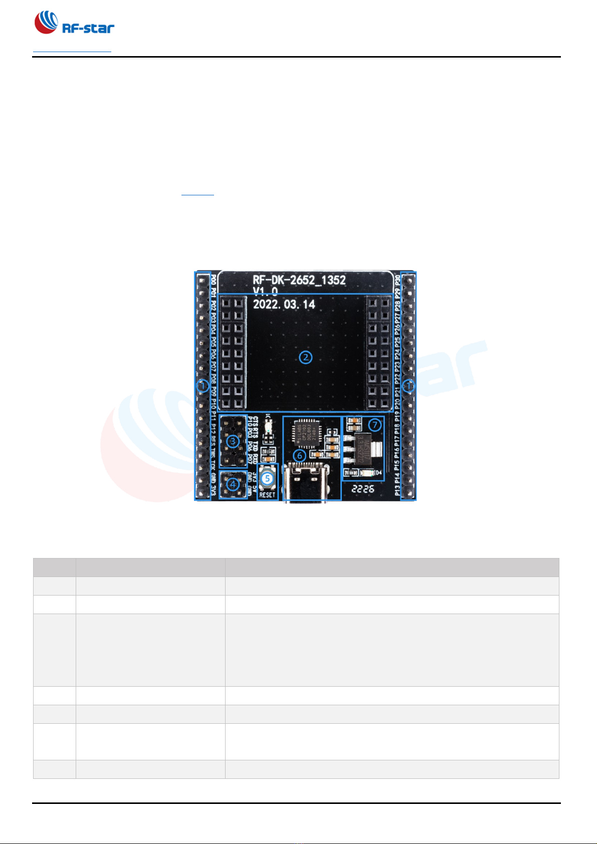
1 Description ........................................................................................................................................................................ 3
1.1 Development Kit Function and Resources .............................................................................................. 3
1.2 Supporting Modules.......................................................................................................................................... 4
1.3 Supporting Modules.......................................................................................................................................... 4
1.4 Schematic Diagram of RF-DK-2652_1352............................................................................................. 6
2 Pinboard Description..................................................................................................................................................... 7
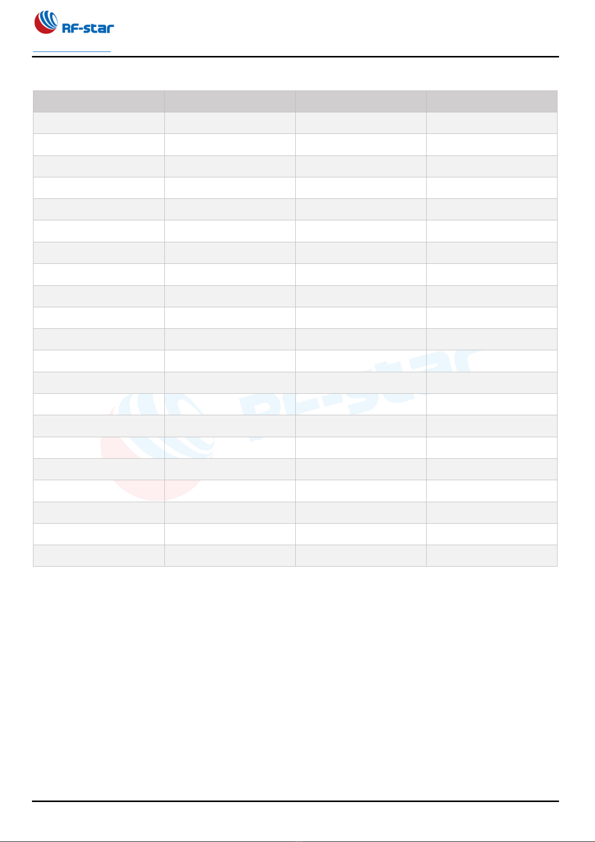
2.1 RF-TB-2652B1.................................................................................................................................................... 7
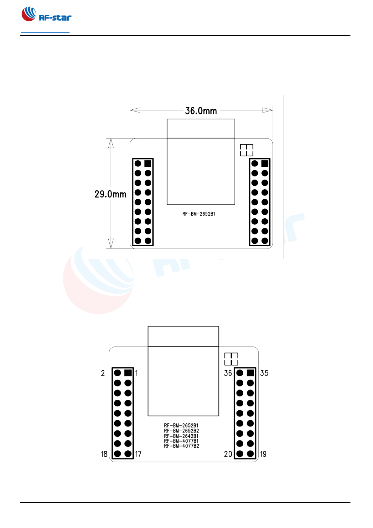
2.2 RF-TB-2652P1.................................................................................................................................................... 9
2.3 RF-TB-2652P3..................................................................................................................................................10
3 Quick Reference ...........................................................................................................................................................12
3.1 Preparation of Hardware and Software...................................................................................................12
3.2 Transparent Transmission Test by APP (iOS) ......................................................................................14
3.3 Transparent Transmission Test by APP (Android) ..............................................................................19
4 Trouble Shooting...........................................................................................................................................................24
4.1 Unsatisfactory Transmission Distance ....................................................................................................24
4.2 Vulnerable Module...........................................................................................................................................24
4.3 High Bit Error Rate ..........................................................................................................................................24
5 Revision History ............................................................................................................................................................25
6 Contact Us.......................................................................................................................................................................25
Table of Tables
Table 1. Function Region Description................................................................................................................ 3
Table 2. Table of Supporting Modules ............................................................................................................... 4
Table 3. Pin Functions of RF-DK-2652_1352................................................................................................. 5
Table 4. Pin Functions of RF-TB-2652B1 ........................................................................................................ 8
Table 5. Pin Functions of RF-TB-2652P1 ........................................................................................................ 9
Table 6. Pin Functions of RF-TB-2652B1 ......................................................................................................10

RF-DK-2652_1352
www.szrfstar.com V1.0 - Nov., 2022
Shenzhen RF-star Technology Co., Ltd. Page 3 of 26
1 Description
RF-DK-2652_1352 development board is a full set of test products that integrates RF-star SMT CC26xxxx (CC2642R,
CC2652R, CC2652R7, CC2652P, and CC2652P7) and CC1352xx (CC1352R, CC1352P, and CC1352P7) modules and
USB-to-UART IC to support the tests and development. This board greatly reduces the difficulty of customers' testing
and development. This manual describes how to use the development board. For more information about our products,
please visit the official website of RF-star.
1.1 Development Kit Function and Resources
The function region distribution is shown in Figure 1, and the function region description is shown in Table 1.
Figure 1. Function Region Distribution
Table 1. Function Region Description
No.
Function Region
Description
①
Module extension region
Supporting modules are shown in table 2.
②
Pin output region
All pins are pulled out, which is convenient for test.
③
UART jumper region
All modules’ pins are default as follows: P10-CTS, P03-CTS, P06-RX,
and P07-TX. Those pins can be connected to CTS, RTS, TXD, and RXD
respectively by jumpers. If the other UART pins of the module need to be
connected, just remove the jumper and connect to the related pins.
④
Power supply region
Power supply: 3.3 V / 5 V.
⑤
Button function region
Reset by pushing buttons.
⑥
USB-to-UART region
USB-to-UART function. Can be used as the USB-to-TTL tool without the
module embedded.
⑦
Power supply switch region
Power supply witch from 5 V to 3.3 V.

RF-DK-2652_1352
www.szrfstar.com V1.0 - Nov., 2022
Shenzhen RF-star Technology Co., Ltd. Page 4 of 26
1.2 Supporting Modules
Table 2. Table of Supporting Modules
Pinboard
Module List
RF-TB-2652B1
RF-BM-4077B1/B2
RF-BM-2642B1
RF-BM-2652B1/B2
RF-TB-2652P1
RF-BM-2652P1
RF-BM-2652P2/P2I
RF-TI1352P1
RF-TB-2652P3
RF-BM-2652P3
RF-TB-1352B1
RF-TI1352B1
RF-TB-2652RB1
RF-BM-2652RB1
RF-TB-2652RB2
RF-BM-2652RB2
1.3 Supporting Modules
Figure 2. Pin Diagram of RF-DK-2652_1352

RF-DK-2652_1352
www.szrfstar.com V1.0 - Nov., 2022
Shenzhen RF-star Technology Co., Ltd. Page 5 of 26
Table 3. Pin Functions of RF-DK-2652_1352
RF-DK-2652_1352 Pin
Description
RF-DK-2652_1352 Pin
Description
P00
GPIO
P01
GPIO
P02
GPIO
P03
GPIO
P04
GPIO
P05
GPIO
P06
GPIO
P07
GPIO
P08
GPIO
P09
GPIO
P10
GPIO
P11
GPIO
P12
GPIO
RES
Reset, active low
TMS
JTAG_TMSC
TCK
JTAG_TCKC
GND
Ground
3V3
Power supply pin
P13
GPIO
P14
GPIO
P15
GPIO
P16
GPIO
P17
GPIO
P18
GPIO
P19
GPIO
P20
GPIO
P21
GPIO
P22
GPIO
P23
GPIO
P24
GPIO
P25
GPIO
P26
GPIO
P27
GPIO
P28
GPIO
P29
GPIO
P30
GPIO
CTS
CTS (CP2102)
RTS
RTS (CP2102)
TXD
TXD (CP2102)
RXD
RXD (CP2102)
5V
Power supply pin

RF-DK-2652_1352
www.szrfstar.com V1.0 - Nov., 2022
Shenzhen RF-star Technology Co., Ltd. Page 7 of 26
2 Pinboard Description
Dimension of the pinboard. All the pinboards have the same dimension.
Figure 4. Dimension of the Pinboard
2.1 RF-TB-2652B1
RF-TB-2652B1 is the pinboard of the modules RF-BM-4077B1/B2, RF-BM-2642B1 and RF-BM-2652B1.
Figure 5. Pinboard RF-TB-2652B1

RF-DK-2652_1352
www.szrfstar.com V1.0 - Nov., 2022
Shenzhen RF-star Technology Co., Ltd. Page 8 of 26
Table 4. Pin Functions of RF-TB-2652B1
No.
Pin Description
No.
Pin Description
1
P01
2
P00
3
P03
4
P02
5
P05
6
P04
7
P07
8
P06
9
P09
10
P08
11
P11
12
P10
13
RES
14
P12
15
TCK
16
TMS
17
3V3
18
GND
19
P13
20
P14
21
P15
22
P16
23
P17
24
P18
25
P19
26
P20
27
P21
28
P22
29
P23
30
P24
31
P25
32
P26
33
P27
34
P28
35
P29
36
P30

RF-DK-2652_1352
www.szrfstar.com V1.0 - Nov., 2022
Shenzhen RF-star Technology Co., Ltd. Page 9 of 26
2.2 RF-TB-2652P1
RF-TB-2652P1 is the pinboard of the modules RF-BM-2652P1, RF-BM-2652P2/P2I and RF-TI1352P1.
Figure 6. Pinboard RF-TB-2652P1
Table 5. Pin Functions of RF-TB-2652P1
No.
Pin Description
No.
Pin Description
1
NC
2
NC
3
NC
4
NC
5
P05(DIO5)
6
NC
7
P07(DIO7)
8
P06(DIO6)
9
P09(DIO9)
10
P08(DIO8)
11
P11(DIO11)
12
P10(DIO10)
13
RES
14
P12(DIO12)
15
TCK
16
TMS
17
3V3
18
GND
19
P13(DIO13)
20
P14(DIO14)
21
P15(DIO15)
22
P16(DIO16)
23
P17(DIO17)
24
P18(DIO18)
25
P19(DIO19)
26
P20(DIO20)
27
P21(DIO21)
28
P22(DIO22)

RF-DK-2652_1352
www.szrfstar.com V1.0 - Nov., 2022
Shenzhen RF-star Technology Co., Ltd. Page 10 of 26
29
P23(DIO23)
30
P24(DIO24)
31
P25(DIO25)
32
P26(DIO26)
33
P27(DIO27)
34
NC
35
NC
36
NC
2.3 RF-TB-2652P3
RF-TB-2652P3 is the pinboard of the modules RF-BM-2652P3.
Figure 7. Pinboard RF-TB-2652B1
Table 6. Pin Functions of RF-TB-2652B1
No.
Pin Description
No.
Pin Description
1
NC
2
NC
3
NC
4
NC
5
P05(DIO5)
6
NC
7
P07(DIO7)
8
P06(DIO6)
9
NC
10
NC
11
NC
12
NC
13
RES
14
NC
15
TCK
16
TMS
17
3V3
18
GND
19
NC
20
NC
21
NC
22
P16(DIO16)

RF-DK-2652_1352
www.szrfstar.com V1.0 - Nov., 2022
Shenzhen RF-star Technology Co., Ltd. Page 12 of 26
3 Quick Reference
3.1 Preparation of Hardware and Software
1. Prepare RF-DK-2652_1352 development board, USB-to-Type C wire, and any pinboard of the module.
2. Install USB-to-UART driver, the driver file is as follows:
Figure 8. Driver File
3. According to the type of computer operating system, click to install the corresponding program. Take 32-bit computer
operating system as an example, install the program shown in the following. (64-bit operating system installs the
program suffixed with * 64).
Figure 9. Program Installment
4. After installation, right-click on "Computer - Management - Device Manager - Port" to see if the driver has been
installed successfully. The successful installation is shown in Figure 4 (Repeat step 2 if it is shown as a yellow
exclamation mark).

RF-DK-2652_1352
www.szrfstar.com V1.0 - Nov., 2022
Shenzhen RF-star Technology Co., Ltd. Page 13 of 26
Figure 10. Successful Installation
5. Open the serial port tool software, this software will automatically identify the USB-to-UART tool driver. The software
configuration is shown in Figure 5. After the settings are correct, click to open the serial port. (Note: If you use our
transparent program, you need to set BRTS low to accept data.)
Figure 11. UART Assist

RF-DK-2652_1352
www.szrfstar.com V1.0 - Nov., 2022
Shenzhen RF-star Technology Co., Ltd. Page 14 of 26
Figure 12. Successful Application
3.2 Transparent Transmission Test by APP (iOS)
1. Search for nRF Connect in the APP store:
Figure 13. nRF Connect APP
2. Open nRF Connect and the cellphone Bluetooth, press “scan” to search surrounding devices. As shown in the
following figure, there will be a Bluetooth device list being broadcast nearby. After clicking on the BLE device you

RF-DK-2652_1352
www.szrfstar.com V1.0 - Nov., 2022
Shenzhen RF-star Technology Co., Ltd. Page 15 of 26
want to connect to, the connection process begins.
Figure 14. Bluetooth Device List
3. Successful connection of nRF Connect screen and the UART Assistant screen is shown as follows:
Figure 15. Successful Connection of nRF Connect Screen

RF-DK-2652_1352
www.szrfstar.com V1.0 - Nov., 2022
Shenzhen RF-star Technology Co., Ltd. Page 19 of 26
3.3 Transparent Transmission Test by APP (Android)
1. Install APP “nRF Connect”:
.
Figure 22. nRF Connect APP
2. Open nRF Connect and the cellphone Bluetooth, and press “scan” to search surrounding devices. As shown in the
following figure, there will be a Bluetooth device list being broadcast nearby. After clicking on the BLE device you
want to connect to, the connection process begins.
Figure 23. Bluetooth Device List

RF-DK-2652_1352
www.szrfstar.com V1.0 - Nov., 2022
Shenzhen RF-star Technology Co., Ltd. Page 20 of 26
3. Successful connection of nRF Connect screen and the UART Assistant screen are shown as follows:
Figure 24. Successful Connection of nRF Connect Screen
Figure 25. Successful Connection of UART Assistant Screen
Table of contents
Other RF-Star Motherboard manuals
Popular Motherboard manuals by other brands

EFA
EFA Viking 3 user manual

Texas Instruments
Texas Instruments TLIN1431EVM user guide

Texas Instruments
Texas Instruments WCSP-Packaged bq24272 user guide

Mediatek Labs
Mediatek Labs LinkIt Developer's guide

Microchip Technology
Microchip Technology EVB-LAN9254-DIGIO user guide

GIGA-BYTE TECHNOLOGY
GIGA-BYTE TECHNOLOGY X570S AORUS MASTER user manual