RFID 4000 Series User manual

INSTALLATION AND OPERATING
MANUAL
FOR
SIMPLEX SERIAL READER INTERFACE
MODEL 4000 Series
MODEL 4000E Series
SIMPLEX SERIAL READER WRITER INTERFACE
MODEL 5000 Series
MODEL 5000E Series
Version 05/08

2
TABLE OF CONTENTS
SECTION 1 - GENERAL INFORMATION PAGE
1.1 INTRODUCTION…………………………………………..3
1.2 DESCRIPTION……………………………………………..4
1.3 SPECIFICATIONS………………………………………….4
1.4 PRODUCT ACCESSORIES………………………………...5
SECTION 2 - INSTALLATION
2.1 INTRODUCTION…………………………………………..6
2.2 UNPACKING AND INSPECTION…………………………6
2.3 POWER REQUIREMENTS………………………………...6
2.4 ANTENNA/READ HEAD INSTALLATION..……………..8
2.5 MOUNTING CONSIDERATIONS…………………………8
2.6 EXTERNAL INTERFERENCE…………………………….8
2.7 SERIAL INTERFACE CONNECTIONS…………………...9
SECTION 3 - OPERATION
3.1 INTRODUCTION…………………………………………11
3.2 APPLICABLE DOCUMENTS…………………………….11
3.3 DATA PROTOCOL……………………………………….11
3.4 ISSUING COMMANDS TO THE READER……………..11
3.5 ISSUING COMMANDS…………………………………..12
3.6 RESPONSES FROM THE READER……………………..13
4.0 WARRANTY……………………………………………...14
LIST OF FIGURES AND TABLES
FIGURE 2-1 THE MODEL 4000………………………………………7
TABLE 2-1 I/O CONNECTIONS – J3………………………………..9
TABLE 2-2 PIN FUNCTIONS……………………………………….10
TABLE 2-3 BAUD RATE SELECTION….…………………………10

3
SECTION 1
GENERAL INFORMATION
1.1 INTRODUCTION
This manual provides information pertaining to the installation and operation of the Model 4000
and Model 5000 Series Reader/Interface or Model 4000E and Model 5000E (the E signifying
enclosure). Formally the Series consists of 4 models:
Model Number Part Number Voltage Memory
4000E-RO 800-0086-02 12 VDC
16
Character
4001E-RO 800-0085-02 24 VDC
16
Character
4002E-RO 800-0086-00 12 VDC
8
Character
4003E-RO 800-0085-00 24 VDC
8
Character
4004E-RO 800-0086-04 12 VDC
32
Character
4005E-RO 800-0085-04 24 VDC
32
Character
5000E-RW 800-0085-01
800-0085-07 24 VDC 8
Character
5001E-RW 800-0085-03 24 VDC
16
Character
5002E-RW 800-0085-05 24 VDC
32
Character
5003E-RW 800-0086-01 12 VDC
8
Character
5004E-RW 800-0086-03 12 VDC
16
Character
5005E-RW 800-0086-05 12 VDC
32
Character
Where RO designates Reader Only and RW designates Reader Writer.
For simplicities sake any time the Model “4000” or “5000” is mentioned throughout this manual,
assume all Models are being talked about unless specifically noted otherwise. As they stand
above, these Models represent a PCB packaged. The letter “E” indicates inclusion of an
enclosure with Antenna cable and power wiring. These products are also available as a PCB
only for packaging into OEM applications or your electrical box.

4
1.2 DESCRIPTION
The Model 4000 and 5000 provides a half-duplex asynchronous bit serial data stream that will
interface to equipment compatible with RS-232-C specifications. The Reader/Interface is
configured as Data Terminal Equipment (DTE). The Model 4000 Reader/Interface provides an
excitation signal to an external Antenna to electro-magnetically power a passive Tag, otherwise
known as a Transponder or Label. The response from the Tag is sensed, amplified, filtered and
demodulated by the Reader/Interface to determine the data stored in the Tag. The unit operates
with many differing Antenna styles available from RFID, Inc.
The Reader/Interface contains circuitry to process Tag information as contained in the RFID,
Inc. family of Tags. An error detection algorithm provides error free operation. All messages
are transmitted in printable ASCII characters.
The Model 4000 operates as both a transmitter and receiver of RF signals. The unit provides a
low frequency electromagnetic field at 148 KHz to activate an RFID, Inc. tag in the vicinity of
the Antenna/Read Head field. Once the Tag is energized, it modulates the field in accordance
with data contained in the Tag’s eeprom chip. Receiving a return signal of 37 KHz from the
Tag, the unit processes this information and relays it for use by a host computer, process
controller or display and storage device. In addition to all of the above, the Model 5000 has the
ability to send a re-programming message that updates or changes the Tag’s programmed data.
1.3 SPECIFICATIONS
Communication Protocol: Half-Duplex, DTE, RS-232-C
Signal Lines: TxD, RxD, CTS, RTS
Data Transfer Rate: 1200-19200 baud
Data Format: 8 bits, 1 stop bit, no parity
Processing Speed: 8 Character Models 23.4 ms @ 9600 baud
16 Character Models 46.7 ms @ 9600 baud
32 Character Models 93.4 ms @ 9600 baud
Error Rate: Less than 1 in 100,000,000,000,000 readings
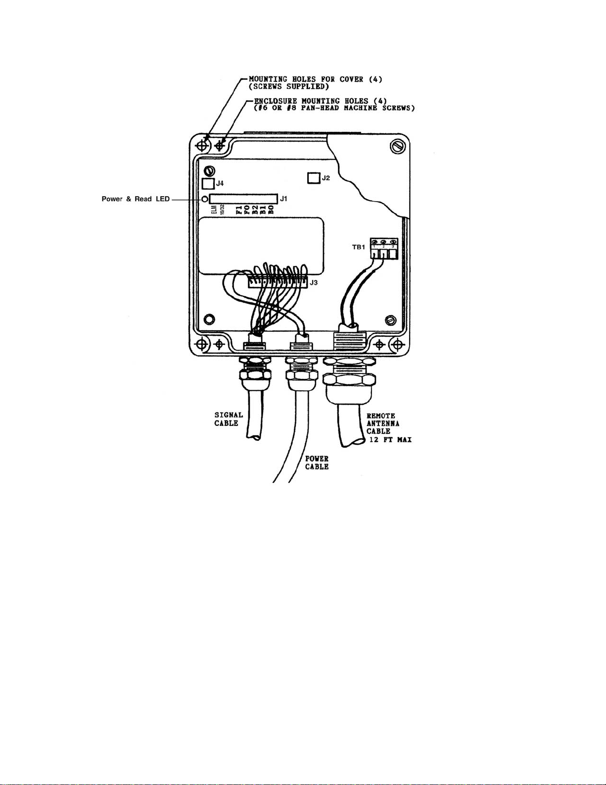
Connectors: Antenna: Angle entry terminal strip
Power and Data: 12 contact Locking header, 0.1” centers
Valid Read Output: 2 contact Locking header, 0.1” centers
Read Distance: Up to 36” (Tag and Antenna dependent)
Write Distance: Planar coil Tags, nearly 98% of read range
Ferrite coil Tags (Tag Model ending in an “M”) 60% of read range
Operating Frequency: 148 KHz (transmit) 37 KHz (receive)

5
Temperature Range:
Operating: -40 to +55 C
Non-Operating: -55 to +85 C
Power Supply Voltage: 12 VDC (8-14) or 24 VDC (18-32), Model dependent
Power Supply Current: 12 VDC Models: 250 mA (typ), 350 mA (max)
24 VDC Models: 400 mA (typ), 500 mA (max)
Dimensions: Enclosure: 4.8” L x 4.8” W x 2.2” H, clear lid
Weight: 2.6 lbs. (full system)
1.4 PRODUCT ACCESSORIES
Part Number Model/Description
720-0009-00 PS220 Power Supply, 12 VDC/500 mA
720-0008-00 PS230 Power Supply, 24 VDC/600 mA
719-0013-00 5100 Medium Prox Antenna
719-0013-01 5101 Small Prox Antenna
719-0015-00 5110 Hockey Puck Antenna
719-0016-00 5120 10.5” Tubular Antenna
730-0005-12 5100A1 Antenna Cable
102-0011-00 Insulated Wire w/o enclosure, 5.5” x 7.5”
719-0024-00 4’ x 2’ Extended Range Antenna
719-0026-00 Flat Pack Antenna, 7” x 7”
719-0027-00 Flat Pack Antenna, 12” x 12”
719-0025-00 Flat Pack Antenna, 21” x 17”
719-0086-00 Custom Slim Line Flexlink Conveyor Antenna
800-0050-00 Antenna Tuner

6
SECTION 2
INSTALLATION
2.1 INTRODUCTION
This section contains information for unpacking, installing and configuring the unit. Installation
includes power and signal wiring, as well as matching and connecting the Model 4000 or 5000 to
the Host Computer or Terminal. The unit is simple to use and install. It requires no alignment
or adjustments and needs no special precautions or other consideration. The Model 4000 may be
mounted in a variety of ways to suit the particular application and equipment. If, however, the
enclosure is mounted vertically, the preferable orientation would be with the glands down (note
Figure 2-2).
2.2 UNPACKING AND INSPECTION
If the shipping carton is damaged or shows evidence of abusive handling, inspect the Interface for
visible damage including dents, scratches, etc. If the unit appears damaged, contact the carrier and
RFID, Inc. Sales or Customer Service Departments immediately. Keep the shipping and packaging
material for the carrier's inspection. RFID, Inc. will arrange for repair or replacement of the
damaged unit without waiting for the claim settlement with the carrier.
2.3 POWER REQUIREMENTS
For Model 4000E or 5000E, power cabling is provided through the cable gland and pre-
connected at PCB address J3. For Model 4000, power connection must be accomplished by you
the user via purchasing of a connector fitting the pins at J3. I/O pin assignments are detailed in
Table 2-3.
The Reader/Interface must be powered from a regulated DC power source having the following
characteristics:
12 VDC Models: 250 mA (typ), 350 mA (max)
24 VDC Models: 400 mA (typ), 500 mA (max)
RFID, Inc. offers a full line of power supplies suited to optimize the Model 4000’s performance.
The maximum operation current has been calculated for worse case operation so further power
supply overrating is unnecessary. Additionally, the unit should be operated from a grounded
supply that has the same ground reference as the Host Computer.
WARNING
The power source should be turned off while making any connections to the unit. It is
recommended that the power source remain off anytime the circuit board is removed from
its enclosure assembly

7
FIGURE 2-1 ENCLOSURE MOUNTING DIAGRAM
J1 - In order from right to left
B0, B1, B2 = serial rate selection at B0 thru B2
F0, F1 = unused, will offer a serial format (RS-422-A) selection in next released versions
Blank = unused
16/32 = number of Tag characters selection, ON for 32, OFF for 16
ELM = Modem Eliminator, must be ON
J2 - Connection for heat dissipation to Resistor and Heat Sink
J3 - Serial I/O and Power, sequence is right to left, see section 2.7
J4 - Relay output
TB1 - Antenna Connector, 1& 2 are interchangeable, 3 is for a shield connection if used
LED – Solid light indicates power is on, blink indicates read has been achieved

8
2.4 ANTENNA/READ HEAD INSTALLATION
Connection for an external Antenna is provided at terminal block TB1 (angle entry terminal strip).
A cable is already attached when ordering the Model 4000E or 5000E.
The 12’ cable is custom and is part of the Antenna’s attenuated circuit, therefore altering the length
of the Antenna cable will affect read and write range between the Antenna and a Tag. It is
estimated that cutting the cable in half will shorten read range by 5% and cutting it down to 2’ will
shorten read range by 15%. A shorter cable can be accommodated without losing read range by
altering capacitance at the Model 4000 or 5000 PCB. Please ask us for such customization.
There is no polarity when inserting the wires into TB1, meaning either white or black wires can be
installed into either screw terminal. The maximum wire size accommodated by TB1 is 14 AWG.
2.5 MOUNTING CONSIDERATIONS
The Model 4000/5000’s Antenna operation and resulting read range can be affected by large metal
objects in close proximity. These objects distort the field area created by the Antenna as well as
absorb some of the energy it creates. The Model 5110 Antenna is specifically designed for metal
mounting. The following guidelines should be used in determining mounting locations:
1. Antenna is not significantly affected by small isolated metal objects, such as screws or
washers.
2. Large conductive areas such as metal plates, screens, etc., should be kept at least 3-3/4
inches from the Antenna.
3. The impact on Antenna operation is primarily a function of the area enclosed by the
conductor. That is, a closed loop of wire having the same area as the antenna base can have
nearly the same impact as a solid sheet of metal of the same area.
4. As a general rule of thumb, an Antenna may be spaced half its diameter from metal to
regain full functionality.
5. There is truly only one way to discover how an Antenna will function in a heavy metal
environment, install a system and test.
2.6 EXTERNAL INTERFERENCE
Since the Model 4000/5000 transmits and receives electromagnetic fields, it is susceptible to
interference from external sources of intentional and unintentional electromagnetic radiation. At its
frequency of operation, the effect of external sources falls off rapidly with distance. The operation
of the unit may be degraded by low level sources of interference within 10 feet or so of the unit,
and higher level sources up to 100 feet away. The following items should be given consideration
when operating the Reader:

9
1. Unshielded CRT's should be kept at least 10 feet from the antenna to reduce the effect of
the deflection yoke magnetic field.
2. Power input lines should be well filtered and free of switching spikes caused by thyristors,
SCR's, etc., which create interference across a broad spectrum of frequencies.
2.7 SERIAL INTERFACE CONNECTIONS
The Model 4000/5000 provides Tag data output in either a serial RS-232-C output. The protocol
for both is identified in Section 3.3 and the selection formats are listed below. The serial data
transfer (baud) rate is 1200 to 19200. Signal connections for the Interface are provided at PCB
address J3.
I/O CONNECTIONS - J3
RS232
COLOR
PIN FUNCTION
1 unused
2 unused
3 unused
4 unused
GRN 5CTS
YEL 6RTS
BLK 7TxD
RED 8RxD
9 unused
WHT 10 GROUND
11VDC
12 GROUND
Sequence for J3 is from right to left whereby the farthest right pin is #1
TABLE 2-1

10
PIN FUNCTIONS
SIGNAL NAME DIRECTION
RxD - Received Data To Reader
TxD - Transmitted Data From Reader
RTS - Request To Send From Reader
CTS - Clear To Send To Reader
If you are using a standard serial connector or have had one included with the delivery of your
system, the following pin-outs apply:
SIGNAL NAME PIN NO. DIRECTION
TxD 2 FromReader
RxD 3 ToReader
GND 5
RTS 6 FromReader
CTS 7 ToReader
Note: For part number 800-0085-07 the pin out is the same as above with the addition of pin 1 also
being a ground connection.
TABLE 2-2
BAUD RATE SELECTION
RATEB0 B1 B2
1200 ON ON ON
2400 OFF ON ON
4800 ON OFF ON
9600 OFF OFF ON
19.2 ON ON OFF
TABLE 2-3
The serial data transfer (baud) rate into or out of the unit is determined by the presence or absence
of shorting shunts on J1, shunts B0, B1, B2, at power up or reset.

11
SECTION 3
OPERATION
3.1 INTRODUCTION
This section pertains to the operating information of the Model 4000/5000. It describes the data
protocol, messages into and out of the unit, Antenna operating characteristics and other features of
the unit's Tag reading capability.
3.2 APPLICABLE DOCUMENTS
EIA Standard RS-232-C August, 1969
RFID, Inc. Interface Specification 719-0059-021 or 719-0060-021
3.3 DATA PROTOCOL
The data protocol utilizes ASCII characters for all data from the Model 4000/5000 and all control
functions from the host computer. Each message includes delimiters at the start and end of
message. Delimiters used for messages from the Model 4000/5000 are Line Feed (<LF>) at the
start of message and Carriage Return (<CR>) at the end of the message. For Commands into the
Model 4000/5000, the start of message delimiter may be either Line Feed (<LF>) or a left hand
bracket [ and the end of message delimiter may be either Carriage Return (<CR>) or a right hand
bracket ].
This protocol allows the Model 4000/5000 to be connected to a variety of computer systems,
printers and terminals. Since special ASCII control characters are avoided, software in the host
computer can be written in higher level languages without the need for special device driver
routines.
To command the unit, always use capital letters.
To test if installation is proper and complete, the words "RFID, Inc. Vx.x” will appear as the output
response of the Model 4000/5000 at power up. Reception of this message by the host indicates at
least one-way communication is functioning. To test communication from the host to the Model
4000, issue a Carriage Return (<CR>) and see if the Reader/Interface respond with a question mark
(?).
Messages into the Model 4000/5000 are checked for validity in the following manner. Upon
receipt of the start of message delimiter, any previously received and unprocessed message text is
discarded and the message search is reinitialized. Upon receipt of the end of message delimiter,
message characters received since the last start delimiter are processed, checked for validity and
acted upon.
3.4 THE READER’S BUFFERED MEMORY

12
Before proceeding, it is important to understand how the Reader’s memory functions. The Buffer
will store and hold only 1 Tag read, the last read. Presenting a Tag to the Reader will fill the Buffer
and the Reader will not re-report that Tag as long as it remains to be presented to the Reader. In
actuality, the Tags continue to be read by the Reader, compared to the info in the Buffer, and if
they equal the Tag will not be reported out the serial port a 2nd time. Removing the Tag from the
Reader will result in a watchdog timer commencing and upon reaching a preset timeout of 2.5
seconds the Buffer will be cleared. Then the original Tag can be presented again and read a 2nd
time.
Using the Buffer Reset, Initiate Self Test, and System Reset commands discussed below will also
clear the Buffer and allow a Tag to be read a 2nd time without it having to leave the Reader’s RF
field.
3.5 ISSUING COMMANDS TO THE MODEL 4000/5000
All commands and data must be done in CAPS. All commands are preceded by an open square
bracket, and ended by a closed square bracket or a carriage return. The Reader responds to the
following commands:
B Buffer reset
D Continuous Read Mode I Initiate Self Test
R Repeat Message
S System Reset or discontinue continuous Read Mode/return to single Read Mode
In addition to the above commands, the Model 5000 offers the additional following commands:
[Wxxxxxxxx] Write command for an 8 digit Tag
[Wxxxxxxxxxxxxxxxx] Write command for a 16 character Tag
[Wxxxxxxxxxxxxxxxxxxxxxxxxxxxxxxxx] Write command for a 32 character Tag
where x equals a capital ASCII character or number.
When sending a command to the unit, host operation assumes connection to a dumb terminal or a
PC in terminal emulation mode. For a clean, noise free background, using a DOS based program
like Procomm is preferable and recommended.
SYSTEM RESET
Type this: [S]
The Model 4000/5000 completely reinitializes and clears all buffers. Upon recognition of
this command, the unit will issue a response of "OK". Use this command to return to the
Single Report Mode if the Continuous Report Mode [D] has been entered.
BUFFER RESET
Type this: [B]
This command clears the Reader’s memory buffer, enabling it to report the same Tag twice.
Upon recognition of this command, the unit will issue an "ACKNOWLEDGE" response of
"OK".

2
REPORT DUPLICATE LABEL
Type this: [D]
This command enters the Reader into a Repeating Report mode. As long as a Tag is
presented to the Reader, it will repeatedly be read and reported out the serial port, to the
Read LED, and to the relay output. Upon recognition of this command, the unit will issue
an "ACKNOWLEDGE" response of "OK". You can only exit this mode by resetting with
[S] or by cycling power to the Reader.
INITIATE SELF TEST
Type this: [I]
This command initiates and internal self test, checking its own operating functions. This is
much like cycling power except the power up message is not sent. A successful self test
results an “ACKNOWLDEGE” response of "OK".
REPEAT MESSAGE
Type this: [R]
The Model 4000/5000 repeats the previously transmitted message. Upon recognition of
this command, the unit will issue one of two “ACKNOWLEDGE” responses. If the Reader
Buffer is empty, Tag data of all zeros will be reported. If the Reader Buffer holds Tag data,
that data will be reported.
3.6 RESPONSES RECEIVED FROM THE MODEL 4000/5000
TAG DATA
16 & 32 character Models read Tags programmed with an ASCII character format. Valid
character programmable digits are 0-9, A-Z in caps, and most normal keyboard characters.
8 character Models offer Tag digits of 0-9 ABCD only.
Tag data reports are as follows:
32 Character Readers
<LF>xxxxxxxxxxxxxxxxxxxxxxxxxxxxxxxx<CR>
16 Character Readers
<LF>xxxxxxxxxxxxxxxx<CR>
8 Character Readers
<LF>xxxxxxxx<CR>
Where LF (Line Feed) and CR (Carriage Return) are ASCII characters, and x equals data.
POWER UP MESSAGE
Displayed: RFID, Inc. Vx.x

If anything other than this appears, then an error has occurred or the Reader has not Self Tested
successfully.
ACKNOWLEDGE
Displayed: OK
Issued by the unit to indicate successful acceptance of a received command for those
commands that send no other acknowledgement of reception.
NEGATIVE ACKNOWLEDGE
Displayed: ?
Issued by the unit upon the receipt of an unrecognized command, improper delimiter
format, improper number of data characters for associated command, or illegal data
character value error.
4.0 WARRANTY
RFID, Inc. products are warranted against defects in materials and workmanship for one (1) year
from date of shipment. RFID, Inc. shall, at its option, either repair or replace products that prove to
be defective and are returned with freight prepaid to RFID, Inc.’s plant within the warranty period.
The foregoing warranty shall not apply to defects resulting from abuse, misuse, accident, alteration,
neglect or unauthorized repair or installation. RFID, Inc. shall have the right of final determination
as to the existence and cause of the defect.
THE WARRANTY SET FORTH ABOVE IS EXCLUSIVE AND NO OTHER WARRANTY,
WHETHER WRITTEN OR ORAL, IS EXPRESSED OR IMPLIED. RFID, Inc. SPECIFICALLY
DISCLAIMS THE IMPLIED WARRANTIES OR MERCHANTABILITY AND FITNESS FOR
A PARTICULAR PURPOSE.
The remedies provided herein are Buyer's sole and exclusive remedies. In no event shall RFID,
Inc. be liable for direct, indirect, special, incidental or consequential damages, (including loss of
profits) whether based on contract, tort, or any other legal theory.
This manual suits for next models
15
Table of contents
Other RFID Antenna manuals
Popular Antenna manuals by other brands

Bodet
Bodet 907 047 installation manual

BARKER & WILLIAMSON
BARKER & WILLIAMSON AT-110 manual

Altelix
Altelix AU5158G12 installation instructions

Agilent Technologies
Agilent Technologies 85309B LO manual

KVH Industries
KVH Industries TracPhone V30 Installation Addendum

Siemens
Siemens RUGGEDCOM ANT1995-4MM operating instructions