RFID 8075E User manual

Product Manual
Model 8075E PROFINET Series Interface
for LF 125 kHz and 148 kHz Smart Antennas
This document is made available to product owners and users for integration purposes. Proprietary and confidential
information is contained herein, therefore this document is protected by all applicable international intellectual property
laws. The information contained in this document is constantly subject to revision (see Rev. number at top of each page).

Revision 2/2021
14190 E. Jewell Avenue, Suite 4, Aurora CO 80012 - TEL: 303-366-1234 –Proudly Made in the USA
www.rfidinc.com
Model 8075E Operations Manual v7.21
2
Table of Contents
How to Contact Us .................................................................................................................................... 3
Part Numbers............................................................................................................................................. 3
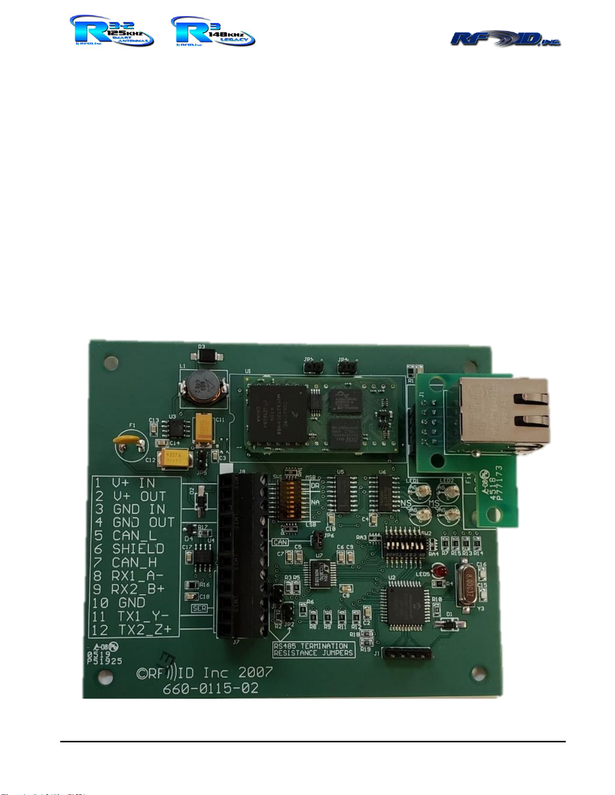
Hardware Description.............................................................................................................................. 4
Specifications........................................................................................................................................... 4
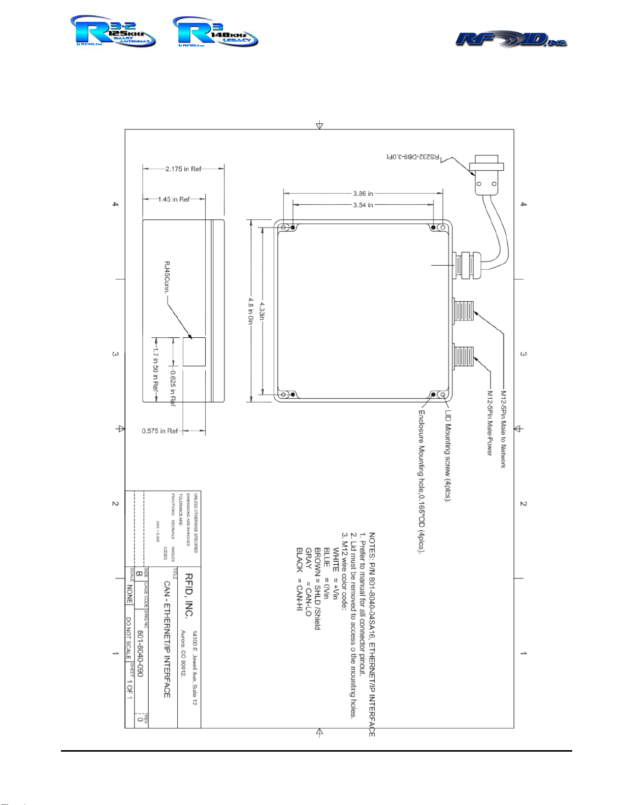
Drawing.................................................................................................................................................... 5
Pigtail Wire Specifications ...................................................................................................................... 6
Power Requirements................................................................................................................................ 6
Cabling the Reader –Power .................................................................................................................... 6
Wiring Color Codes................................................................................................................................. 6
M12 Pinouts............................................................................................................................................. 6
CAN Smart Antenna Readers and LF Passive RFID Tags ....................................................................... 7
Integer Data.............................................................................................................................................. 7
SW1 & SW2 Dipswitches......................................................................................................................... 7
RW/RO (read write or read only) ............................................................................................................ 8
Summary Default Settings....................................................................................................................... 8
Serial Port Settings................................................................................................................................... 9
Serial Port Commands to the Interface.................................................................................................... 10
Serial Port Commands to the Smart Antenna RFID Readers.................................................................. 12
Configuring PROFINET - LED Status Lights ........................................................................................ 13
Setting up PRFINET Interface ................................................................................................................ 14
Issuing Commands via PROFINET ........................................................................................................ 15
“I/O Command Bits 1 Byte”.................................................................................................................... 15
Example Module setups Integer Mode Smart Antenna Readers ........................................................... 17
Example Module setups ASCII Mode Smart Antenna Readers.............................................................. 21
Example Module setups Integer Mode Serial Smart Antenna Reader.................................................... 29
Example Module setups ASCII Mode Serial Readers ............................................................................ 33
Smart Antenna Reader Addressing ......................................................................................................... 41
Warranty.................................................................................................................................................. 42

Revision 2/2021
14190 E. Jewell Avenue, Suite 4, Aurora CO 80012 - TEL: 303-366-1234 –Proudly Made in the USA
www.rfidinc.com
Model 8075E Operations Manual v7.21
3
How to Contact Us
303-366-1234 x101
Tech Support: 303-910-5447 cell 9am to 6pm PST
Sales: 719-330-2349 cell 7am to 5pm CST
Part Numbers
Model
Number
Part Number
Description
8075E-
04SA08
801-8075-
04SA08
Model 8075E-04SA08 PROFINET Interface, CAN Smart Antennas, M12
connector, 24vdc, 8 characters
8075E-
14SA08
801-8075-
14SA08
Model 8075E-14SA08 PROFINET Interface, CAN Smart Antennas, pigtail
wiring, 24vdc, 8 characters
8075E-
24SA08
801-8075-
24SA08
Model 8075E-24SA08 PROFINET Interface, CAN Smart Antennas, dual
pigtail wiring, 24vdc, 8 characters
8075E-
04SA16
801-8075-
04SA16
Model 8075E-04SA16 PROFINET Interface, CAN Smart Antennas, M12
connector, 24vdc, 16 characters
8075E-
14SA16
801-8075-
14SA16
Model 8075E-14SA16 PROFINET Interface, CAN Smart Antennas, pigtail
wiring, 24vdc, 16 characters
8075E-
24SA16
801-8075-
24SA16
Model 8075E-24SA16 PROFINET Interface, CAN Smart Antennas, dual
pigtail wiring, 24vdc, 16 characters

Revision 2/2021
14190 E. Jewell Avenue, Suite 4, Aurora CO 80012 - TEL: 303-366-1234 –Proudly Made in the USA
www.rfidinc.com
Model 8075E Operations Manual v7.21
4
Hardware Description
This Interface is the master in managing a network of up to 32 networkable CAN based RFID Readers
termed Smart Antennas (or as an PROFINET bridge from our series of serial Reader Models 4000E,
5000E, and 7000E), and ultimately presents RFID Tag data from the networked Smart Antennas in
PROFINET format. Any sections of this manual pertaining to settings or functions with serial RFID
Readers have the word serial highlighted in yellow to alert users of the CAN based Smart Antennas those
sections can be skipped or ignored. Dual pigtail wiring would be used if the Interface is to be located in
the center of the trunk network line of Smart Antenna RFID Readers thus providing a connection in either
direction or an M12 T-Connector can be used to split the single on board M12 connector into two
directions.
Specifications
Physical:
Dimensions (w/o
connectors):
4.8" square x 2.175"
122mm square x 55mm
Weight (w/o cable):
11 oz.
312 grams
Connector Options:
CAN Port(s): M12 or
pigtails
Power: M12, Quick Connect
power jack or pigtails
RS232 Port: 9pin D-sub or
pigtails
PROFINET: RJ45
Electrical:
Input:
+9VDC –+28VDC
Draw:
125mA min –200mA max
150mA typical
Materials:
Housing, Base:
Polycarbonate, opaque
NEMA 4X
Lid:
Polycarbonate, clear
LED:
On = power
Blink = read achieved
Environment:
Storage
Temperature:
-40°F to 185°F
-40°C to +85°C
Operating
Temperature:
-40°F to +131°F
-40°C to +55°C
Certs:
IP-50
RoHS & CE & REACH

Revision 2/2021
14190 E. Jewell Avenue, Suite 4, Aurora CO 80012 - TEL: 303-366-1234 –Proudly Made in the USA
www.rfidinc.com
Model 8075E Operations Manual v7.21
5
Drawing PROFINET Interface w/M12 Connectors Drawing Shown

Revision 2/2021
14190 E. Jewell Avenue, Suite 4, Aurora CO 80012 - TEL: 303-366-1234 –Proudly Made in the USA
www.rfidinc.com
Model 8075E Operations Manual v7.21
6
Pigtail Wire Specifications
Shielded (22 AWG for cable length up to 25’ and 16 AWG for communication lengths beyond 25’)
insulated, stranded wire is recommended. All wires should be stripped approximately 3/8 inches and
tinned.
Power Requirements
The Interface can be powered from regulated, linear, or switching power sources having the
characteristics defined in the Specifications section of this document (9 to 28 volts). The Interface
should be operated from a grounded supply that has the same ground reference as the host computer or
logic device.
Cabling the Reader –Power
The Interface is delivered with two power connection options, an M12 connection or connection to bare
pigtail wiring.
Wiring Color Codes
CAN WIRE COLOR
SIGNAL NAME
RED
+9 to +28VDC Input Unfused
BLACK
DC Ground (-)
WHITE
CAN-HI
BLUE
CAN-LO
BARE/DRAIN
EARTH GROUND, DRAIN, SHIELD
RS232 WIRE COLOR
SIGNAL NAME
BLACK
Tx
RED
Rx
WHITE
Ground
M12 Pinouts

Revision 2/2021
14190 E. Jewell Avenue, Suite 4, Aurora CO 80012 - TEL: 303-366-1234 –Proudly Made in the USA
www.rfidinc.com
Model 8075E Operations Manual v7.21
7
CAN Smart Antenna Readers and LF Passive RFID Tags
Smart Antenna RFID Readers are addressable and simply provide a means of emitting the RF signal to
energize a Tag, receive data back from a Tag and pass Tag data back to the Interface. Smart Antennas
can also program RFID Tags. RFID Tags store 8 or 16 ASCII characters (limited to capital letters,
numbers and some symbols). Smart Antenna Readers operate at +9VDC to +28VDC consuming 160mA
max.
Integer Data
Although the Smart Antenna RFID Readers and Tags use 8 or 16 character formats, the Model 8075E
Interface can convert DINT data from the PROFINET scanner to 8/16 character numerical strings and
convert the string from the Tag into a DINT before sending to the PROFINET bus.
SW1 & SW2 Dipswitches
The SW1 switch block is inactive. SW2 is located at right center shown below used to configure ASCII
or Integer data, serial type, and serial baud rate.

Revision 2/2021
14190 E. Jewell Avenue, Suite 4, Aurora CO 80012 - TEL: 303-366-1234 –Proudly Made in the USA
www.rfidinc.com
Model 8075E Operations Manual v7.21
8
RW/RO (read write or read only)
All Smart Antenna Readers are RW. When the Interface is configured for RO however, you are simply
removing Tag data from the scanner output. Use the SW2 dipswitch settings of the first 4 rows below
for networkable CAN Smart Antenna Readers and the second 4 rows for serial Readers like the Models
4000E, 5000E, 7000E:
Summary Default Settings
RS232 - Full Duplex, 9600, 8, N, 1, Single Read Mode
PROFINET –CAN RW Integer, Dynamic IP Address, Single Tag Report Read Mode
*Defaults are noted with an asterisk in tables below*
Switch 1 (LSB)
Switch 2
Switch 3
Smart Antenna Data Type
OFF
ON
OFF
CAN ASCII RW
ON
ON
OFF
CAN INTEGER RW*
OFF
ON
ON
CAN ASCII RO
ON
ON
ON
CAN INTEGER RO
OFF
OFF
OFF
SERIAL ASCII RW
ON
OFF
OFF
SERIAL INTEGER RW
OFF
OFF
ON
SERIAL ASCII RO
ON
OFF
ON
SERIAL INTEGER RO
Table 1 - SW2 CAN Smart Antenna Interface Modes
The PROFINET Interface can only use even values. The extra byte of data must be ignored
Type
CMD
ADD
DATA
Total
Actual
CAN ASCII RW
1
2
16
19
20
CAN INTEGER RW*
1
1
4
6
6
CAN ASCII RO
1
2
16
19
20
CAN INTEGER RO
1
1
4
6
6
Table 2 - CAN Smart Antenna PROFINET data sizes

Revision 2/2021
14190 E. Jewell Avenue, Suite 4, Aurora CO 80012 - TEL: 303-366-1234 –Proudly Made in the USA
www.rfidinc.com
Model 8075E Operations Manual v7.21
9
Serial Port Settings
Switch 4
Switch 5
Switch 6
Serial Baud Rate
OFF
OFF
OFF
1200
ON
OFF
OFF
2400
OFF
ON
OFF
4800
ON
ON
OFF
9600*
OFF
OFF
ON
19200
ON
OFF
ON
38400
OFF
ON
ON
Do not use
ON
ON
ON
Do not use
Table 3 - SW2 & Baud Rate Selection
*9600, 8, 1, N
RS232 full duplex, RS422 full duplex (5 wire), RS422 half-duplex (3 wire)
Switch 7
Switch 8
Serial hardware type
OFF
OFF
RS232 full duplex*
ON
OFF
RS422 half-duplex
OFF
ON
RS422 full duplex
Table 4 - SW2 Serial Port Hardware Select
The PROFINET Interface can only use even values. The extra byte of data must be ignored.
TYPE
CMD
DATA
Total
Actual
SERIAL ASCII RW
1
16
17
18
SERIAL INTEGER RW
1
4
5
6
SERIAL ASCII RO
1
16
17
18
SERIAL INTEGER RW
1
4
5
6
Table 5 –Serial Port PROFINET Data Sizes
Start & End Characters for Serial to PROFINET Bridge Mode
This section pertains only to use of the Interface when linked with serial Readers, NOT the networkable
CAN Smart Antenna Readers. The serial port software frames Tag data from the Smart Antenna RFID
Readers based on its End and Start character settings. Start may be set to zero in which case any character
is accepted as a start character. End must be set to a value other than zero to delimit incoming tag data.
The default settings are:
Start = 0x00
End = 0x0D (Carriage return)

Revision 2/2021
14190 E. Jewell Avenue, Suite 4, Aurora CO 80012 - TEL: 303-366-1234 –Proudly Made in the USA
www.rfidinc.com
Model 8075E Operations Manual v7.21
10
Serial Port Commands to the Interface
The characters of open square bracket and closed square bracket are used to frame an incoming command
message. When the serial port software receives the open square bracket [ character it expects the rest of
the message to be a command and the last character to be a closed square bracket ].
[1CXX]
Format: 1 = Start and End Char setting, C = Start or End character, XX = hex value
Valid values: C = ‘S’ or ‘E’, XX = a hex value. Values outside of ASCII letters and numbers are
recommended
Response: OK
Example 1: [1S0A] sets the start character as a Line Feed
Example 2: [1E0D] sets the end character as a Carriage Return
Example 3: [1S00] sets the start character to none
[2NNOO] –Change Reader Address
Format: 2 = Set Reader CAN address, NN = New CAN address, OO = Current (old) CAN address
Valid Addresses: 01 to 32
Response: OK, FAILED1, or FAILED2
Example: [23001] change Reader from address #01 to address #30
Example response 1: OK = #01 existed on the CAN bus and has been reset to #30
Example response 2: FAILED1 = #01 does not exist on the bus
Example response 3: FAILED2 = #30 is already in use
[3]
Format: 3 = Scan for present Readers
Response: RDR1, RDR2, RDRn…
Example: [3] Request a scan of present Readers
Example response 01 07 19 31
[4=IP address]
There are options for either a static IP address or a dynamic IP address. Interfaces are shipped with
dynamic IP address as the default. The following command is for a static IP address:
Format: 4=NNN.NNN.NNN.NNN
Response: OK
Example: [4=10.0.1.42] Set new IP address
To return to a dynamic IP address, issue the command [4=0.0.0.0]
[5=Mask]
Format: 5=NNN.NNN.NNN.NNN

Revision 2/2021
14190 E. Jewell Avenue, Suite 4, Aurora CO 80012 - TEL: 303-366-1234 –Proudly Made in the USA
www.rfidinc.com
Model 8075E Operations Manual v7.21
11
Response: OK
Example: [5=255.255.255.0] Set new subnet mask
[6=Gateway]
Format: 6=NNN.NNN.NNN.NNN
Response: OK
Example: [6=10.0.1.1] Set new gateway
[7]
Format: 7 = Get IP settings
Response:
IP=10.0.1.42
Mask=255.255.255.0
Gateway=10.0.1.1
Example: [7] Request IP settings
[S] (default operating mode)
This command changes the data output mode to SINGLE on the PROFINET connection, meaning a
Tag will be read and reported one time.
Format: S = Single Mode
Response: OK
Example: [S]
[SC]
This command changes the data output mode to SINGLE on the Serial connection.
Format: SC = Single Mode
Response: OK
Example: [SC]
[P]
This command changes the data output mode to POLLING on the PROFINET connection. Use [TAA]
command below to poll.
Format: P = Polling Mode
Response: OK
Example: [P]
[PC]
This command changes the data output mode to POLLING on the Serial connection. Use [TAA]
command below to poll.
Format: PC = Polling Mode
Response: OK
Example: [PC]

Revision 2/2021
14190 E. Jewell Avenue, Suite 4, Aurora CO 80012 - TEL: 303-366-1234 –Proudly Made in the USA
www.rfidinc.com
Model 8075E Operations Manual v7.21
12
Serial Port Commands to the Smart Antenna RFID Readers
[MAAXX]
This command changes the write mode of the addressed Smart Antenna Reader. There are different
types of RFID Tags with differing types of coils and tuning. The values discussed below place a Smart
Antenna Reader into the writing mode appropriate to the RFID Tags in your possession. Default mode
is 18, used for all planar coil based Tags. Mode 08 is used for all ferrite coil based RFID Tags.
Contact us if you are unsure or having difficulty in writing Tags.
Format: M = mode command, AA = CAN address, XX = value
Valid values: 00, 08, 10, 18
Response: If successful OK, if not ERROR
Example: [M1218] Establish new WRITE MODE value to Smart Antenna Reader #12
Example response: 12 OK, 12 = Reader #, OK = successful EEPROM change
[VAA]
This command reads the addressed Reader’s write mode
Format: AA = CAN address, V = view
Response: The value of addressed Reader write mode
Example: [V07] Read WRITE MODE value of Reader #07
Example response: 07 18, 07 = reader #, 18 = WRITE MODE
[TAA]
This command erases the Readers’Tag buffer causing it to read the tag again if one is present. If the
Reader does not respond within 400mS, the master ends the command by sending a lower case e. If a
Tag is present to the Reader then the master outputs the Tag data normally
Format: AA = CAN address, T = poll
Response: e = no tag in range, or Tag data = Tag present to Reader
[IAA]
This command reads the firmware version of the addressed Reader
Format: AA = CAN address, I = Firmware Version
Response: The current Firmware version AA.v.x.xx
Response format: AA = Reader address, v.x.xx = Firmware Version
Example: [I22] Read the Firmware Version of Reader #22
Example response: 22.v.1.12, 22 = Reader #, v.1.12 = firmware version
[WAADATA]
Writes 8 or 16 characters of data for tag on addressed Reader
Format: W = Write command, AA = CAN address, DATA = 8 or 16 ASCII characters
Response: PROGRAMMED if successful, FAILED if not successful
Example: [W015555555533333333] Write 5555555533333333 to tag on Reader 1
Example response successful: PROGRAMMED
Example response if failure: NO RESPONSE

Revision 2/2021
14190 E. Jewell Avenue, Suite 4, Aurora CO 80012 - TEL: 303-366-1234 –Proudly Made in the USA
www.rfidinc.com
Model 8075E Operations Manual v7.21
13
Configuring PROFINET - LED Status Lights
There are 4 status LED’s. There are some typos on the silk LED labels on the PCB of versions 0115-01
and 0115-02 Interface PCB’s. LED1 is actually NS, LED2 is actually MS, NS is actually Data Rate,
and MS is actually Link Activity. Below are detailed explanations of each.
LED1 Network Status
•Off = No power or no IP address
•Green = Ethernet IP connection established
•Green Flashing = No Ethernet IP connection established
•Red = Duplicate IP address detected
•Red Flashing = Ethernet IP connection timed out
•Alternating Red/Green = Self-test in progress
LED2 Module Status
•Off = No power
•Green = Ethernet IP connection established
•Green Flashing = No Ethernet IP connection established
•Red = Mayor Fault (unrecoverable)
•Red Flashing = Minor Fault (recoverable)
•Alternating Red/Green = Self-test in progress
NS = Data Rate
•Off = 10 Mbps
•Green = 100 Mbps
•Alternating Red/Green = Self-test in progress

Revision 2/2021
14190 E. Jewell Avenue, Suite 4, Aurora CO 80012 - TEL: 303-366-1234 –Proudly Made in the USA
www.rfidinc.com
Model 8075E Operations Manual v7.21
14
MS = Link Activity
•Off = No power
•Green = Connected to Ethernet network
•Green Flashing = RX/TX Activity
•Alternating Red/Green = Self-test in progress
Setting up PRFINET Interface
You need a GSDML XML file.

Revision 2/2021
14190 E. Jewell Avenue, Suite 4, Aurora CO 80012 - TEL: 303-366-1234 –Proudly Made in the USA
www.rfidinc.com
Model 8075E Operations Manual v7.21
15
Issuing Commands via PROFINET
Writing Tags via PROFINET is not available but may be done so via the serial port.
“I/O Command Bits 1 Byte”
Description
This Byte should be the first one on any setup. It is via this byte that commands are sent from the
PROFINET scanner to the Smart antennas. The In Byte contains error bits to indicate command
failure types. Data type bits are also represented. They indicate if ASCII or Integer mode in in use.
Command Byte Out (from scanner):
Byte
BIT 7
BIT 6
BIT 5
BIT 4
BIT 3
BIT 2
BIT 1
BIT 0
CMD
Not Used, Write with Zeros
Command code bits
Out Toggle
Command Byte In (to scanner):
Byte
BIT 7
BIT 6
BIT 5
BIT 4
BIT 3
BIT 2
BIT 1
BIT 0
CMD
Data Type Bits
ERROR Bits
Command code bits
In Toggle

Revision 2/2021
14190 E. Jewell Avenue, Suite 4, Aurora CO 80012 - TEL: 303-366-1234 –Proudly Made in the USA
www.rfidinc.com
Model 8075E Operations Manual v7.21
16
Out Toggle bit
Every time this bit is toggled, the slave will execute the command as per the command bits.
In Toggle bit
The salve toggles this bit every time it loads new values on to the field bus.
In Command Byte bit codes
WRITE_TAG
0
0
1
SINGLE_MODE
0
1
0
POLLING_MODE
0
1
1
TRANSFER_TAG
1
0
0
WRITE_MODE
1
0
1
VIEW_WRITE_MODE
1
1
0
Table 7 - Command Bits 1:3
Successful command
0
0
Bad read or write/Ins data not valid
0
1
No Response from read head
1
0
Invalid Command or Command Parameters
1
1
Table 8 - ERROR Bits 4:5
Smart Antenna ASCII
0
0
Smart Antenna INTEGER
0
1
Serial Reader ASCII
1
0
Serial Reader INTEGER
1
1
Table 9 - Data Type Bits 6:7

Revision 2/2021
14190 E. Jewell Avenue, Suite 4, Aurora CO 80012 - TEL: 303-366-1234 –Proudly Made in the USA
www.rfidinc.com
Model 8075E Operations Manual v7.21
17
Screenshot showing the reading of both the serial port and EIP port simultaneously.
Example Module setups Integer Mode Smart Antenna Readers
Write Tag Command, Smart Antenna Reader Integer Mode “Scanner Out”:
Byte
BIT 7
BIT 6
BIT 5
BIT 4
BIT 3
BIT 2
BIT 1
BIT 0
CMD
Not Used, Write With Zeros
0
0
1
Toggle
Address
Not Used
Smart Antenna Address
DATA 0
Data to Write, 32 Bit Integer
DATA 1
DATA 2
DATA 3
Response “Scanner In”:
Byte
BIT 7
BIT 6
BIT 5
BIT 4
BIT 3
BIT 2
BIT 1
BIT 0
CMD
Data Type Bits
ERROR Bits
0
0
1
Toggle
Address
Not Used
Smart Antenna Address
DATA 0
Written Data, 32 bit Integer
DATA 1
DATA 2
DATA 3
ERROR Bits:
00 = Successful, Data valid
01 = Failure, Data not valid
10 = No response from Read/Write Head

Revision 2/2021
14190 E. Jewell Avenue, Suite 4, Aurora CO 80012 - TEL: 303-366-1234 –Proudly Made in the USA
www.rfidinc.com
Model 8075E Operations Manual v7.21
18
Single Mode Command, Smart Antenna Reader Integer Mode “Scanner Out”:
Byte
BIT 7
BIT 6
BIT 5
BIT 4
BIT 3
BIT 2
BIT 1
BIT 0
CMD
Not Used, Write With Zeros
0
1
0
Toggle
Address
Not Used
Smart Antenna Address
DATA 0
Not Used, Write With Zeros
DATA 1
DATA 2
DATA 3
Response “Scanner In”:
Byte
BIT 7
BIT 6
BIT 5
BIT 4
BIT 3
BIT 2
BIT 1
BIT 0
CMD
Data Type Bits
ERROR Bits
0
1
0
Toggle
Address
Not Used
Smart Antenna Address
DATA 0
Not Used, Unmodified
DATA 1
DATA 2
DATA 3
ERROR Bits:
00 = Successful Command
10 = No Response from Read/Write Head
Polling Mode Command, Smart Reader Antenna Integer Mode “Scanner Out”:
Byte
BIT 7
BIT 6
BIT 5
BIT 4
BIT 3
BIT 2
BIT 1
BIT 0
CMD
Not Used, Write With Zeros
0
1
1
Toggle
Address
Not Used
Smart Antenna Address
DATA 0
Not Used, Write With Zeros
DATA 1
DATA 2
DATA 3

Revision 2/2021
14190 E. Jewell Avenue, Suite 4, Aurora CO 80012 - TEL: 303-366-1234 –Proudly Made in the USA
www.rfidinc.com
Model 8075E Operations Manual v7.21
19
Response “Scanner In”:
Byte
BIT 7
BIT 6
BIT 5
BIT 4
BIT 3
BIT 2
BIT 1
BIT 0
CMD
Data Type Bits
ERROR Bits
0
1
1
Toggle
Address
Not Used
Smart Antenna Address
DATA 0
Not Used, Unmodified
DATA 1
DATA 2
DATA 3
ERROR Bits:
00 = Successful Command
10 = No response from Read Write Head
Transfer Command for Polling Mode, Smart Reader Antenna Integer Mode “Scanner Out”:
Byte
BIT 7
BIT 6
BIT 5
BIT 4
BIT 3
BIT 2
BIT 1
BIT 0
CMD
Not Used, Write With Zeros
1
0
0
Toggle
Address
Not Used
Smart Antenna Address
DATA 0
Not Used, Write With Zeros
DATA 1
DATA 2
DATA 3
Response “Scanner In”:
Byte
BIT 7
BIT 6
BIT 5
BIT 4
BIT 3
BIT 2
BIT 1
BIT 0
CMD
Data Type Bits
ERROR Bits
1
0
0
Toggle
Address
Not Used
Smart Antenna Address
DATA 0
Data Read, 32 Bit Integer
DATA 1
DATA 2
DATA 3
ERROR Bits:
00 = Successful, New Data
01 = Successful, No New Data
10 = No Response from Read/Write Head

Revision 2/2021
14190 E. Jewell Avenue, Suite 4, Aurora CO 80012 - TEL: 303-366-1234 –Proudly Made in the USA
www.rfidinc.com
Model 8075E Operations Manual v7.21
20
Write Mode Command, Smart Antenna Reader Integer Mode “Scanner Out”:
Byte
BIT 7
BIT 6
BIT 5
BIT 4
BIT 3
BIT 2
BIT 1
BIT 0
CMD
Not Used, Write With Zeros
1
0
1
Toggle
Address
Not Used
Smart Antenna Address
DATA 0
Not Used
New Write Mode Value
DATA 1
Not Used, Write With Zeros
DATA 2
DATA 3
Response “Scanner In”:
Byte
BIT 7
BIT 6
BIT 5
BIT 4
BIT 3
BIT 2
BIT 1
BIT 0
CMD
Data Type Bits
ERROR Bits
1
0
1
Toggle
Address
Not Used
Smart Antenna Address
DATA 0
Not Used, Unmodified
New Write Mode Value
DATA 1
Not Used, Unmodified
DATA 2
DATA 3
ERROR Bits:
00 = Successful Command, New Write Mode Set
01 = Failure to Set new Write Mode
10 = No Response from Read/Write Head
View Write Mode Command, Smart Antenna Reader Integer Mode “Scanner Out”:
Byte
BIT 7
BIT 6
BIT 5
BIT 4
BIT 3
BIT 2
BIT 1
BIT 0
CMD
Not used, Write with Zeros
1
1
0
Toggle
Address
Not used
Smart Antenna Address
DATA 0
Not Used, Write With Zeros
DATA 1
DATA 2
DATA 3
Table of contents
Other RFID Antenna manuals
Popular Antenna manuals by other brands

Maxview
Maxview COMBO/50 Installation & user's instructions

Intellian
Intellian v80G Installation and operation user guide

JMA
JMA SX Series Guide

Tarheel Antennas
Tarheel Antennas Little Tarheel HP instruction manual

Ubiquiti
Ubiquiti AF-5G30-S45 quick start guide

Jensen
Jensen JAN139 installation instructions

Hubbell
Hubbell ATS-OP-245-6-4 Series manual

Diamond Antenna
Diamond Antenna CP6 Assembly instructions

Lutron Electronics
Lutron Electronics AuroRA AR-CA installation instructions

Wireless Beehive
Wireless Beehive RCL-3 installation guide

KVH Industries
KVH Industries tracvision M7SK installation guide

Directive Systems & Engineering
Directive Systems & Engineering DSE2424LYRMK quick start guide