TENNADYNE TD Series User manual

TENNADYNE
TENNADYNE®
®
Folded Terminated Dipole
Folded Terminated Dipole
TD-90
TD-90
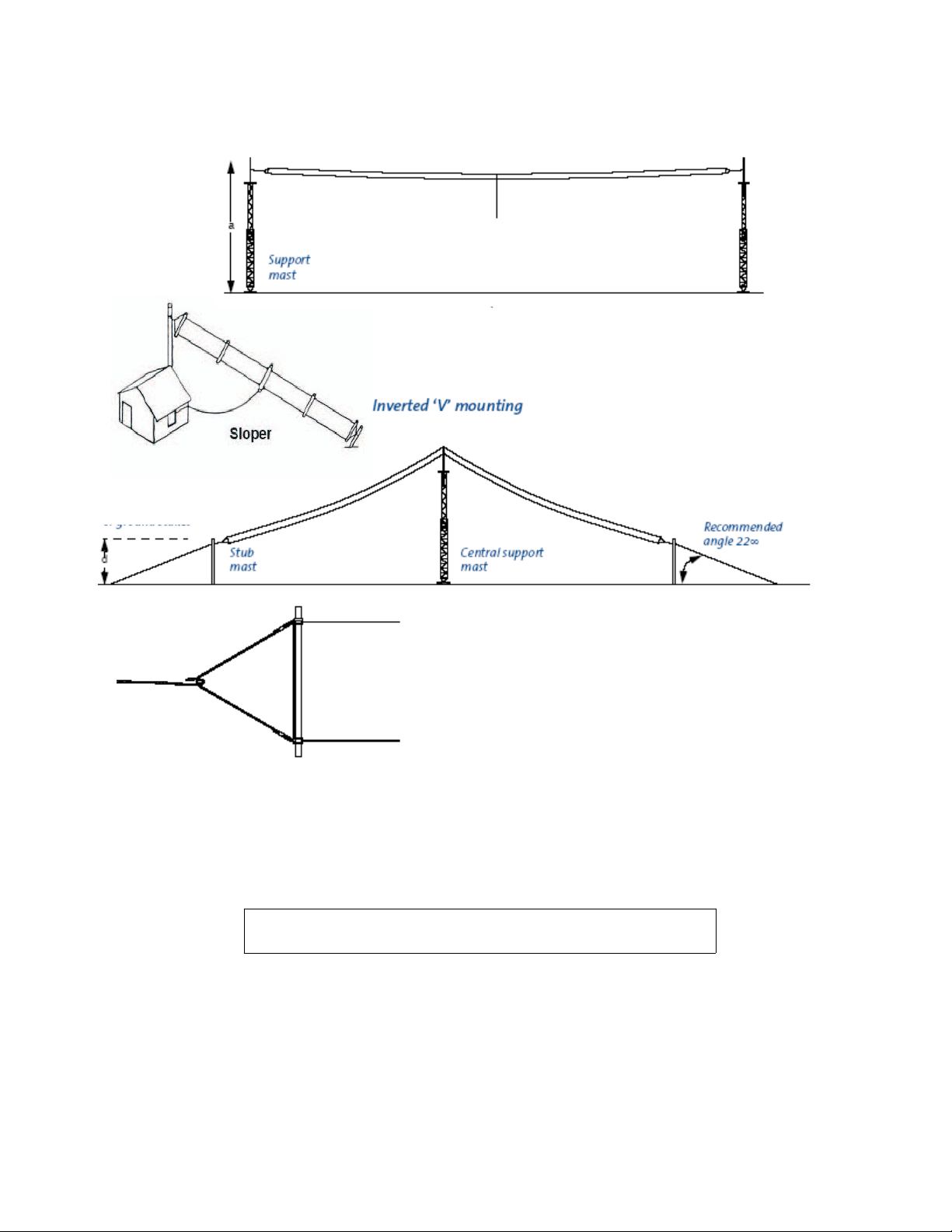
The TENNADYNE® TD series terminated folded dipole is a broadband antenna designed
for fixed station, multi-frequency applications The antenna can be mounted
horizontally between two support systems, or as an inverted ‘V’ using a single
central support mast This antenna type is widely used by military, commercial and
broadcasting services The TD antenna line is made with extremely durable stranded Copper
Clad Steel
●Pre Tuned no measuring or cutting!!
●Easy to install
●Fantastic NVIS performer
●Great for ALE Applications
●An excellent broadband antenna
●Ground Independent
Specifications:
Impedance: 50 Ohm nominal
Bandwidth :1 8-30 MHz
Length : 90 ft
Power : 1 5kw Impulse
: 500w PEP SSB
: 200w AM/FM/RTTY
Connector : SO 239
Price : Only USD 250 00
Flat top
One of the most important components in any radio station is the antenna It is important to
take time and plan out your installation
Antenna Safety
Under no circumstances will TENNADYNE
TENNADYNE®
®
be liable for any damages
or consequential damages arising from use or misuse of our products.
The installation or dismantling of any antenna near power lines is dangerous. Each year hundreds of people are killed or
injured while attempting to install or dismantle an antenna. In many cases, the victim was well aware of the dangers, but did
not take adequate steps to avoid the hazards. or your safety and proper antenna installation, read and follow all safety
precautions.
Choose an installation site for safety as well as performance.

All electric power lines, cable lines and telephone lines look alike. To be safe, ass me ANY
overhead line can kill yo
Do not place an antenna where it could potentially fall on to, or blow into a power line. To determine the SA E DISTANCE
follow these steps:
(a)Determine the proposed height of your antenna.
(b)Add the antenna length and the length of your tower mast.
(c) Double the figure.
Your answer will be the minimum safe distance from the nearest power line that you should install your antenna.
Outdoor antennas should be grounded with an approved lighting arresting device. Local codes may apply. The radio should
also be grounded to an earth ground to help protect both the radio and its user. Do not use hot water
pipes or gas lines as a ground source.
OUTDOOR ANTENNA GROUNDING-If an outside antenna system is connected to any radio receiver or transmitter, be sure
the antenna or cable system is grounded so as to provide some protection against voltage surges and built up static charges.
Section 810 of the National Electrical Code, ANSI/N PA No.70-1984, provides information with respect to proper
grounding of the mast and supporting structure, grounding of the lead-in wire to an antenna discharge unit, size of grounding
conductors, location of antenna discharge unit, connection to grounding electrodes, and requirements for the grounding
electrode. Also refer to the ARRL’s antenna safety instruction.
Installation
Installation
(1) Prepare supports, paying attention to best possible height , antenna configuration, and alignment. Do not install
parallel to power lines.
(2) Unpack the antenna. ay it on the ground, the two rolls separated and the components laying in the middle.
(3) Cut enough rope to support the antenna side tubes.
(4) Uncoil one half of the antenna. Avoid twisting, kinking. Keep the antenna taut during uncoiling. Save the coil
tubes for future storage.
(5) Install the rope as shown in the diagram above. If you keep the top arm of the rope a couple inches shorter than the
bottom arm , the antenna will hang in a proper vertical position instead of rotating flat.
(6) Attach your coax cable and raise the antenna up in the air. Again avoid twisting, kinking or springing.
(7) Run transmission line to the station. Run the transmission line down to the ground, and perpendicular to the
antenna for as far as possible. This is important Only use a sufficient length of transmission line to reach the
station
(8) Your antenna is ready for operation.

WARRANTY
TENNADYNE® guarantees each product to be free from defects in material and workmanship for 90 days from date of purchase. The warranty applies to
the original purchaser only, and we will repair or replace the product at our discretion. Under no circumstances will TENNADYNE® liable for any damages
or consequential damages arising from use or misuse of our products. Warranty is voided if product is subject to misuse, neglect, accident, improperly
installed or used in violation of the instructions furnished by us. We reserve the right to make changes in design at any time without obligation to update
previously manufactured models. This warranty is given in lieu of any other warranty, expressed or implied.
Contact Us
TENNADYNE®
Phone: 616.868.9907
FAX: 616.868.9907
Skype: WB8NDC
US Mail:
TENNADYNE®
P. O. Box 352
Alto, MI 49302
E-mail: [email protected]

Field Test Results:
MHZ TD-90 SWR Other Manufacturer SWR
1.8 1.2 3.5
2.0 1.2 2.7
3.0 1.2 1.8
4.0 1.1 1.3
5.0 1.1 1.9
6.0 1.3 2.1
7.0 1.4 1.5
8.0 1.5 2.3
9.0 1.5 2.8
10.1 1.2 3.0
11.0 1.3 1.8
12.0 1.2 1.5
13.0 1.1 1.4
14.0 1.2 1.2
15.0 1.1 1.4
16.0 1.1 1.6
17.0 1.5 2.4
18.0 1.5 2.1
19.0 1.5 2.0
20.0 1.4 1.5
21.0 1.2 1.3
22.0 1.3 1.2
23.0 1.5 1.8
24.0 1.3 1.8
25.0 1.1 1.8
26.0 1.2 1.6
27.0 1.4 1.7
28.0 1.3 1.8
29.0 1.2 2.0

Comments from Field Tester:
1. The wind/snow static. (tik tik tik sound from static discharge) is
not present with the TD 90 as it is with the other
manufacturer(OM). During mild to heavy winds, the OM can pull
a small static arc from the coaxial line and you hear the tick tick
tick in the radio speaker from it being discharged. Have had to
incorporate a tuner on the OM antenna to take this discharge
before it hits the radio. Have heard that some people added a
one meg ohm resistor from the center conductor to the ground to
eliminate this static.
2. The TD 90 has more consistent RF output. Same RF out on each
freq. With the OM output may range from 25 to 50 watts
depending the freq/swr.
3. The TD 90 RF power remains the same on all freqs.
4. The end result is the same power on all freqs being scanned or
sounded on. This would make a great ALE or WL2K antenna. It
would be great for a (GO box) easy to set up as a Dipole, Sloper
or Inverted “V”.
5. I have a mast section of fiberglass that can be used in the field
for Emergency with the TD 90.
6. The TD 90 would be a good ALL band base system. Being able to
work several freqs without the need of an auto tuner. It was easy
to erect. (one person).
7. For testing, it was in a Dipole configuration at 20 feet above the
earth. The radio used for testing was a Kenwood TS 570DG.
Measurements was made with the Kenwood built in RF
Power/SWR meter as well as a Bird 43.
8. Submitted by Dave, WB8MWG
This manual suits for next models
1
Table of contents
Other TENNADYNE Antenna manuals

Popular Antenna manuals by other brands


DX Engineering
DX Engineering DXE-TW2010 instructions

XM Satellite Radio
XM Satellite Radio GXM30 owner's manual

ELECRAFT
ELECRAFT AXB1 owner's manual

Directive Systems & Engineering
Directive Systems & Engineering DSE1445LY quick start guide

Kathrein
Kathrein HDS 166 Guide

Steren
Steren ANT-HD-070 instruction manual

MPB
MPB SEP user manual

Metronic
Metronic 415985 manual

Parsec Antennas
Parsec Antennas AUSTRALIAN SHEPHERD installation instructions

CHAMELEON
CHAMELEON CHA COUNTERPOISE KIT Operator's manual

Alpha Antenna
Alpha Antenna Base Loop quick start guide

BARKER & WILLIAMSON
BARKER & WILLIAMSON BWDI-20N quick start guide