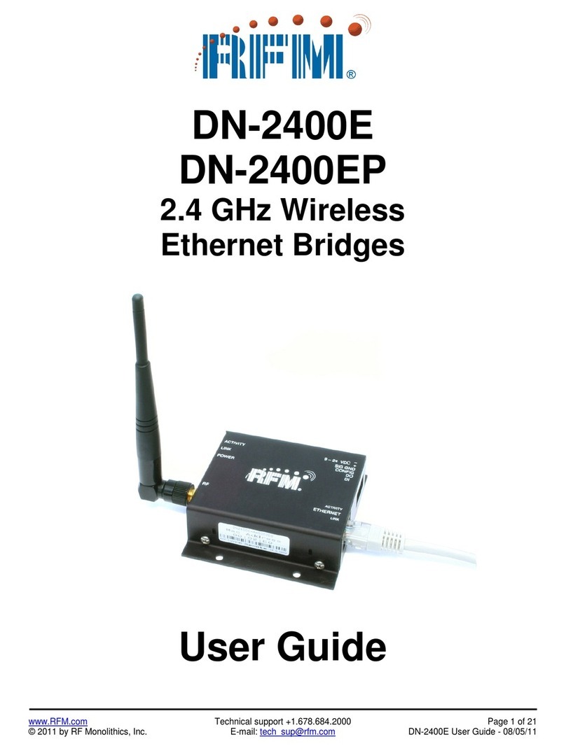
RFM SEM910 User manual

SEM910 /X /D /DX
Wireless Ethernet Bridge
User’s Guide

Important Regulatory Information
Cirronet Product FCC ID: HSW-910M
IC 4492A-910M
Note: This unit has been tested and found to comply with the limits for a Class A digital device, pursuant
to part 15 of the FCC Rules. These limits are designed to provide reasonable protection against harmful
interference when the equipment is operated in a commercial environment. This equipment generates,
uses, and can radiate radio frequency energy and, if not installed and used in accordance with the
instruction manual, may cause harmful interference to radio communications. Operation of this equipment
in a residential area is likely to cause harmful interference in which case the user will be required to correct
the interference at their expense.
FCC s MPE Requirements
Information to user/installer regarding FCC s Maximum Permissible Exposure (MPE) limits.
Notice to users/installers using the 8.5 dBi Yagi antenna with the WIT910.
FCC rules limit the use of this antenna, when connected to the WIT910 module, to point-to-point applications only.
It is the responsibility of the installer to ensure that the system is prohibited from being used in point-to-multipoint
applications, omni-directional applications, and applications where there are multiple co-located intentional radiators
transmitting the same information. Any other mode of operation using this antenna is forbidden.
Notice to WIT910 users/installers using the following fixed antennas:
Cushcraft 8.5 dBi Yagi
The field strength radiated by this antenna, when connected to a transmitting WIT910, may exceed FCC mandated
RF exposure limits. FCC rules require professional installation of these antennas in such a way that the general
public will not be closer than 23 cm from the radiating aperture of this antenna. End users of these systems must also
be informed that RF exposure limits may be exceeded if personnel come closer than 23 cm to the aperture of this
antenna.
Notice to WIT910 users/installers using the following fixed antennas:
Cushcraft 6 dBi Monopole Cushcraft 3 dBi Omni Ace 2dBi dipole
The field strength radiated by any one of these antennas, when connected to a transmitting
WIT910, may not exceed FCC mandated RF exposure limits. FCC rules require professional
installation of these antennas in such a way that the general public will not be closer than 20 cm
from the radiating aperture of any of these antennas. End users of these systems must also be
informed that RF exposure limits may be exceeded if personnel come closer than 20 cm to the
apertures of any of these antennas.
Changes or modifications not expressly approved by the party responsible may void the users ability to
operate the equipment.

Table of Contents
Introduction ...................................................................................................................................................1
Getting Started..............................................................................................................................................2
SEM910, SEM910D......................................................................................................................................3
Connectors ................................................................................................................................................4
Status Indicators........................................................................................................................................4
SEM910X/DX................................................................................................................................................5
Attaching the Remote Radio Connector – SEM910X ...............................................................................7
Attaching Remote Radio Connector – SEM910DX...................................................................................8
Configuring the SEM...................................................................................................................................10
Setting IP Addresses...............................................................................................................................10
IP Hunter Utility........................................................................................................................................10
HTML Setup ............................................................................................................................................13
Console Port............................................................................................................................................16
Filtering....................................................................................................................................................17
DHCP.......................................................................................................................................................17
SEM Operation............................................................................................................................................18
Overview..................................................................................................................................................18
Security Modes........................................................................................................................................18
Point-to-Point Mode.................................................................................................................................18
Point-to-Multipoint Mode..........................................................................................................................19
Co-located Networks...............................................................................................................................20
SEM Command Set ....................................................................................................................................21
System Commands.................................................................................................................................21
Bridge Commands...................................................................................................................................23
SEM Security Commands .......................................................................................................................24
Radio Commands....................................................................................................................................25
Specifications..............................................................................................................................................28
Connectors ..............................................................................................................................................28
Indicators.................................................................................................................................................28
Power.......................................................................................................................................................28
Troubleshooting ..........................................................................................................................................29
Technical Support....................................................................................................................................29
Warranty......................................................................................................................................................30

SEM910
Introduction
The SEM910 family of products from Cirronet™Incorporated provides wireless Ethernet
connectivity between networks located more than 5 miles apart. Built around the WIT910
frequency hopping spread spectrum data modem, SEM products provide a 10/100BaseT
connection to Ethernet networks. SEM products operate in a point-to-point mode or a point-to-
multipoint mode using a star configuration. The center of the “star” is the Master device and the
remote SEMs are Slave devices. Peer-to-peer communication is accomplished by using the
master SEM device to relay datagrams from one slave SEM device to another slave SEM device.
SEMs come in heavy duty, aluminum enclosures suitable for the rugged industrial environment.
The D models come in a DIN rail mount, rugged enclosure designed for factory and industrial
applications. The X models features a remote radio housed in a NEMA 4X/IP66 rated enclosure
that can be mounted outdoors up to 300 feet from the network connection. Communication
between SEM products is performed using the WIT910 over-the-air protocol.
SEM products are 802.3 compatible but not 802.11 compatible, provide 70Kbps full duplex data
throughput and are certified by the FCC.
The SEMs enjoy the same benefits of frequency-hopping spread spectrum technology that the
WIT910s do. Namely, the immunity to multipath fading and resistance to jamming that is
provided by changing frequency every few milliseconds.
The radios in SEM products include a robust over-the-air protocol. This protocol insures error-
free data through the use of a 24-bit CRC and ARQ to detect errors and to automatically request
a retransmission. All of this is transparent to the network which just sees complete error-free
data.
©2000- 2004 Cirronet™Inc 1 M-910-0003 Rev -

SEM910
Getting Started
The SEM family of wireless Ethernet modems is easy to install and operate. In most instances,
the only installation steps will be setting IP addresses, configuring one SEM as the master and
connecting the antenna, power and Ethernet cable. While the operation of the SEM910/D and
SEM910X/DX is the same, the installation and connection is slightly different. Please refer to the
appropriate section below for connection and installation of your product.
Setting up a pair of SEMs requires the following steps:
•Enter IP addresses into each SEM
•Configure one SEM as the Master
The default settings in the SEMs are sufficient to allow connection to Ethernet networks and to
have the slave SEM connect with the master. Other steps you may want to take include:
•Enter a default route IP address if data is to be sent off the SEM’s subnetwork (See
Ethernet Commands)
•Enable one or more of the security features of the SEM (See Security Commands)
•Adjust the RF bandwidth allocation (See Radio Commands)
•Filter out broadcast and multicast packets (See Bridge Commands)
•Change the network number (See Radio Commands)
Instructions on setting up the SEMs are detailed in the Configuring the SEM section of this
manual. Details on the various operating modes and configurations can be found the SEM
Operation section.
©2000- 2004 Cirronet™Inc 2 M-910-0003 Rev -

SEM910
SEM910, SEM910D
Figures 1, 2 & 3 show the various connectors and LEDs on the SEM910 and SEM910D.
Figure 1. SEM910 Front Panel Diagram
Figure 2. SEM910 Back Panel Diagram
Figure 3. SEM910D Front Panel Diagram
©2000- 2004 Cirronet™Inc 3 M-910-0003 Rev -

SEM910
Connectors
The RF connection on the SEM is the antenna on the top of the SEM910D. The antenna
connector is a reverse-TNC male type connector. An antenna may be connected directly to this
connector. Alternatively, an antenna may be located away from the SEM using RF cable to
connect the SEM to the antenna. Cirronet does not recommend using RF cables longer than 5
feet. If more distance is required between the SEM and the antenna Cirronet recommends using
the SEM910X/DX. If the SEM910X/DX is not used, high-quality, low-loss RF feed line must be
used.
The 10/100BaseT Ethernet connector is the standard RJ-45 connector located on the front of the
SEM910D and the rear of the SEM910. The SEM is set up to use a straight through cable to
connect to a PC. If a straight through cable is used to connect the SEM to other devices through a
hub, the SEM must be connected to the uplink port on the hub. Both a straight-through and a
crossover Ethernet cable are included.
The SYNC IN and SYNC OUT signals are provided for special applications where multiple
master SEMs are co-located. The synchronizing signals are RS-485 levels and may be connected
using an RJ-11 connector. If the sync signals are required, one of the master SEMs must be
designated as the sync master. See the section SEM/Radio Commands for details. If there are no
co-located master SEMs, sync should be left disabled.
The Console port is an RS-232 serial port that may be used to configure the SEM. Connection to
this port is made with the 9-pin to RJ-11 serial cable included with the SEM. This is useful when
the default IP address of the SEM cannot be used with the existing network preventing
configuration through a telnet session. See the section Configuring the SEM for details of using
this port.
The power connector is a 2-pin terminal block connector. The provided AC adapter provides a
12 volt power level to the SEM. The SEM can accept DC voltages ranging between 12VDC and
30VDC if alternative power supplies are to be used.
Status Indicators
The PWR indicator on the front panel indicates that power is applied to the SEM. The SEM does
not have a power switch. Power is applied and removed to the SEM by connecting and
disconnecting the power connector.
The Ethernet LEDs include LINK, TXD and RXD. The LINK LED lights when a valid Ethernet
connection is made. The SEM is set up to use a straight through cable to connect to a PC. TXD
and RXD are indicators of Ethernet data activity. They indicate the transmission and reception of
data over the Ethernet connection. Note that these LEDs can be active even when the SEM is not
communicating with another SEM.
On a slave SEM, the RF Link LED indicates the SEM has established a connection with the
master SEM. When a slave SEM is powered on, it will take a few seconds for this LED to turn
on. On a master SEM the RF Link LED is on as long as any one Slave is linked. On the X and D
models, the XCVR OK LED indicates that the remote radio assembly is connected and operating
properly.
©2000- 2004 Cirronet™Inc 4 M-910-0003 Rev -

SEM910
SEM910X/DX
Figures 4, 5 & 6 show the connectors and LEDs on the SEM910X & SEM910DX radios. Figure
7 illustrates the remote radio assembly. Connection between the SEM910X and SEM910DX
enclosures and the remote radio assembly is made through the 15-terminal connector on the front
of the radios. Digital signals, rather than RF signals are sent over the connecting cable which
may be up to 300 feet in length. These cables may be ordered from Cirronet in lengths of 100
feet to 300 feet in 100-foot increments.
Figure 4. SEM910X Front Panel Diagram
Figure 5. SEM910X Back Panel Diagram
©2000- 2004 Cirronet™Inc 5 M-910-0003 Rev -

SEM910
Figure 6. SEM910DX Front Panel Diagram
Figure 7. Remote Radio Assembly
©2000- 2004 Cirronet™Inc 6 M-910-0003 Rev -

SEM910
The remote radio assembly has mounting holes to secure the antenna. The antenna is attached to
the remote radio through the included 24-inch RF cable. If the antenna is not to be mounted on
the remote radio assembly, connection between the remote radio and the antenna must be made
with high-quality , loww-loss RF cable. Cirronet recommends limiting the length of the RF cable
to 5 feet to minimize RF signal loss.
Note: The remote radio assembly should be mounted on a tower or building top
oriented as in Figure 7. It is important that the RF connector on the remote
radio assembly point to the ground to avoid any issues with rain water.
Attaching the Remote Radio Connector – SEM910X
The figure below shows the pin numbering of the Remote Radio connector. The view provided is
looking into the side of the connector into which the pins will be inserted.
The cable pins are installed by choosing the appropriate conductor color and connector hole
location and inserting the pin into the hole until it locks into place. Verify the pin is locked into
place by gently pulling on the conductor.
If a pin is installed in the wrong connector location, use the extractor tool provided to remove the
pin. Insert the extractor tool into the connector hole such that the tool surrounds the pin. Gently
push the extractor tool completely into the hole. Remove the pin by gently pulling on the
conductor. If the pin does not come out easily, it is an indication the tool is not fully inserted. Do
not pull on the conductor forcefully as that can pull the conductor out of the pin.
Use the following color code to insert the pins into the connector:
CONNECTOR
PIN CONDUCTOR
COLOR CONNECTOR
PIN CONDUCTOR
COLOR
1 Brown 9 Green
2 Orange/Black 10 Orange
3 Black 11 Violet
4 Blue 12 Yellow
5 Tan 13 White/Black
6 Pink 14 Grey
7 White 15 White/Red
8 Red
Care must be taken to follow the color code correctly. An incorrectly assembled connector can
damage the radio or the card or both.
©2000- 2004 Cirronet™Inc 7 M-910-0003 Rev -

SEM910
Complete the assembly by placing the connector in the slot in one of the shell halves. Install the
two retaining screws on both sides of the shell and through the holes on both sides of the
connector; place the other shell half over the connector so the connector lies in the shell slot.
Secure the connector shell halves with the nuts and bolts provided.
Refer to the figures below.
Pinned connector in bottom connector shell Completed connector with top connector shell
attached.
Attaching Remote Radio Connector – SEM910DX
The figure below shows the pin numbering of the Phoenix Contact, 16 pin, 3.81mm Remote
Radio connector (P/N1803714). The view provided is facing the side of the connector with the
screw heads showing.
The cable comes with pins pre-crimped onto the conductors and is assembled by inserting a
crimped pin into a hole location, then tightening the screw to hold the pin securely. To verify the
pin is held firmly in place, gently pull on the conductor wire.
©2000- 2004 Cirronet™Inc 8 M-910-0003 Rev -

SEM910
If a pin is accidentally installed in the wrong connector location, simply loosen the screw,
remove the pin, re-insert it into the proper location hole and tighten the screw. Use the following
color code to insert the pins into the connector:
CONNECTOR
PIN CONDUCTOR
COLOR CONNECTOR
PIN CONDUCTOR
COLOR
1 Brown 9 Green
2 Orange/Black 10 Orange
3 Black 11 Violet
4 Blue 12 Yellow
5 Tan 13 White/Black
6 Pink 14 Grey
7 White 15 White/Red
8 Red
Care must be taken to follow the color code correctly. An incorrectly assembled connector can
damage the radio or the card or both. The picture below shows the completed cable assembly.
Important Note:
If an alternate source of power is used with the SEM910DX, the minimum voltage
is +12VDC +/-10%. Failure to meet this specification can result in damage to the
remote radio assembly.
©2000- 2004 Cirronet™Inc 9 M-910-0003 Rev -

SEM910
Configuring the SEM
The network that the SEM is connected to must be compatible with 10/100BaseT products.
Before connecting a default configured SEM to an active network that does not have a BOOTP
or DHCP server, ask the network system administrator for an IP address for the SEM that will
not cause any problems on the network.
Setting IP Addresses
SEMs are shipped from the factory with default settings that include a default IP address of
0.0.0.0 and a default configuration as a slave bridge. In order to set up a wireless link, alternate
IP addresses need to be assigned and one of the SEMs must be configured as a master device. If
a BOOTP or DHCP server is not present a different IP address must be assigned to the SEM. If a
DHCP server is present on the network, the IP address can be set up through it.
The Master SEM can obtain its IP address through a DHCP server residing on the Master SEM’s
local network. The slave SEMs receive their IP address through the Master SEM from the DHCP
server on the Master SEM’s local network. If the slave SEM cannot establish a link with the
master SEM, the slave SEM will need to have its IP address entered manually unless it will be
configured through the console port. If it is desired to configure the slave SEM through a
browser session instead of the console port but use a DHCP server to provide the IP address after
initial setup, a temporary IP address can be assigned manually but the IP address will need to be
reset to 0.0.0.0 to have the slave SEM obtain its IP address from the DHCP server.
IP Hunter Utility
The SEM910 CD has a device detection and IP setting utility named IP Hunter. This utility will
detect all Cirronet Ethernet devices on the local network, even those with no IP address. For
those units without an IP address, IP Hunter can set the IP address and then open a browser
session with that device to allow for further configuration. The IP Hunter will display devices
that already have IP addresses and will open browser sessions with those units, but will not
change the IP address already set.
©2000- 2004 Cirronet™Inc 10 M-910-0003 Rev -

SEM910
Open IP Hunter by double-clicking on the file iphunter.exe on the SEM910 CD. The following screen
will appear.
Click on the Search button to begin the search for Cirronet devices. Only Cirronet Ethernet devices will
be displayed as shown below.
Ethernet devices from other manufacturers will not be displayed, even if they have no IP address. Any
devices found will be displayed on the screen along with the IP address (if any), the netmask the MAC
address and the DHCP host name.
©2000- 2004 Cirronet™Inc 11 M-910-0003 Rev -

SEM910
Double-clicking on a device with an IP address of 0.0.0.0 will bring up the following dialog box.
Enter the desired IP address and the default netmask will automatically be entered as shown below. A
new Host Name may be entered if desired; however, the MAC Address cannot be changed.
Click OK and the IP address will be entered in the SEM910 and will be displayed in the IP Hunter
window as shown below.
©2000- 2004 Cirronet™Inc 12 M-910-0003 Rev -

SEM910
HTML Setup
Once an address has been assigned, double-click on the IP number to launch an HTML setup session in a
browser window. The login screen will display as shown below.
Enter the default Username, “admin” and the default Password, “Cirronet” (case sensitive).
(The password will be displayed as dots only for security purposes.)
Click on OK and the main browser window is displayed.
System Status
This dialog shows the Mode (Master or Slave) and Link (Up/Down) status of each device. (Clicking on
Refresh should be used when System Settings have been adjusted to display current status.)
©2000- 2004 Cirronet™Inc 13 M-910-0003 Rev -

SEM910
System Settings
This dialog allows the user to change the Hostname, set the Default Route, enter DNS entries or change
the Outmax (upload/download ratio for the radio) setting. If the SEM910 is to transmit data to devices not
on its subnet, a default router must be specified. To set the default routing address, enter it in the Default
Route field. Click on Apply to invoke changes, click on Cancel to discard.
System Ethernet Stats
This dialog displays statistics related to the transmission and reception of wired Ethernet data.
Radio Settings
This dialog identifies the radio and current operating mode. It also allows the user to configure radio
parameters for the Network, SPID, Master Bandwidth, Max Slaves, Power, Sync and Retries. Details on
these settings are provided in the section on Radio Commands.
©2000- 2004 Cirronet™Inc 14 M-910-0003 Rev -

SEM910
Bridge Settings
This dialog allows the user to set the Mode, (Master or Slave), any Filtering (see the section on Filtering
below) and whether or not a Login is required. Selecting “No” grays out the Username/Access-code,
Password and (Password) Verify fields. Selecting “Yes” allows entries to be entered into the fields.
Details on these settings are provided in the section on Bridge Commands.
Bridge (Connection) Status
This dialog displays statistics related to the connected radios including UserName (if no username is
assigned, N/A will display), IP Address, Radio ID and Packet/Error Information.
Access Control Settings
This dialog allows the setting of login preference, “admin” (default), “enable” or “guest”. Setting “admin”
allows the user rights to change parameters; setting “guest” limits the access to RF Tools only. After
changing the Console setting, click Apply to invoke the changes. Click on Cancel to discard any changes.
Clicking on Enable IP address control and then Apply brings up the dialog below.
Enable IP address Control
This dialog is used to designate the Allowed IP addresses from which the SEM910 will accept a telnet
session request. Simply enter an IP address in the “Allowed IP address” field and click “Add IP address.
Only IP addresses designated by this dialog can access the device when IP address control is Enabled.
©2000- 2004 Cirronet™Inc 15 M-910-0003 Rev -

SEM910
Access Control Users
This dialog allows the modification of logins and the ability to add new users.
Note: Click on Save Settings to store the system configuration changes in non-volatile FLASH
memory. The user may either click on “Reset” to reboot the processor, click on “Logout” to end the
browser session or simply close the browser window.
Console Port
The SEM can be configured two ways: Through a browser session once an IP address has been
obtained and through a serial session through the console port. The settings for the console port
are 38400 baud, 8 data bits, 1 stop bit, and no parity. The WinSEM program can be used to set
up the SEM through the Console port. The appropriate serial port must be selected in WinSEM,
but the program will automatically set up the serial port. After a few seconds the SEM firmware
version is displayed followed by the SEM> prompt.
To set the IP number of the SEM, use the ip command.
ip <xxx.xxx.xxx.xxx> {yyy.yyy.yyy.yyy}
Where x is the new IP address and y is the optional netmask number.
Once a valid IP address has been entered in the SEM, a telnet session can be established. Most
telnet programs work with the SEM. Windows 95/98/NT/2000/ME have a telnet program that
works with the SEM. A telnet session can be started by clicking on Start->Run if you have
Windows 95/98/NT/2000 and the TCP/IP client has been installed. For a SEM with an IP
address of 192.168.0.254, enter the following information in the dialog box:
telnet 192.168.0.254
A telnet window will open up prompting for a Username/Password. The default Username is
“admin”, the default Password is “Cirronet”. The first line is the version of the SEM firmware
followed by the prompt:
SEM>
If the SEM is to transmit data to devices not on its subnet, a default router must be specified. To
enter the default routing address, use the route command.
route add default <xxx.xxx.xxx.xxx> {yyy.yyy.yyy.yyy}
Where x is the IP address of the gateway device and y is the optional netmask number.
To configure a SEM as a master device, use the bridge command:
bridge master<CR>
Store the changed configuration parameters in non-volatile memory with the save command:
save<CR>
©2000- 2004 Cirronet™Inc 16 M-910-0003 Rev -

SEM910
The SEM will report back the time it took to the save the information. Reset the SEM by typing:
reset<CR>
The SEM can also be reset by cycling power. Whenever a reset is executed on the SEM, the
telnet session will be lost. It will take the SEM about 30 seconds to reinitialize after a reset or
after cycling power.
Note: Failure to save and reset will result in the factory defaults being used.
Filtering
The SEM910 includes provision for filtering of multicast and broadcast packets. In many
networks, there is sufficient multicast and/or broadcast packets to slow the overall performance
of the SEM. Based on the number of broadcast and multicast packets, they can consume a
substantial amount of the RF bandwidth. By turning filtering on, the SEM will ignore these
packets and limit transmission to packets with specific device addresses. In some instances, it
will be desired to have the SEM transmit the multicast and broadcast packets; in this instance
filtering should be disabled. Note that filtering broadcast packets also filters multicast packets
but filtering multicast packets does not filter broadcast packets. To filter broadcast and multicast
packets use the bridge filter command:
bridge filter bcast<CR>
Refer to the section Bridge Commands for details of the filter commands.
DHCP
A DHCP server can set the SEM IP address as well as the default route IP address. This is
accomplished by setting the desired default route IP address in the DHCP server using Option 3.
A DHCP server will not overwrite a previously entered default router IP address in the SEM. If a
DHCP server is not used to set the default router IP address, one must be entered using the route
command. See the previous section for details of the route command. If an IP address has
previously been entered into the SEM but a DHCP server is to be used to assign an IP address, it
will be necessary to set the IP address in the SEM to 0.0.0.0 using the ip command.
©2000- 2004 Cirronet™Inc 17 M-910-0003 Rev -
This manual suits for next models
3
Table of contents
Other RFM Network Router manuals