manuals.online logo
Brands
  1. Home
  2. •
  3. Brands
  4. •
  5. Ruckus Wireless
  6. •
  7. Network Router
  8. •
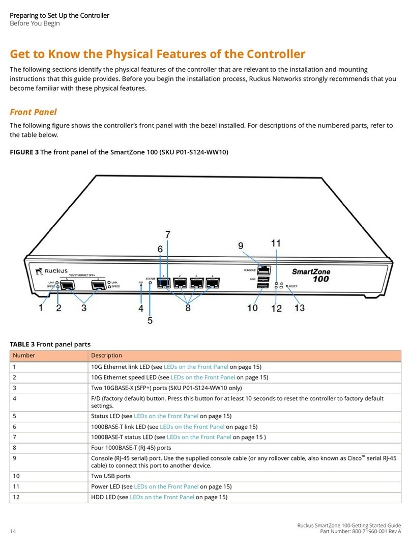
  9. Ruckus Wireless ZoneFlex P300 Installation instructions manual

Ruckus Wireless ZoneFlex P300 Installation instructions manual

Copyright © 2015 Ruckus Wireless, Inc.
Published 13 July 2015, Part Number 800-70937-001 Rev B
Page 1 of 4
ZoneFlexTM P300 Wireless Bridge
Mounting Guide
This Mounting Guide provides information on how to configure the Ruckus
Wireless ZoneFlex P300 802.11ac point-to-point and point-to-multipoint
outdoor wireless bridge on the network. The ZoneFlex P300 can use its
internal 5GHz antennas, or can optionally use a two-port customer-
ordered external 5GHz antenna. After completing the steps described in
this Guide, you will be able to use the ZoneFlex P300 wireless bridge. The
rest of this guide refers to the ZoneFlex P300 wireless bridge as the
ZoneFlex P300, root bridge, or non-root bridge.
The ZoneFlex P300 can be ordered either as an unconfigured single
ZoneFlex P300, or as a pre-configured matched pair of ZoneFlex P300s.
These ZoneFlex P300s are almost always installed in pairs, where one is
configured as a root bridge and the other as a non-root bridge.
The ZoneFlex P300 can be deployed as a root bridge connected to the
Ethernet backhaul, or can be deployed as a non-root bridge connected to
the root bridge via the wireless link. The ZoneFlex P300 can be equipped
with customer-purchased external 5GHz antennas to increase the root
bridge-to-non-root bridge connectivity range, or to increase the number of
non-root bridges that a root bridge can communicate with.
Figure 1. ZoneFlex P300s deployed as root bridge and non-root bridge
Note 1: When deployed in the root bridge--non-root bridge -to- root
bridge--non-root bridge configuration, the two wireless links must use
different SSIDs.
Note 2: When two ZoneFlex P300s are mounted closely together (for
instance, on the same pole), make sure that the active antennas are
mounted at least one meter (39.3 inches) apart. When there is more
separation, it is less likely that either ZoneFlex P300 will experience
avoidable RF interference. If possible, the units should be on different
channels, but this separation should be maintained even when the
ZoneFlex P300s are using different channels.
Before You Begin
Before deploying Ruckus Wireless products, please check for the latest
software and the release documentation.
• User Guides and Release Notes are available at
http://support.ruckuswireless.com/documents
• Software Upgrades are available at
http://support.ruckuswireless.com/software
• Open Source information is available at
http://opensource.ruckuswireless.com
• Software License and Limited Warranty are available at
http://support.ruckuswireless.com/warranty
Safety Warnings
•WARNING! Only trained and qualified personnel should be allowed to
install, replace, or service this equipment. The professional installer is
responsible for the proper installation and configuration of this
ZoneFlex P300. The ZoneFlex P300 installation must comply with local
regulatory requirements, especially with those regulating operation
near military and/or weather radar systems.
•WARNING! Installation of this equipment must comply with local and
national electrical codes.
•WARNING! Ruckus Wireless strongly recommends that you wear eye
protection before mounting the ZoneFlex P300.
•WARNING! The Ruckus Wireless PoE injector (ordered separately) is
for indoor use only. Never mount the PoE injector outdoors with the
ZoneFlex P300.
•CAUTION: Make sure that you form a 80mm - 130mm (3”-5”) drip
loop in any cable that is attached to the ZoneFlex P300 or the building.
This will prevent water from running along the cable and entering the
ZoneFlex P300 or the building where the cable terminates.
•CAUTION: Be sure that grounding is available and that it meets local
and national electrical codes. For additional lightning protection, use
lightning rods and lightning arrestors.
•NOTE: Allowable external antenna types and antenna gains may be
limited by local regulatory requirements.
Package Contents
Before deploying your ZoneFlex P300, verify that all items listed below are
included in the package. If any item is damaged or missing, notify your
authorized Ruckus Wireless sales representative.
One or two ZoneFlex P300 kits, depending on ordered part:
• 901-P300-xx01, ZoneFlex P300, 802.11ac 5GHz point-to-point
wireless bridge, includes one ZoneFlex P300 kit
• 901-P300-xx02, ZoneFlex P300, 802.11ac 5GHz point-to-point
wireless bridge, pre-provisioned pair, includes two ZoneFlex P300 kits
where ‘xx’ is a country-specific code.
Each ZoneFlex P300 kit contains:
• One ZoneFlex P300, which includes a 12mm stainless steel M6x1
Phillips earth ground screw with split lock and flat washers (A in Figure
2)
• One M25 data cable gland (B in Figure 2)
• One green/yellow earth ground wire with ring terminal (C in Figure 2)
• One wall- or pole-mounting bracket (D in Figure 2)
• One U-joint bracket (E in Figure 2)
• One linkage bracket with two serrated external-tooth lock washers (F
in Figure 2)
• One ZoneFlex P300 bracket (G in Figure 2)
• Two sets 50mm stainless steel M8x1.25 hex bolt with split lock and
flat washers (H in Figure 2)
• Four SAE32-sized stainless steel clamps, 38.1mm to 63.5mm (1.5" to
2.5") inner diameter (I in Figure 2)
• Four sets stainless steel 8mm M4x0.7 pan head Phillips screws with
split lock and flat washers (J in Figure 2)
• Eight sets stainless steel 0.5-inch x 0.250-28 hex bolt with split lock
and flat washers (K in Figure 2)
• Service Level Agreement/Limited Warranty Statement
• Regulatory Statement
• Declaration of Conformity, if required
• ZoneFlex P300 Wireless Bridge Quick Setup Guide
• This Mounting Guide
•N-Type Connector Sealing Instructions
NOTE: This kit includes extra bolts, nuts and washers. You may use the
extras wherever required.
Figure 2. ZoneFlex P300 field-installation kit contents
LEDs and Indications
The ZoneFlex P300 has five LEDs visible on the outside of the chassis. The
LEDs have two different operating modes, and the LEDs can be manually
turned on and off by the operator. Refer to Table 1 for a description of
these LEDs and their operating modes.
Note: This Mounting Guide is designed to work with the ZoneFlex
P300 Wireless Bridge Quick Setup Guide. Complete the procedures
in the Quick Setup Guide before continuing with this document.
Note: The minimum software revision for the P300 is base image
100.1.0.9 or later. FlexMaster requires firmware 9.12 and later to
manage the P300.
non-root bridge
non-root bridge
root bridge
root bridge
non-root bridge
Table 1. ZoneFlex P300 LED indications
LED Normal Mode Aiming Mode (all green)
PWR • Red = booting
• Green = normal
operation
Aiming Strength 4
• Solid: Min + 36 RSSI (RSSI >= 42)
• Blinking: Min + 32 RSSI
(42> RSSI >= 36)
CTL • Off = standalone
operation
• Other modes = to be
determined
Aiming Strength 3
• Solid: Min + 24 RSSI (36 > RSSI >= 30)
• Blinking: Min + 18 RSSI
(30 > RSSI >= 24)
ROOT • Off = non root bridge
• Solid green = root
bridge
Aiming Strength 2
• Solid: Min + 12 RSSI (24 > RSSI >= 18)
• Blinking: Min + 6 RSSI
(18 > RSSI >= 12)
5G • Off = radio down
• Solid green = radio
up & link up
• Flashing green =
radio up but no link
Aiming Strength 1
• Solid: RSSI >= Configured Minimum
(12 > RSSI >= 6)
• Blinking: RSSI < Configured minimum
(Default: 6 which is configurable)
F G
H
EA C
BD
IJ K
Copyright © 2015 Ruckus Wireless, Inc.
Published 13 July 2015, Part Number 800-70937-001 Rev B
Page 2 of 4
Continue with the following:
•Configuring the ZoneFlex P300
•Physical Installation
•Troubleshooting
CONFIGURING THE ZONEFLEX P300
Refer to the ZoneFlex P300 Wireless Bridge Quick Setup Guide. After you
have completed the procedures in that guide, continue with Physical
Installation.
PHYSICAL INSTALLATION
There are some information that you need to install the ZoneFlex P300:
•Aiming and Reset Buttons
•Aiming Point-to-Point ZoneFlex P300s
•Aiming Point-to-Multipoint ZoneFlex P300s
•General Installation Notes
•Step 1: Verifying the Package Contents
•Step 2: Collecting Tools and Materials
•Step 3: Assembling the RJ-45 Cable and the Cable Gland
•Step 4: Attaching the U-Joint Bracket to the Mounting Bracket
•Step 5a: Attaching the Mounting Bracket to a Flat Surface
•Step 5b: Attaching the Mounting Bracket to a Metal Pole
•Step 6: Mounting the Linkage Bracket to the U-Joint Bracket
•Step 7: Assembling the P300 Bracket and the ZoneFlex P300
•Step 8: Attaching the P300 Bracket and ZoneFlex P300 to the Linkage
Bracket
•Step 9: Mounting and Connecting a 5GHz External Antenna (optional)
•Step 10: Earth Grounding the ZoneFlex P300 (optional)
•Step 11: Connecting and Sealing the RJ-45 Cable
Aiming and Reset Buttons
The ZoneFlex P300 has two buttons inside the PoE IN port: the Aiming
button and the Reset button. The Aiming button is inside the ZoneFlex
P300 closer to the ZoneFlex P300 LEDs (A in Figure 3), and the Reset
button is inside the ZoneFlex P300 farther away from the ZoneFlex P300
LEDs (B in Figure 3).
Figure 3. ZoneFlex P300 Aiming and Reset buttons
• Press and hold the Aiming button (closer to the LEDs) to put the
ZoneFlex P300 into aiming mode, and then point the ZoneFlex P300
antenna toward the far-end ZoneFlex P300 antenna. Note: The P300
remains in aiming mode for 15 minutes after aiming is started.
• Press the Reset button (farther away from the LEDs) to reboot the
ZoneFlex P300.
• Press and hold the Reset button (farther away from the LEDs) for six
seconds to reset the ZoneFlex P300 to factory defaults.
CAUTION: DO NOT DO THIS UNLESS SO INSTRUCTED. Doing this
resets the ZoneFlex P300 IP address to 192.168.2.1.
Aiming Point-to-Point ZoneFlex P300s
The ZoneFlex P300 throughput depends on an accurate alignment of the
two communicating ZoneFlex P300s, because the highest throughput is
generally achieved with the strongest signal. The ZoneFlex P300 is
equipped with an internal aiming function that is based on the received
signal strength indicator (RSSI) power measurement. Note: Table 1 lists
the signal strengths associated with each of the LEDs.
1Press and hold the Aiming button (closer to the LEDs) to put the Zone-
Flex P300 into aiming mode, and then point the ZoneFlex P300
antenna toward the far-end ZoneFlex P300 antenna. (The P300
remains in aiming mode for 15 minutes after aiming is started.)
2Use the 5G through PWR LEDs to determine the signal strength.
When all four 5G through PWR LEDs are solid green, the ZoneFlex
P300 is receiving the strongest signal possible. If some LEDs are flash-
ing green or off, reposition the ZoneFlex P300 antenna to achieve a
better signal. When the highest number of LEDs are solid green,
tighten the antenna or ZoneFlex P300 mount to align the antenna with
the strongest signal.
3Repeat this procedure for the far-end ZoneFlex P300.
4Continue with the ZoneFlex P300 Wireless Bridge User Guide to verify
association between the ZoneFlex P300s.
Aiming Point-to-Multipoint ZoneFlex P300s
In a point-to-multipoint installation, the aiming procedure is slightly
different.
1Choose the “optimal pair” (one root bridge and one non-root bridge)
for your network. The “optimal pair” can be determined by placement
location, throughput requirements, or other factors.
For example, if you are installing three non-root bridges spaced away
from each other, you would likely want to choose the one closest to
the middle of the root bridge coverage area. This can help provide an
optimal balance of performance for all three non-root bridges.
2Complete the aiming procedure for the selected “optimal pair” first, as
described in Aiming Point-to-Point ZoneFlex P300s.
3Repeat the aiming procedure for each additional non-root bridge,
while leaving the root bridge antenna fixed.
4Continue with the ZoneFlex P300 Wireless Bridge User Guide to verify
association between the ZoneFlex P300s.
General Installation Notes
• The ZoneFlex P300 wireless links perform best when the ZoneFlex
P300s are mounted within line of sight of each other (see Figure 1). In
general, Ruckus Wireless recommends installing ZoneFlex P300s
away from obstructions and sources of interference.
• Ruckus Wireless also recommends installing the root bridge on the
network end of the bridged link and the non-root bridge on the remote
end.
• In a point to multipoint configuration, there are many factors to
consider. First, note that the maximum angle from the root bridge is
30 degrees when using the internal antenna, and is whatever angle is
supported by an external antenna. As you get closer to the maximum
angle supported by the antenna, throughput performance decreases.
If you go beyond the supported antenna angle, performance is
drastically impacted to the point that connectivity may be completely
lost.
Second, consider the difference in distance from the root bridge. If one
non-root bridge is at placed at a great distance from the root bridge,
and another non-root bridge is very close, performance may be
impacted due to different time delays between the two transmission
links.
• The ZoneFlex P300 can use its internal 5GHz antennas, or can
optionally use a two-port external 5GHz antenna.
• The minimum distance between ZoneFlex P300 antennas is 1 meter
(39.3 inches).
•SeeFigure 4 for installation components for a typical outdoor ZoneFlex
P300 installation.
Figure 4. Typical PoE installation components
Step 1: Verifying the Package Contents
Before deploying your ZoneFlex P300 in the field, verify that all items listed
in Package Contents are included in the package. If any item is damaged
or missing, notify your authorized Ruckus Wireless sales representative.
Step 2: Collecting Tools and Materials
• Torque wrench or torque screwdriver with sockets and bits
• Adjustable wrench
• Customer-supplied outdoor-rated Cat5e UTP RJ-45 Ethernet cable
with 4.0mm to 6.5mm (0.17" to 0.26") round cable sheath
• Thin probe
If you are mounting the ZoneFlex P300 on a flat surface, then you will also
need:
• Customer-supplied wall anchors with up to M6 or 0.25” stainless steel
screws rated to withstand 128 N or 28.8 lbf (required to withstand
wind loads of 266km/h or 165mph)
• Electric drill with drill bits and customer-supplied wall anchors
If you are mounting the ZoneFlex P300 on a pipe or pole, then you will also
need:
• A 38.1mm to 63.5mm (1.5" to 2.5") pipe or pole
• Four factory-supplied steel clamps
Continue with Step 3: Assembling the RJ-45 Cable and the Cable Gland.
AIM • Green = aiming
mode
• Off = normal mode
• Green = aiming mode (Note)
• Off = normal operation mode
Note: The P300 remains in aiming mode for 15 minutes after aiming is
started.
Table 1. ZoneFlex P300 LED indications
LED Normal Mode Aiming Mode (all green)
BA
Indoor
Router
or switch Cat5 Ethernet
cables
Surge
protector
Outdoor
Drip
loop
Drip
loop
Ground
rod
Ground
screw
Outdoor-rated
Cat5e UTP cable
5.5mm2(10AWG)
min solid-core wire
ZoneFlex P300
Wireless Bridge
AC cable
PoE
injector
Copyright © 2015 Ruckus Wireless, Inc.
Published 13 July 2015, Part Number 800-70937-001 Rev B
Page 3 of 4
Step 3: Assembling the RJ-45 Cable and the Cable
Gland
The ZoneFlex P300 uses one RJ-45 cable for data and Power over
Ethernet (PoE) as shown in Figure 4. Assemble the ZoneFlex P300 end of
the cable and the M25 data cable gland as shown in Figure 5.
1Using the adjustable wrench, remove the cable gland from the Zone-
Flex P300.
2Feed the end of the RJ-45 cable through the sealing nut (D in Figure
5), rubber sealing insert (C), clamping ring assembly (B) and cable
gland base (A).
Figure 5. RJ-45 cable and cable gland assembly
3Connect a PoE-powered cable to the Ethernet port in the ZoneFlex
P300.
4After the ZoneFlex P300 boots up, verify that the PWR LED on the
ZoneFlex P300 is a steady green.
NOTE: The ZoneFlex P300s at both end of each link need to be powered
on to complete the aiming steps.
NOTE: DO NOT ASSEMBLE THE CABLE GLAND TO THE ZONEFLEX
P300 AT THIS TIME!
Continue with Step 4: Attaching the U-Joint Bracket to the Mounting
Bracket.
Step 4: Attaching the U-Joint Bracket to the
Mounting Bracket
1Position the U-joint bracket on the mounting bracket.
NOTE: Mount the U-joint bracket in any direction on the mounting bracket,
preferably to allow ZoneFlex P300 azimuth adjustments. Then the ZoneFlex
P300 bracket allows ZoneFlex P300 elevation adjustments.
Figure 6. U-joint bracket attached horizontally to the mounting bracket
2Use four 0.250-28 hex bolt and washer sets (A) to mount the U-joint
bracket (B) to the mounting bracket (C). Tighten the bolts to 9.5 N.m
(7 ft-lbs).
Continue with Step 5a: Attaching the Mounting Bracket to a Flat Surface or
Step 5b: Attaching the Mounting Bracket to a Metal Pole.
Step 5a: Attaching the Mounting Bracket to a Flat
Surface
Note: The minimum distance between ZoneFlex P300 antennas is 1 meter
(39.3 inches).
1Place the mounting bracket at the location on the flat surface where
you want to mount the ZoneFlex P300. Use the holes on the mounting
bracket as a template to mark the locations of the mounting holes.
Figure 7. Mounting bracket flat surface holes
2Remove the mounting bracket from the flat surface.
3Drill holes required for the mounting hardware.
4Attach the mounting bracket to the flat surface using the mounting
hardware.
5Using the mounting hardware instructions, tighten the hardware to
secure the mounting bracket.
Continue with Step 6: Mounting the Linkage Bracket to the U-Joint
Bracket.
Step 5b: Attaching the Mounting Bracket to a Metal
Pole
Note: The minimum distance between ZoneFlex P300 antennas is 1 meter
(39.3 inches).
1Insert the open end of one steel clamp into the upper two slots on the
mounting bracket.
2Take the other steel clamp and insert it into the lower two slots on the
mounting bracket.
NOTE: The clamps can be daisy-chained together to accommodate larger
poles.
3Use the clamps to attach the mounting bracket to the pole. Tighten
the clamps to 3 N.m or 27 in-lbs, or per manufacturer’s specifications.
Figure 8. Attaching the mounting bracket to a vertical pole
Continue with Step 6: Mounting the Linkage Bracket to the U-Joint
Bracket.
Step 6: Mounting the Linkage Bracket to the U-Joint
Bracket
The linkage bracket attaches to the U-joint bracket using an M8 bolt and
washer set. The linkage bracket is symmetrical, and either end can be
attached to the U-joint bracket.
NOTE: Make sure that linkage bracket is installed with its serrated external-
tooth lock washer on the inside of the U-joint bracket flanges. This ensures
that the azimuth adjustment does not change.
1Loosely assemble the linkage bracket (A), the U-joint bracket (B), one
serrated external-tooth lock washer (C), and one M8 bolt and washer
set (D).
Figure 9. Attaching the linkage bracket to the U-joint bracket
2If the ZoneFlex P300 is going to use its internal 5GHz antenna, then
use the procedure described in Aiming Point-to-Point ZoneFlex P300s
to set the azimuth for the best ZoneFlex P300 reception.
3Tighten the M8 bolt to 13.6 N-m (10 ft-lbs).
NOTE: You may need to repeat this aiming procedure at the far end of the
ZoneFlex P300 link.
Continue with Step 7: Assembling the P300 Bracket and the ZoneFlex
P300.
Step 7: Assembling the P300 Bracket and the
ZoneFlex P300
1Place the P300 bracket onto the back side of the ZoneFlex P300 so
that the four larger screw holes on the bracket align with the four
screw holes on the ZoneFlex P300. Make sure that the end of the
P300 bracket with the hoisting loop is on the same side as the Zone-
Flex P300 N-type antenna connectors.
Figure 10. Attaching the P300 bracket to the ZoneFlex P300
A
B
C
D
C
B
A
A
C
B
D
Copyright © 2015 Ruckus Wireless, Inc.
Published 13 July 2015, Part Number 800-70937-001 Rev B
Page 4 of 4
2Use four 8mm M4x0.7 pan head Phillips screw with split lock and flat
washer sets to mount the P300 bracket to the ZoneFlex P300. Tighten
the screws to 2.5-3.0 N.m or 22-27 in-lbs.
CAUTION: Make sure that the screws are no longer than 8mm. If a screw
is longer than 8mm, it can damage the ZoneFlex P300 chassis.
Continue with Step 8: Attaching the P300 Bracket and ZoneFlex P300 to
the Linkage Bracket.
Step 8: Attaching the P300 Bracket and ZoneFlex
P300 to the Linkage Bracket
The P300 bracket attaches to the linkage bracket using an M8 bolt and
washer set. The linkage bracket is symmetrical, and either end can be
attached to the P300 bracket.
NOTE: Make sure that linkage bracket is installed with its serrated external-
tooth lock washer on the inside of the P300 bracket flanges. This ensures
that the elevation adjustment does not change.
1If required, then suspend the ZoneFlex P300 by attaching a carabiner
to the hoisting loop on the P300 bracket.
2As described in Step 6: Mounting the Linkage Bracket to the U-Joint
Bracket, loosely assemble the P300 bracket (shown in Figure 10), the
linkage bracket (A in Figure 9), the second serrated external-tooth lock
washer (B), and the second M8 bolt and washer set (D).
CAUTION: Make sure that the PoE IN port points downward to help
prevent water intrusion.
Figure 11. P300 bracket and ZoneFlex P300 attached to the linkage bracket on pole
3If the ZoneFlex P300 is going to use its internal 5GHz antenna, then
use the procedure described in Aiming Point-to-Point ZoneFlex P300s
to set the elevation for the best ZoneFlex P300 reception.
4Tighten the M8 bolt to 13.6 N-m (10 ft-lbs).
NOTE: You may need to repeat this aiming procedure at the far end of the
ZoneFlex P300 link.
CAUTION: If you are not connecting external antennas to the ZoneFlex
P300, then make sure that the metal caps remain installed and securely
fastened to protect the interfaces from elements, such as water and dirt.
Continue with Step 9: Mounting and Connecting a 5GHz External Antenna
(optional).
Step 9: Mounting and Connecting a 5GHz External
Antenna (optional)
Note: The minimum distance between ZoneFlex P300 antennas is 1 meter
(39.3 inches).
1Disconnect the ZoneFlex P300 from the PoE power source.
2Unscrew the metal caps that protect the ZoneFlex P300 antenna con-
nectors. Place the metal caps in a safe place for later use.
3If the antennas come with RF coaxial cables (for example, a patch
antenna), then physically mount the antennas at your desired location,
preferably on the same mounting structure as the ZoneFlex P300.
NOTE: Mount the external antennas at least 20cm (7.9”) away from each
other and other antennas.
4Connect the 5GHz antenna(s) to one or both of the female N-type
antenna connectors on the ZoneFlex P300. Use a torque wrench to
tighten the connectors to 1.58 N.m (14 in-lbs).
If you are using a single-port antenna, then you can use either Zone-
Flex P300 antenna port.
5Apply weatherproofing tape to the antenna connectors as described in
the N-Type Connector Sealing Instructions.
6Reconnect both ZoneFlex P300s to their PoE power sources.
7Using the procedure described in Aiming Point-to-Point ZoneFlex
P300s, set the azimuth and elevation for the best reception on both
ZoneFlex P300s.
CAUTION: If you are not connecting external antennas to the ZoneFlex
P300, then make sure that the metal caps remain installed and securely
fastened to protect the connectors from elements, such as water and dirt.
Continue with Step 10: Earth Grounding the ZoneFlex P300 (optional).
Step 10: Earth Grounding the ZoneFlex P300
(optional)
CAUTION: Make sure that earth grounding is available and that it meets
local and national electrical codes. For additional lightning protection, use
lightning rods and lightning arrestors.
NOTE: The color coding of ground wires varies by region. Before
completing this step, check your local wiring standards for guidance.
• Using the factory-supplied ground wire and ground screw/washer set,
connect a good earth ground to the ZoneFlex P300 chassis ground
point (see Figure 12).
CAUTION: The ZoneFlex P300 includes a 12mm stainless steel M6x1
earth ground screw with split lock and flat washers. Make sure that any
replacement screw is no longer than 12mm. If a screw is longer than
12mm, it can damage the ZoneFlex P300 chassis.
Figure 12. Connect good earth ground to ZoneFlex P300 here
Continue with Step 11: Connecting and Sealing the RJ-45 Cable.
Step 11: Connecting and Sealing the RJ-45 Cable
The ZoneFlex P300 uses one RJ-45 cable for Power over Ethernet (PoE).
Connect and seal the cable using the M25 data cable gland.
1If not already done, then use the instructions in Step 3: Assembling the
RJ-45 Cable and the Cable Gland to assemble the RJ-45 cable, seal-
ing nut (D in Figure 13), rubber sealing insert (C), clamping ring assem-
bly (B) and cable gland base (A).
Figure 13. RJ-45 cable and cable gland assembly
2If not already done, then connect the cable to the Ethernet port in the
ZoneFlex P300.
3Tighten the cable gland base into the ZoneFlex P300 chassis to 7 N.m
or 62 in-lbs.
4Wrap the clamping ring assembly around the rubber sealing insert.
Make sure that the clamping ring assembly fully encloses the rubber
sealing insert.
5Seat the clamping ring assembly and rubber sealing insert in the cable
gland base.
6Tighten the sealing nut to 1.1 N.m or 10 in-lbs, or until the rubber seal-
ing insert is compressed.
Congratulations! You have mounted your ZoneFlex P300.
TROUBLESHOOTING
CAUTION: If required, you can reset the ZoneFlex P300 to its factory
default settings by pressing and holding the reset button located inside the
PoE IN port, on the side farther from the ZoneFlex P300 LEDs, for six
seconds. DO NOT DO THIS UNLESS SO INSTRUCTED. (Doing this resets
the ZoneFlex P300 IP address to 192.168.2.1.)
NOTE: After a reset, you can access the internal ZoneFlex P300 web
interface using https://192.168.2.1 for a root bridge or https://
192.168.2.254 for a non-root bridge). Your device must use any other
address from 192.168.2.2 through 192.168.2.253, with subnet mask
255.255.255.0. The username is super, and the password is sp-admin.
Refer to the ZoneFlex P300 Wireless Bridge User Guide available at
https://support.ruckuswireless.com.
NOTE: After an ZoneFlex P300 is removed from its mounting, it may drip
some water from the channel surrounding the radome. As long as the
ZoneFlex P300 has been operating normally, this incidental water
collection and dripping is normal, and is not service-affecting.
A
B
C
D

Other manuals for ZoneFlex P300

6

Other Ruckus Wireless Network Router manuals

Ruckus Wireless ZoneFlex 7731 User manual

Ruckus Wireless

Ruckus Wireless ZoneFlex 7731 User manual

Ruckus Wireless 2825 User manual

Ruckus Wireless

Ruckus Wireless 2825 User manual

Ruckus Wireless MF2900 User manual

Ruckus Wireless

Ruckus Wireless MF2900 User manual

Ruckus Wireless MediaFlex 2111 User manual

Ruckus Wireless

Ruckus Wireless MediaFlex 2111 User manual

Ruckus Wireless ICX 7150-C12P Manual

Ruckus Wireless

Ruckus Wireless ICX 7150-C12P Manual

Ruckus Wireless SmartZone 100 User manual

Ruckus Wireless

Ruckus Wireless SmartZone 100 User manual

Ruckus Wireless Ruckus ICX 7150 Series Manual

Ruckus Wireless

Ruckus Wireless Ruckus ICX 7150 Series Manual

Ruckus Wireless SmartZone 100 User manual

Ruckus Wireless

Ruckus Wireless SmartZone 100 User manual

Ruckus Wireless SmartZone 100 User manual

Ruckus Wireless

Ruckus Wireless SmartZone 100 User manual

Ruckus Wireless ZoneDirector 1200 User manual

Ruckus Wireless

Ruckus Wireless ZoneDirector 1200 User manual

Ruckus Wireless ZoneDirector Series User manual

Ruckus Wireless

Ruckus Wireless ZoneDirector Series User manual

Ruckus Wireless SmartZone 100 User manual

Ruckus Wireless

Ruckus Wireless SmartZone 100 User manual

Ruckus Wireless 2825 User manual

Ruckus Wireless

Ruckus Wireless 2825 User manual

Ruckus Wireless ICX Series User manual

Ruckus Wireless

Ruckus Wireless ICX Series User manual

Ruckus Wireless MediaFlex NG User manual

Ruckus Wireless

Ruckus Wireless MediaFlex NG User manual

Ruckus Wireless SmartZone 3.2 User manual

Ruckus Wireless

Ruckus Wireless SmartZone 3.2 User manual

Popular Network Router manuals by other brands

Leonton ET5-0800 Series user manual

Leonton

Leonton ET5-0800 Series user manual

NETGEAR C3000v2 user manual

NETGEAR

NETGEAR C3000v2 user manual

Helmholz REX 100 3G quick start guide

Helmholz

Helmholz REX 100 3G quick start guide

Cisco 2620 Configuration guide

Cisco

Cisco 2620 Configuration guide

D-Link DIR-855L Quick install guide

D-Link

D-Link DIR-855L Quick install guide

NETGEAR C6300 user manual

NETGEAR

NETGEAR C6300 user manual

H3C S5830V2 series Security configuration guide

H3C

H3C S5830V2 series Security configuration guide

ELPRO 2080E-T installation guide

ELPRO

ELPRO 2080E-T installation guide

Robustel GoRugged R2000 user guide

Robustel

Robustel GoRugged R2000 user guide

Fritz! Box 6490 cable quick guide

Fritz!

Fritz! Box 6490 cable quick guide

Kortex KX ROUTER 3G PRO user manual

Kortex

Kortex KX ROUTER 3G PRO user manual

TP-Link Deco M9 Plus manual

TP-Link

TP-Link Deco M9 Plus manual

Brite View BV-254 user manual

Brite View

Brite View BV-254 user manual

PowerNet HomePNA 3.0 user manual

PowerNet

PowerNet HomePNA 3.0 user manual

E-TOP NR620M Quick setup guide

E-TOP

E-TOP NR620M Quick setup guide

Westermo MRD-350 user guide

Westermo

Westermo MRD-350 user guide

Black Box LW6005A user manual

Black Box

Black Box LW6005A user manual

Etec XG-506RT user manual

Etec

Etec XG-506RT user manual

manuals.online logo
manuals.online logoBrands
  • About & Mission
  • Contact us
  • Privacy Policy
  • Terms and Conditions

Copyright 2025 Manuals.Online. All Rights Reserved.