RICE HYDRO EL Series User manual

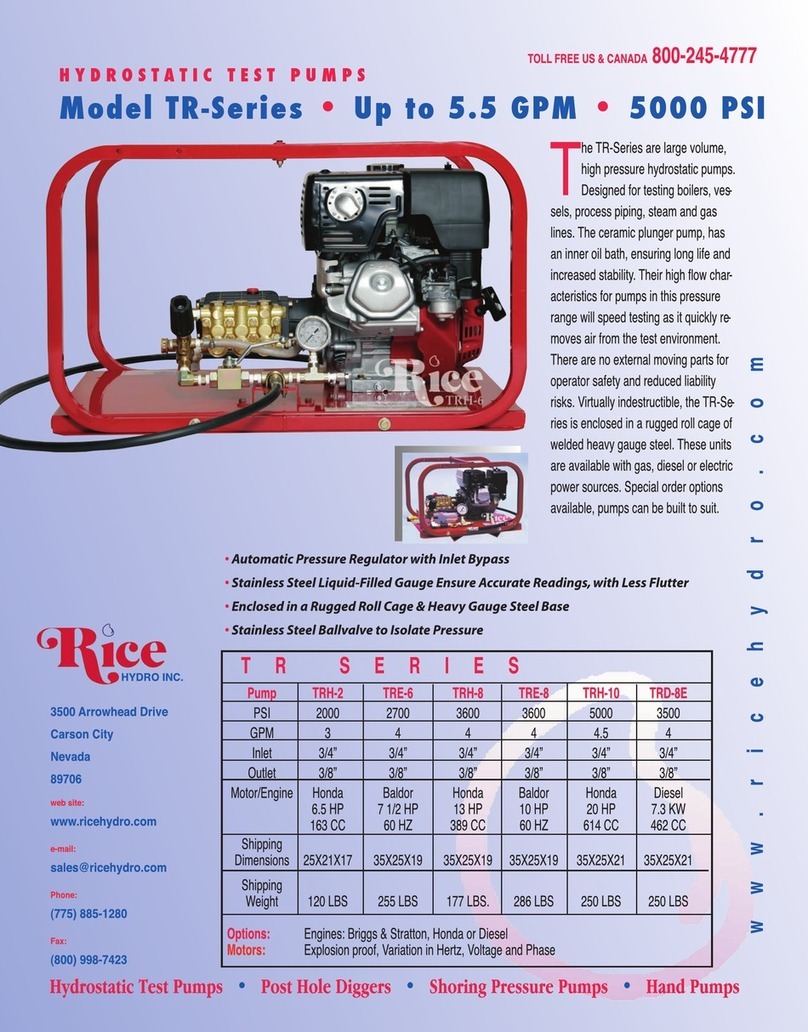
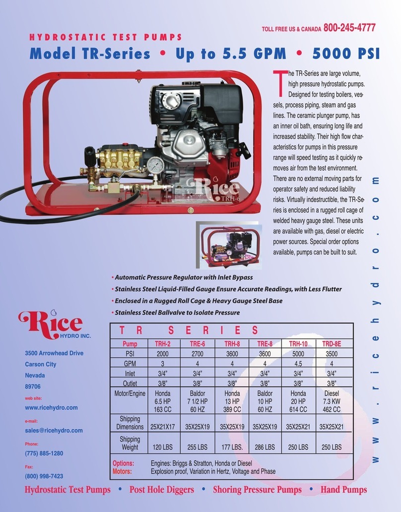
The El-series is a line of low volume high pressure hydrostatic test pumps,
offering flow rates up to 5 GPM, and pressures to 1800 PSI. Designed for
testing sprinkler systems, irrigation lines, pressure vessels, plant process
piping, and small diameter water lines. The triplex ceramic plunger pump has an
inner oil bath, ensuring long life
with minimal maintenance.
Standard motor features include;
overload protection, totally
enclosed fan cooled, 110 to 220
volt, and the 1 HP motors are
capable of reading 50/60 Hertz.
There are no external moving
parts for increased operator safety
and reduced liability risk. All RICE
units can be “Built to Suit”, contact
the factory for special order
options available or details on
your required specifications.
E L E R I E
MODEL EL1 EL1A EL2 EL3 EL4/18 EL5/500
PSI 300 500 1000 1500 1800 500
GPM 331.5 1.5 45
INLET 3/4” 3/4” 3/4” 3/4” 3/4” 3/4”
OUTLET 1/2” 1/2” 3/8” 3/8” 3/8” 1/2”
MOTOR 1/2HP 1HP 1HP 1.5HP 5HP 2HP
60HZ 50/60HZ 50/60HZ 50/60HZ 60HZ 60HZ
110/220 110/220 110/220 110/220 220 110/220
DIMENSIONS 22X14X14 22X14X14 22X14X14 22X14X14 25X21X17 25X21X17
WEIGHT 60 LBS 74 LBS 85 LBS 86 LBS 175 LBS 125 LBS
OPTION : Explosion Proof, Phase, Hertz and oltage options available
H YD RO S T AT I C T E S T P U MPS
Model E L - S eri es •5 GPM •1800 PS I
w w w . r i c e h y d r o . c o m
HYDRO INC.
3500 Arrowhead Drive
Carson City
Nevada
89706
web site:
www.ricehydro.com
e-mail:
Phone:
(775) 885-1280
Fax:
(800) 998-7423
TOLL FREE U & CANADA 800-245-4777
•A tomatic Press re Reg lator with Inlet Bypass
•Stainless Steel Liq id-Filled Ga ge Ens res Acc rate Readings, with Less Fl tter
•R gged Roll Cage Constr ction, Protects P mp From Damage
•High Press re Ballvalve and Fittings

RICE HYDRO, INC.
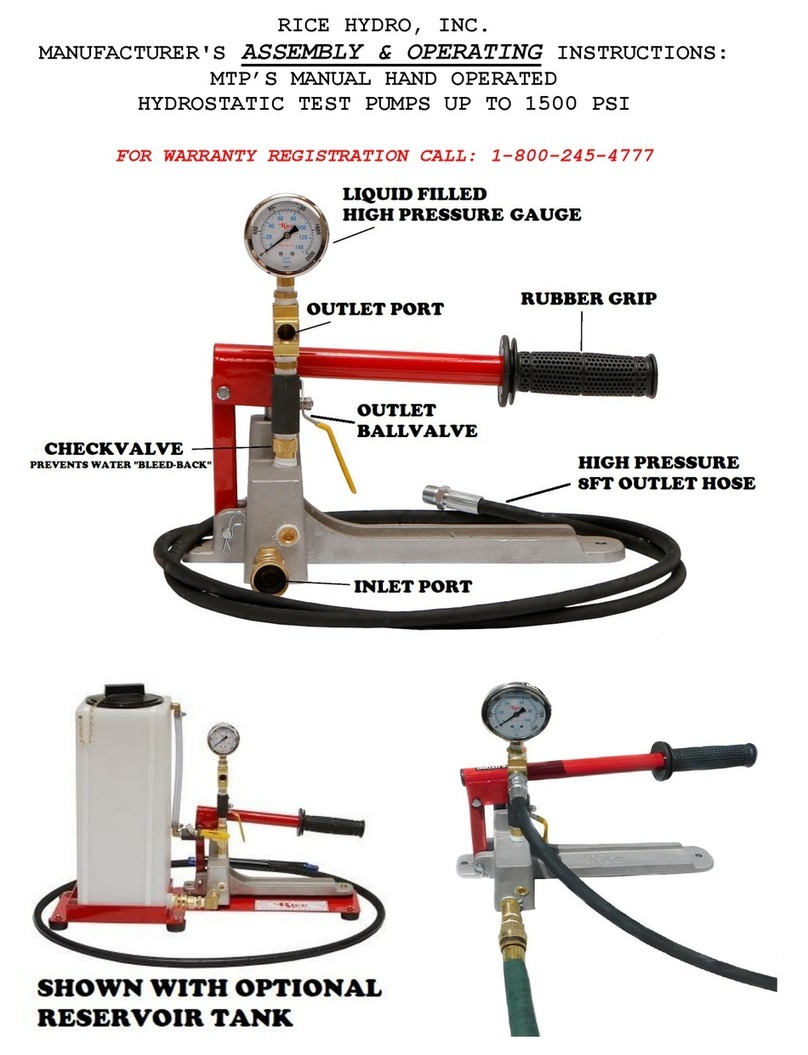
MANUFACTURER'S OPERATING INSTRUCTIONS
EL-SERIES MODEL TEST PUMPS
FOR WARRANTY REGISTRATION CALL: 1-800-245-4777
WARNING: Operating, servicing and maintaining this equipment can expose you to chemicals including engine exhaust, carbon monoxide and
lead, which are known to the State of California to cause cancer and birth defects or other reproductive harm. To minimize exposure, avoid
breathing exhaust, do not idle the engine except as necessary, operate and service your equipment in a well-ventilated area and wear gloves
or wash your hands frequently when servicing your equipment. For more information go to: www.p65warnings.ca.gov
CAUTIONS:
1.
Power source must meet voltage, phase, hertz and amperage requirements of
electric motor, as stated on label. If an extension cord is used, requires at
least 12 gauge 3 wire with maximum of 25 foot length.
2.
Check ALL fluid levels prior to operating the unit.
3. Use a sound 3/4" or larger supply hose.
4. Protect the pump from freezing, FLUSH with anti-freeze.
5. DO NOT run dry or pump chlorine thru the unit.
CONNECTING THE PUMP:
1.
With motor switch in the off position, connect power cord of motor to a standard
wall outlet. Extension cord: when needed, requires a 12 gauge 3 wire, maximum
25 foot length plugged into a 20 or larger amp breaker, depending on individual
motor requirements.
2.
Connect CLEAN pressurized water source to the inlet of the pump. It is
recommended that the unit be pressure fed. For gravity feed locate water within
8 feet and elevated above level of unit, and then prime the pump.
3.
Connect high-pressure outlet hose to the pump and your test environment.
OPERATING THE PUMP:
1.
Turn the outlet ballvalve to the open position, start the motor.
2.
The pressure regulator has been preset at the factory. To change this setting
you must make this adjustment while the water is flowing freely, and the unit is
under NO pressure. To adjust the pressure, first loosen the locknut. Turn the T-
handle/Knob clockwise to increase and counter-clockwise to decrease the
pressure. Place a ballvalve or similar open and close valve at the end of the
outlet hose, open and close this valve multiple times as needed, to check
pressure setting and re-adjust as necessary. It is also recommended that you
open and close the hosebib located under the gauge to bleed excess air from
piping and ensure accurate pressure gauge readings. Upon reaching desired
pressure setting, tighten locknut and prepare to begin test.
3.
With the ballvalve open begin building pressure in the test environment. Be
sure to bleed the air from hosebib under gauge at least once during this
process. Once test pressure has been reached, close the ballvalve and shut-off
motor. An inlet checkvalve prevents water pressure from bleeding back into the
pump.
4.
Once the outlet ballvalve is closed and your test begins, you have now isolated
the test pump from the test environment, any loss of pressure is due to leaks or
trapped air being compressed in the test environment.
RECOMMENDED MAINTENANCE
1.
Pumps use non-detergent 30wt oil, gear reductions use 90wt gear oil.

Part # Description Qty
0006.09 BUSHING D45X52X16 HK45-16 1
0007.18 OIL SEAL D15X24X4 3
0007.24 OIL SEAL D40X52X7 1
0009.09 ELASTIC RING D52X2.5 1
0014.20 PLUNGER GUIDE D15/18 “PN” 3
0021.15 WATER SEAL LP. D15 BE3
0023.22 RING D6.3X9X1.3 2021 “PN/C/G” CE3
0023.25 INTERMEDIATE RING D15 “PN” 3
0031.42
HOLLOW SHAFT “PN” D5/8”
1
0103.41 CONNECTING ROD “PN/PS” 3
0208.70 COVER “PN” 1
0208.72 BACK COVER “PN” 1
0209.56 CRANKCASE “PN/PS” 1
0214.21 BALL BEARING D20X52X15 1
0301.42 SLINGER RING “PN/PK/PKWT/PS” D3
0303.18 NUT “PN/PK/PKWT/PS M8XH5 D3
0517.08 ENGINE FLANGE “PN” NEMA 56H 1
0602.76 BACK COVER GASKET “PN/PK/PW/PS 1
0605.09 GASKET D17X23X1.5 (G3/8) 1
0605.33 GASKET D8X14X2 D3
0605.49 GASKET D13X19X1.5 1
0635.01 HIGH PRESS. SEAL ASSY D15 BE3
1101.A2 O-RING - VALVE CAP E6
1101.A3 O-RING - VALVE A E 6
1101.A4 O-RING - PLUNGER D3
1101.A6 O-RING - BEARING COVER 1
Part # Description Qty
1101.A7 O-RING - LP SEAL RETAINER B C E 3
1205.35 CERAMIC PLUNGER D15X30 “PN” 3
1212.10 METAL COVER “PN” 1
1221.11 LOW PRESS. SEAL RETAINER D15 CE3
1411.01 SERATED WASHER D6 12
1502.15 PIN D7X25.5 3
1506.26 SNAP RING D20 1
1603.64 PLUG G3/8 1
1603.67 PLUG G1/4 1
1603.69 OIL PLUG G1/4+GASKET 1
1603.72 VALVE PLUG “PN”PISTON D15/18 E6
1604.59 HEAD “PN” PISTON D15/18 E1
1625.10 OIL PLUG G3/8 “PN” 1
1805.19 ALLEN BOLT M6X25 4
1805.20 ALLEN BOLT M6X16 8
1805.39 ALLEN BOLT M6X60 8
6006.25 VALVE ASSY “PN” W/O O-RING AE6
6017.20 COMPLETE MANIFOLD ASSEMBLY 1
6061.01 KIT 1 - VALVE KIT “PN/PW” 1
6061.07 KIT 7 - WATER SEAL KIT D15 “PN/PK” 1
6061.13 KIT 13 - BRASS RING KIT D15 “PN” 1
6061.20 Kit 20 - PLUNGER KIT D15/18 “PN” 1
A
B
C
D
E
Parts in 6061.01 (Kit 1).
Parts in 6061.07 (Kit 7).
Parts in 6061.13 (Kit 13).
Parts in 6061.20 (Kit 20).
Parts in 6017.20 (Complete Manifold Assembly).
-
PNL 3.0/20-Z
MAX FLOW 3.0 GPM 11 L/MIN
MAX PRESSURE 2000 PSI / 130 BAR
RATED PUMP SPEED 3400 RPM
POWER REQUIREMENT 4.0 HP ELECTRIC
LUBRICATION 14 OZ UDOR LUBE

WEIGHT 13 LBS
LUBRICATION 10 OZ UDOR LUBE
PN SERIES DIMENSIONS
Dimensional Drawings are
Shown in Millimeters.
To Convert to Inches,
Multiply Dimension x 0.03937
PN SERIES PUMPS - 5/8” HOLLOW SHAFT w/ NEMA 56C FLANGE
TORQUE SPECS
Ref. Description Ft./lb. Nm Loctite®
1
Head Bolts
8 11 -
2 Valve Caps 75 100 243
3 Inlet Cap 60 80 -
4 Outlet Cap 60 80 243
5 Bearing Flange Bolts 8 11 -
6 Rear Cover Bolts 8 11 -
7 Connecting Rod Bolts - - -
8 Plunger Bolts 11 15 270
9 Valve Cover Bolts - - -
10 Oil Drain Plug 6 8 -

QTY
PART NUMBER.. DESCRIPTION.. REQ'D
UDO4-0006.09 BEARING 1
UD04-0007.18 SEAL 3
UD04-0007.24 SEAL 1
UD04-0009.09 RETAINER CLIP 1
UD04-0014.20 PLUNGER ROD 3
UD04-0021.15 WATER SEAL 3
UD04-0023.22 SUPPORT RING 1
UD04-0031.42 CRANKSHAFT 1
UD04-0103.41 ALUMINUM CONNECTING ROD 3
UD04-0208.70 BACK COVER 1
UD04-0208.72 CRANKCASE COVER 1
UD04-0209.56 CRANKCASE 1
UD04-0214.21 BEARING 1
UD04-0301.42 SLINGER RING 1
UD04-0303.18 PLUNGER NUT 1
UD04-0517.08 ELECTRIC FLANGE 1
UD04-0602.76 GASKET - CRANKCASE COVER 1
UD02-0605.09 ALUMINUM WASHER 1
UD04-0605.33 PLUNGER WASHER 1
UD04-0605.49 O-RING 1
UD04-0635.01 HIGH PRESSURE SEAL ASSY 3
UD04-1101.A2 O-RING 6
UD04-1101.A3 VALVE O-RING 6
UD04-1101.A4 O-RING 1
UD04-1101.A6 O-RING 1
UD04-1101.A7 O-RING 3
UDO4-1205.35 PLUNGER - 15 MM 3
UD04-1212.10 SIDE PLATE 1
UD04-1221.11 LOW PRESSURE SEAL RETAINER 3
UD04-1411.01 WASHER 12
UD04-1502.15 CONNECTING ROD PIN 3
UD04-1506.26 SNAP RING 1
UD04-1603.64 3/8" PLUG 1
UD02-1603.67 DRAIN PLUG 1
UDO4-1603.69 SIGHT GLASS 1
UD04-1603.72 VALVE CAP 6
UD04-1604.59 BRASS MANIFOLD 1
UD04-1625.10 OIL PLUG 1
UD04-1805.19 BOLT 4
UD04-1805.20 BOLT 8
UD04-1805.39 BOLT 8
UD04-6006.25 VALVE ASSY KIT w/o O-RING 6
OUTLET HOSES:
HOSE-3/8X8-RH 8' FOOT OUTLET HOSE - STANDARD 1
COUPLERBODY-BR-3/8F FEMALE PUMP OUTLET - HOSE 1
COUPLERPLUG-3/8M MALE PUMP OUTLET - PIPING 1
HOSE-3/8-3000XFT SPECIFY LENGTH OF HOSE
FITTING-3/8-MPIPE FITTING FOR HOSE - RIGID 1
FITTING-3/8-MPX FITTING FOR HOSE - SWIVEL 1
MOTORS & PUMPS:
MOTOR-1HP-CFACE (EL2) 1HP 110/220V 1 PHASE 50/60HZ 1
MOTOR-1.5HP-50/60HZ (EL3) 1.5HP 110/220V 1 PHASE 50/60HZ 1
SPEC-PNL-3.0/20-Z TRIPLEX PLUNGER PUMP 1
PAGE 1 OF 2
PARTS BREAKDOWN FOR MODELS: EL2, EL3
RICE HYDRO INC.

QTY
PART NUMBER.. DESCRIPTION.. REQ'D
MISCELLANEOUS PARTS:
HOSESWIVEL-1/2 HOSE SWIVEL INLET 1
HOSESCREEN&WASHER INLET HOSE SCREEN 1
BALLVALVE-3/8HP OUTLET BALLVALVE 1
VALVE-RELIEF-900PSI (EL2) PRESSURE REGULATOR 1
RED SPRING 100-900 PSI
VALVE-RELIEF-2000PSI (EL3) PRESSURE REGULATOR 1
YELLOW SPRING 200-2000 PSI
GAUGE-1500 (EL2) 0-1500 PSI LIQUID GAUGE 1
GAUGE-2000 (EL3) 0-2000 PSI LIQUID GAUGE 1
NEEDLEVALVE-1/4 AIR BLEED VALVE 1
KING-EL1A SHIPPING BOX 1
LABEL-KIT-EL INSTRUCTION AND CAUTION STICKERS 1
KITS: *Kits are all inclusive
UD04-6061.01 VALVE KIT
UD04-6061.07 SEAL KIT
UD04-6061.13 BRASS KIT
UDO4-6061.20 PLUNGER O-RING KIT
PAGE 2 OF 2
RICE HYDRO INC.
PARTS BREAKDOWN FOR MODELS: EL2, EL3
This manual suits for next models
6
Table of contents
Other RICE HYDRO Water Pump manuals
Popular Water Pump manuals by other brands

Jula
Jula 731-075 operating instructions

Tsurumi Pump
Tsurumi Pump KTD Series Operation manual

WillowWood
WillowWood LimbLogic Patient Instructions For Use

Viking pump
Viking pump 1224A-CHC Series Installation operation & maintenance

BLACKMER
BLACKMER X1220A Installation, operation and maintenance instructions

Whale
Whale BP0527 quick start guide

Grundfos
Grundfos NB instructions

Xylem
Xylem Bell & Gossett 1510 Series instruction manual

HALE
HALE FOAM MASTER 3.3 Description, Installation and Operation Manual

Oase
Oase Aquarius Universal 4000 operating instructions

LMI
LMI ROYTRONIC A Series instruction manual

Wilo
Wilo HiMulti 3 P Series Installation and operating instructions