RiddledTV JAMMA User manual

RiddledTV.com Page 1 Rev. 10-16-2017
RiddledTV.com 2-Way JAMMA Switcher
INSTALLATION GUIDE
Figure 1. 2-Way JAMMA Switcher Kit
Each Kit Includes:
2-way Mainboard
Features:
Supports 2 JAMMA boards
Only 1 JAMMA board is powered at a time.
No external remotes are required
Games are switched by holding Player1-Start and Player2-Start for 1.5 seconds, or alternate
buttons can be connected.
Supports 6 button inputs per player
Supports up to 20 Amps on 5V
-5V power is switched for each board

RiddledTV.com Page 2 Rev. 10-16-2017
Mainboard Components:
Figure 2 –2-Way Switcher with Indicator Arrows
A. JAMMA port for Gameboard #1
B. JAMMA port for Gameboard #2
C. Indicator light that Gameboard #1 is active
D. Indicator light that Gameboard #2 is active
E. Game Select Button Inputs. If jumpers are installed as shown, players 1 and 2 start buttons (held
for 1.5 sec) will switch to the next game.
F. 3 Relays for switching of Speaker, 5V, 12V, -5V
G. Power indicator LEDs. 12V, 5V, -5V (these only indicate presence of voltage, not accuracy of
voltage levels)
H. Selector for JAMMA pins e and 27 on Gameboard #2
I. Selector for JAMMA pins e and 27 on Gameboard #1
J. Indicator lights that illuminate when 1 or both of the game select button inputs are active.
K. JAMMA harness input from control panel, monitor, speaker, and power supply

RiddledTV.com Page 3 Rev. 10-16-2017
JAMMA Switcher Pinouts
Solder Side
Parts Side
GROUND
A
1
GROUND
GROUND
B
2
GROUND
+5VDC
C
3
+5VDC
+5VDC
D
4
+5VDC
-5VDC
E
5
-5VDC
+12VDC
F
6
+12VDC
KEY SLOT
H
7
KEY SLOT
COUNTER #2 (N/C)
J
8
COUNTER #1 (N/C)
COIL #2 (N/C)
K
9
COIL #1 (N/C)
SPEAKER (-)
L
10
SPEAKER (+)
UNDEFINED
M
11
UNDEFINED
VIDEO GREEN
N
12
VIDEO RED
VIDEO SYNC
P
13
VIDEO BLUE
SERVICE SWITCH
R
14
VIDEO GROUND
TILT (SLAM) SWITCH
S
15
TEST SWITCH
COIN SWITCH #2
T
16
COIN SWITCH #1
PLAYER 2 - START
U
17
PLAYER 1 - START
PLAYER 2 - UP
V
18
PLAYER 1 - UP
PLAYER 2 - DOWN
W
19
PLAYER 1 - DOWN
PLAYER 2 - LEFT
X
20
PLAYER 1 - LEFT
PLAYER 2 - RIGHT
Y
21
PLAYER 1 - RIGHT
PLAYER 2 - BUTTON 1
Z
22
PLAYER 1 - BUTTON 1
PLAYER 2 - BUTTON 2
a
23
PLAYER 1 - BUTTON 2
PLAYER 2 - BUTTON 3
b
24
PLAYER 1 - BUTTON 3
PLAYER 2 - BUTTON 4
c
25
PLAYER 1 - BUTTON 4
PLAYER 2 - BUTTON 5
d
26
PLAYER 1 - BUTTON 5
PLAYER 2 - BUTTON 6/GND
e
27
PLAYER 1 - BUTTON 6/GND
GROUND
f
28
GROUND
Figure 3. JAMMA Switcher Pinouts

RiddledTV.com Page 4 Rev. 10-16-2017
Installation Instructions:
1. Disconnect AC power.
2. Verify your JAMMA harness wiring matches the standard as shown in Figure 3.
3. Plug the Switcher into your existing JAMMA harness and mount in a suitable location.
Note: Do NOT connect the JAMMA gameboards yet.
4. Double-check all your work.
5. Reconnect AC power, and turn the power on.
6. Verify that the switcher is receiving inputs from your control panel by doing the following:
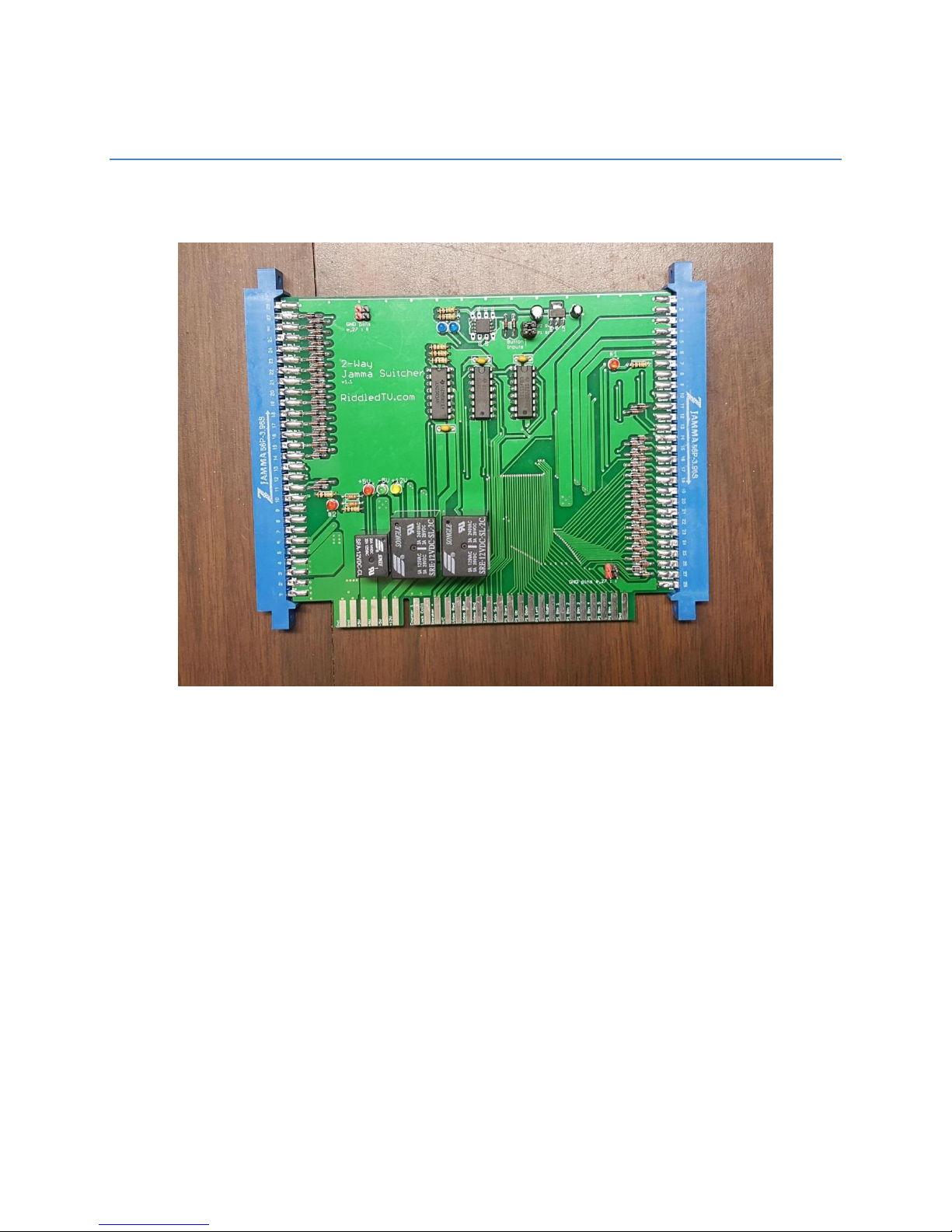
a. Press Player1-Start. Verify that the 1st Blue LED on the switcher circuit board illuminates
as the Player1-Start button is pressed. Note, If an alternate input button is being used,
verify the input from that button in place of Player1-Start.
b. Press Player2-Start. Verify that the 2nd Blue LED on the switcher circuit board
illuminates as the Player2-Start button is pressed. Note, If an alternate input button is
being used, verify the input from that button in place of Player2-Start.
7. Turn power switches off, and disconnect AC power
8. Plug the JAMMA gameboards into the right and left side of the JAMMA Switcher. Make
certain that all boards are securely mounted and are not contacting other wiring or metal
supports inside your arcade cabinet
9. Reconnect AC power, and turn the power on
10. To advance to the next game hold down both Player1-Start and Player2-Start buttons.
11. You may need to readjust your monitor’s color balance levels.
(The remainder of this page intentionally left blank)

RiddledTV.com Page 5 Rev. 10-16-2017
Switching Games:
If both jumpers are installed as shown, the mainboard will switch games when buttons Player 1-Start
and Player 2-Start are pressed for 1.5 seconds. To use alternate button inputs, disconnect the 2
jumpers, and connect two button inputs of your choice to the two terminals on the left side, above the
arrow as shown in Figure 4. If only one input button is desired, connect it to BOTH pins. The Switcher
will change games when both inputs are grounded for 1.5 seconds. If both buttons are held down, it
will continue to cycle between games in 1.5 second increments.
Figure 4. Button Inputs for Game Selection
Indicator lights
The mainboard has 7 indicator LED lights:
2 Red LEDs to indicate which gameboard is active
3 Power Supply indicator LEDs. Red, Green, and Yellow LEDs indicate that “some” voltage is
present on the 5V, -5V, and 12V power supplies. They do not indicate the accuracy of those
voltages.
2 Blue LEDs indicate that the switcher detects one or both of the game-select buttons are
pressed.

RiddledTV.com Page 6 Rev. 10-16-2017
Grounding of JAMMA pins 27, e:
Refer to the Figure 3 for JAMMA pinouts. The initial JAMMA standard indicated that these pins were
signal grounds. However, many gameboards have repurposed these pins for button inputs. To use pins
“27” and “e” as button inputs, leave the pins vacant, as shown in Figure 5 below. To modify these pins
to be grounded, apply jumpers (also commonly referred to as shunts). To jumper, the two red pins
should be connected together, and the two black pins as well. This option should be configured for each
gameboard uniquely.
Figure 5. JAMMA Pins “27” and “e” Selection
Monitor Synchronization:
The Switcher will work best with an "auto-sync" (multi-sync) type game monitor. These were common
in monitors made after 1994, but there were also auto-sync monitors made before that time. It is
possible to use the Switcher on an older manual-sync monitor, but depending on your game boards the
display on some games could "roll" or not sync without manually tweaking the monitor controls when
you switch games.
You may be able to set an older manual-sync monitor to a setting that will sync for both games through
trial and error. The success will depend upon the monitor and specific games used.

RiddledTV.com Page 7 Rev. 10-16-2017
Troubleshooting:
My controls are not responding –JAMMA harness Ground wires fed from pins 27 & e of the
gameboard: Several instances have been found where the JAMMA harness wiring uses pins 27, e as a
grounding takeoff point for the control panel wiring. If your harness does this, the Switcher will not
respond to any inputs from the control panel. The workaround for this: connect a wire from your GND
on your power supply to the GND on your control panel. In most instances only a single wire will be
needed. In some rare instances an additional 2nd GND wire for Player2 is also needed.
Table of contents