micro CA-300 Inspection Camera
3
Safety Symbols
In this operator’s manual and on the product, safety symbols and signal words are used to
communicate important safety information. This section is provided to improve understand-
ing of these signal words and symbols.
This is the safety alert symbol. It is used to alert you to potential personal injury hazards.
Obey all safety messages that follow this symbol to avoid possible injury or death.
DANGER
WARNING
CAUTION
NOTICE
DANGER indicates a hazardous situation which, if not avoided, will result in death
or serious injury.
WARNING indicates a hazardous situation which, if not avoided, could result in
death or serious injury.
CAUTION indicates a hazardous situation which, if not avoided, could result in mi-
nor or moderate injury.
NOTICE indicates information that relates to the protection of property.
This symbol means read the operator’s manual carefully before using the equipment.
The operator’s manual contains important information on the safe and proper operation
of the equipment.
This symbol means always wear safety glasses with side shields or goggles when han-
dling or using this equipment to reduce the risk of eye injury.
This symbol indicates the risk of hands, ngers or other body parts being caught or
wrapped in gears or other moving parts.
This symbol indicates the risk of electrical shock.
General Safety
Information
WARNING
Read all safety warnings and instructions.
Failure to follow the warnings and instruc‑
tions may result in electric shock, fire and/
or serious injury.
SAVE THESE INSTRUCTIONS!
Work Area Safety
Keep your work area clean and well
lit. Cluttered or dark areas invite acci-
dents.
Donotoperateequipmentinexplosive
atmospheres, such as in the presence
of ammable liquids, gases or dust.
Equipment can create sparks which may
ignite the dust or fumes.
Keep children and by-standers away
while operating equipment. Distrac-
tions can cause you to lose control.
Electrical Safety
Avoid body contact with earthed or
groundedsurfacessuchas pipes,radi-
ators, ranges and refrigerators. There
is an increased risk of electrical shock if
your body is earthed or grounded.
Do not expose equipment to rain or
wet conditions. Water entering equip-
ment will increase the risk of electrical
shock.
Personal Safety
Stay alert, watch what you are doing
and use common sense when oper-
ating equipment. Do not use equip-
ment while you are tired or under
the inuence of drugs, alcohol or
medication. A moment of inattention
while operating equipment may result
in serious personal injury.
Do not overreach. Keep proper foot-
ing and balance at all times. This en-
ables better control of the power tool
in unexpected situations.
Contents
Safety Symbols.................................................................................................................................................3
General Safety Information.......................................................................................................................3
Work Area Safety........................................................................................................................................... 3
Electrical Safety ............................................................................................................................................. 3
Personal Safety .............................................................................................................................................. 3
Equipment Use and Care...........................................................................................................................4
Service............................................................................................................................................................... 4
Specic Safety Information....................................................................................................................... 4
micro CA-300 Inspection Camera Safety............................................................................................4
Description, Specications and Standard Equipment ............................................................... 5
Description......................................................................................................................................................5
Specications................................................................................................................................................. 5
Standard Equipment................................................................................................................................... 6
Controls ............................................................................................................................................................6
FCC Statement.................................................................................................................................................. 6
Electromagnetic Compatibility (EMC).................................................................................................7
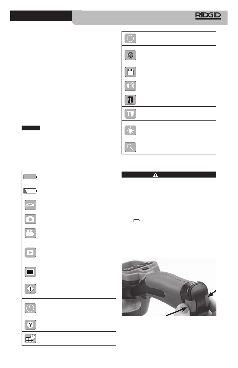
Icons....................................................................................................................................................................... 7
Tool Assembly................................................................................................................................................... 7
Changing/Installing Batteries.................................................................................................................. 7
Powering with the AC Adapter ..............................................................................................................8
Installing the Imager Head Cable or Extension Cables ................................................................ 8
Installing Accessories.................................................................................................................................. 8
Installing SD™ Card......................................................................................................................................8
Pre-Operation Inspection .......................................................................................................................... 9
Tool and Work Area Set-Up........................................................................................................................9
Operating Instructions ..............................................................................................................................10
Live Screen ....................................................................................................................................................11
Image Adjustment ....................................................................................................................................11
Image Capture.............................................................................................................................................12
Menu................................................................................................................................................................12
Time Stamp...................................................................................................................................................13
Image Quality...............................................................................................................................................13
Video Quality................................................................................................................................................13
Language ......................................................................................................................................................13
Date/Time .....................................................................................................................................................13
TV-Out ............................................................................................................................................................13
Storage ...........................................................................................................................................................13
Speaker ..........................................................................................................................................................13
Auto Power O ...........................................................................................................................................13
Factory Reset ...............................................................................................................................................13
About ..............................................................................................................................................................13
Transferring Images to a Computer....................................................................................................13
Connecting to TV........................................................................................................................................14
Using with SeeSnake®Inspection Equipment.................................................................................14
Maintenance....................................................................................................................................................15
Reset Function.............................................................................................................................................15
Accessories.......................................................................................................................................................15
Storage...............................................................................................................................................................15
Service and Repair........................................................................................................................................15
Disposal..............................................................................................................................................................15
Troubleshooting............................................................................................................................................16
Battery Pack/Battery Charger Safety.................................................................................................16
Description and Specications..............................................................................................................17
Charger Inspection and Set-Up.............................................................................................................17
Charging Procedure/Operating Instructions.................................................................................18
Cleaning Instructions .................................................................................................................................18
Accessories.......................................................................................................................................................19
Storage...............................................................................................................................................................19
Service and Repair........................................................................................................................................19
Disposal..............................................................................................................................................................19