3
SuperFreeze®Pipe Freezing Units
•Do not overreach. Keep proper footing and balance
at all times. This enables better control of the power
tool in unexpected situations.
Tool Use and Care
•Do not force the tool. Use the correct tool for your
application. The correct tool will do the job better
and safer at the rate for which it is designed.
•Do not use tool if the switch does not turn it ON
and OFF. Any tool that cannot be controlled with the
switch is dangerous and must be repaired.
•Disconnect the plug from the power source before
making any adjustments, changing accessories, or
storing the tool. Such preventive safety measures
reduce the risk of starting the tool accidentally.
•Store idle tools out of the reach of children and
other untrained persons. Tools are dangerous in
the hands of untrained users.
•Maintain the tools. Check for misalignment or bind-
ing of moving parts, breakage of parts and any
other condition that may affect the tool’s operation.
If damaged, have the tool repaired before use.
Many accidents are caused by poorly maintained tools.
•Use only accessories that are recommended by
the manufacturer for your model. Accessories that
may be suitable for one tool, may become hazardous
when used on another tool.
Service
•Have your tool serviced by a qualified repair per-
son using only identical replacement parts. This will
ensure that the safety of the tool is maintained.
Pipe Freezing Unit Safety
Warnings
WARNING
This section contains important safety information
that is specific to this tool.
Read these precautions carefully before using the
SuperFreeze units to reduce the risk of electri-
cal shock or other serious injury.
SAVE THESE INSTRUCTIONS!
The SuperFreeze®units include space in the unit to keep
this manual with machine for use by the operator.
•This tool is used to freeze a water plug inside
copper, steel or other thermally conductive metal-
lic tubes or pipes. Do not use on plastic pipe or
tube. Follow instructions on proper use. Other uses
may increase the risk of injury.
•Do not touch the freeze heads while frosted. Touch-
ing the freeze heads while frosted can cause frostbite.
Wear gloves if handling during use.
•Before opening piping system, test to confirm
that the ice plugs are fully formed and stable.
Opening the piping system before a complete plug is
frozen or allowing the plug to thaw while the system is
open could cause burns, electric shock or other serious
injury or result in flooding or other property damage.
•Do not twist, kink or pull hoses. Do not open
refrigerant piping. This can lead to refrigerant leaks
and cause frostbite, asphyxiation and other serious
injury. If a leak occurs, leave the area until the refrig-
erant dissipates.
The EC Declaration of Conformity (890-011-320.10) will
accompany this manual as a separate booklet when
required.
If you have any question concerning this RIDGID®product:
– Contact your local RIDGID distributor.
– Visit www.RIDGID.com or www.RIDGID.eu to find
your local RIDGID contact point.
– Contact Ridge Tool Technical Service Department at
Canada call (800) 519-3456.
Description, Specifications and
Standard Equipment
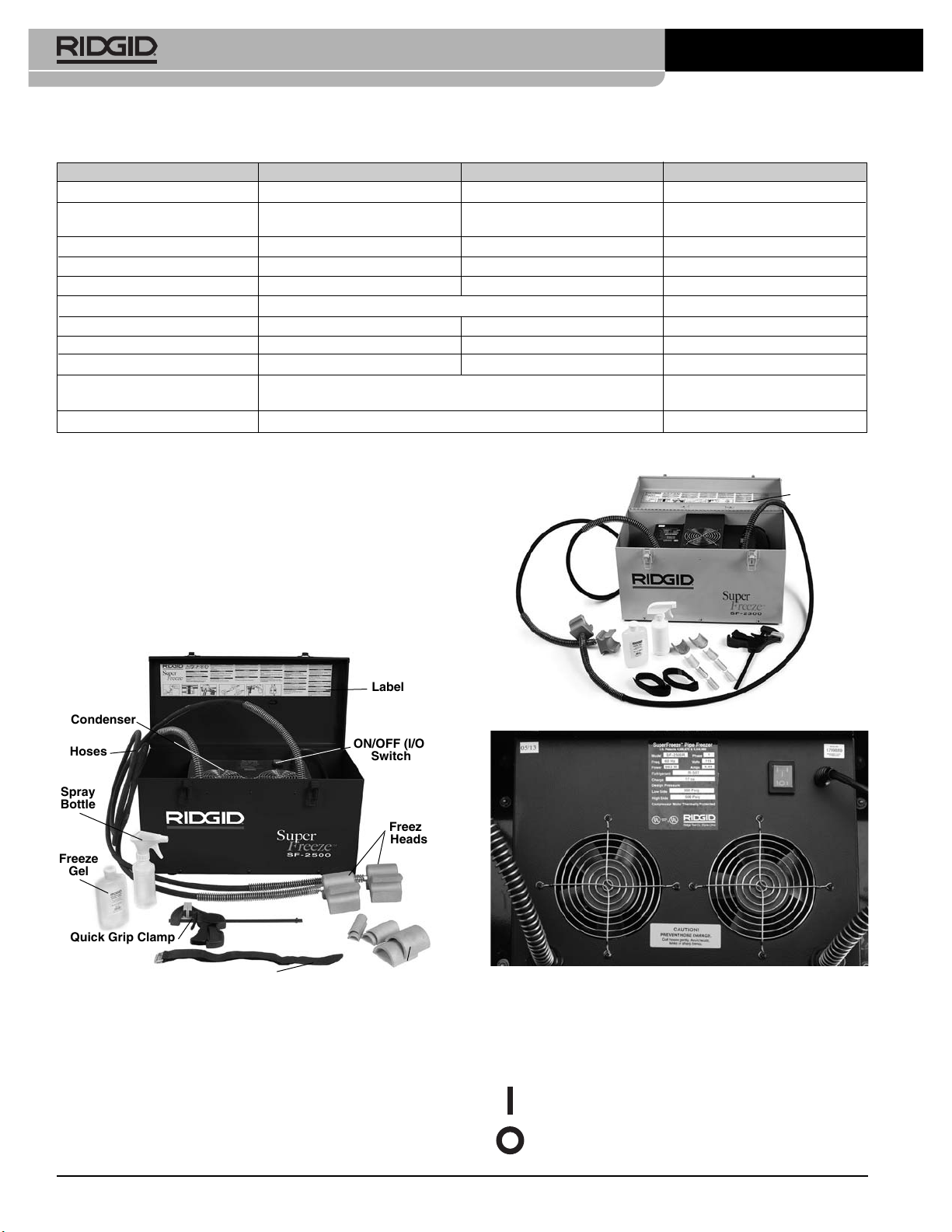
Description
The RIDGID®SuperFreeze®Pipe Freezing Units are used
to freeze plugs in water piping systems to allow mainte-
nance without shutting down or draining the system. The
units are self-contained refrigeration units that circulate
refrigerant to the aluminum freeze heads. The freeze
heads, attached to the piping system, can freeze a plug in
metallic tubing or pipes. Once the work is complete, the
SuperFreeze unit is turned OFF and the ice plugs melt,
returning the system to operation.
The SuperFreeze units do not use CO2or Nitrogen, and do
not require the release of refrigerants. They use specially
designed compressors with overload protection. The SF-
2500 also includes quick restart capabilities. The freeze
head hoses are leak free flexible rubber. The units are
enclosed in a portable carry case.