RIEJU Century 125 Instruction manual

CENTURY 125 i.e E4
Engine Workshop Manual

Engine
Workshop Manual
Century 125i.e.
ENGLISH
The descriptions and images in this publication are given for illustrative purposes only and are not binding.
While the basic characteristics as described and illustrated in this booklet remain unchanged, Rieju S.A.
reserves the right, at any time and without being required to update this publication beforehand, to make
any changes to components, parts or accessories, which it considers necessary to improve the product
or which are required for manufacturing or construction reasons.
Not all versions/models shown in this publication are available in all countries. The availability of each
model should be checked at the official RIEJU sales network.
© Copyright 2014 - Rieju S.A. All rights reserved. Reproduction of this publication in whole or in part is
prohibited.
Rieju S.A. C/ Borrassà 41 E-17600 Figueres GIRONA-SPAIN
www.riejumoto.com

ENGINE WORKSHOP MANUAL
Century 125 i.e.
ENGLISH
This manual for service stations was made by Rieju S.A. to be used by the workshops of dealers and
sub-agencies RIEJU. It is assumed that users of this publication for the maintenance and repair of
Rieju vehicles has a basic knowledge of the principles of mechanics and technique procedures of
vehicle repair. Any significant changes to vehicle characteristics or specific repair operations will be
communicated by updates to this manual.
N.B. Provides key information to make the procedure easier to understand and carry out.
CAUTION Refers to specific procedures to carry out for preventing damages to the vehicle.
WARNING Refers to specific procedures to carry out to prevent injuries to the repairer.
Personal safety Failure to completely observe these instructions will result in serious risk of personal
injury.
Safeguarding the environment Sections marked with this symbol indicate the correct use of the vehicle
to prevent damaging the environment.
Vehicle intactness The incomplete or non-observance of these regulations leads to the risk of serious
damage to the vehicle and sometimes even the invalidity of the guarantee.

6
8
14
19
21
23
32
36
43
1. GEARBOX
2. STARTER MOTOR
3. GENERATOR SIDE
4. CLUTCH SIDE
a. Checking the clutch
b. Cheecking the springs
5. CRANKCASE
a. Bushing slection
6. HEAD AND TIMING
a. Checking the overhead camshaft
6.
9
ENGLISH
Index
43
46
52
54
59
9. LUBRICATION
c. Valve clerance
b. Valve check
d.
e.Checking the connecting rod small end
b. Valve check
c. Valve clerance
b. Valve check
c. Checking the piston

Engine
ENGLISH
5

Engine
6
ENGLISH
Gearbox
Gearbox shafts
Disassembling the gearbox
•Open the crankcase halves.
•Remove the gaskets from the crank-
case.
•Take out both fork rods and the trans-
mission forks (1) (2).
•Take out the desmodromic control (3).
•Take out the secondary axle (4).
•Take out the primary axle (5).
See also
Crankcase opening
Checking the primary shaft
COUPLING CLASSES
The gears of the primary drive are classified according to the coupling with the gear of the clutch housing
and with the gear of the balancing countershaft and follow the logic shown in the tables listed below:
COUPLING CLASSES CLUTCH HOUSING - FIRST GEAR SHAFT
Coupling classes on Crankcase Clutch housing gear Transmission gear
X X X
Y Y Y
COUPLING CLASSES FIRST GEAR SHAFT - BALANCING COUNTERSHAFT
Coupling classes on Crankcase Transmission gear Balancing countershaft gear
S S S
T T T
NOTE

ENGLISH
Engine
7
THE CLASS AS WELL AS BEING REPRODUCED ON TWO COUPLING ELEMENTS IS ALSO
SHOWN ON THE TWO CRANKCASE HALVES OF THE CRANKCASE.
NOTE
CRANKCASE SPARE PARTS ARE ALWAYS CLASS X.
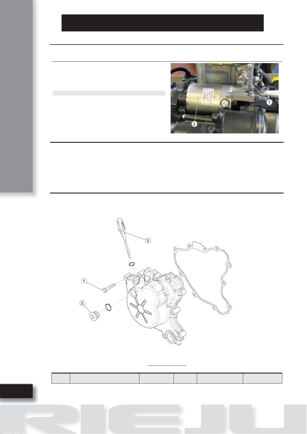
Checking the desmodromic drum
•Check the contact zone on fork (1) and the driving pin (2) of the forks for wear.
•Check the desmodromic drum (4) grooves (3) for wear.
•Make sure that both ball bearings rotate freely and check if there are signs of corrosion.
•Check the eccentricity of the transmis-
sion shafts.
•Check the condition of the two springs
(5) and (6) of the selector (7).
•Check the condition of the gears, re-
place them if they are blue, if they have
cracks or are worn.
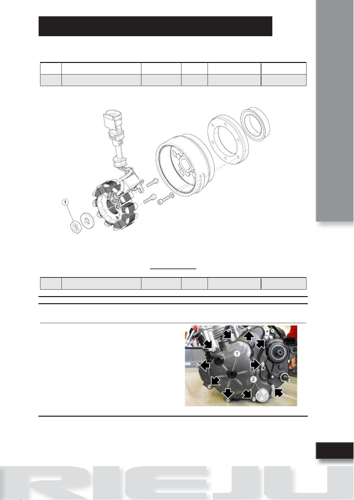
Assembling the gearbox
•Place the specific tool on the secon-
dary shaft to avoid damaging the oil
seal.
•Heat up the engine crankcase.
•Apply LOCTITE Anti-Seize on the
bearing seats present on the crank-
case.
•Fit the bearings in their seats.
•Insert the gears unit (5).
•Apply oil for gears on the grooves of the desmodromic drum.

Engine
8
ENGLISH
•Position the desmodromic drum in the crankcase (3).
•Fit the two axles of the transmission forks (1)(2).
•Fit the two transmission forks.
•Finally, fit the crankshaft.
Starter motor
STARTER MOTOR
pos. Description Type Quantity Torque Notes
1 Starter motor fixing screw M6x25 2 11 - 13 Nm (8.11 - 9.58
lbf ft)
-
STARTER MOTOR
•Make sure that the toothing (1) is not
deformed or worn.
•Make sure that the O-ring (2) is not
damaged or worn.
•The electric starter motor is not fitted
for repair. If necessary, replace the
whole motor.

ENGLISH
Engine
9
Removing the starter motor
•Undo and remove the two fixing screws
(1).
•Remove the starter motor (2).
NOTE
THE STARTER MOTOR CAN ALSO BE REMOVED IF THE
ENGINE IS FITTED TO THE VEHICLE.
Installing the starter motor
•Place the electric starter motor.
•Apply LOCTITE 221.
•Tighten the starter motor fixing screws.
Generator side
FLYWHEEL COVER
pos. Description Type Quantity Torque Notes
1 Flywheel cover fastener screw M6 10 11 - 13 Nm (8.11 - 9.58
lbf ft)
-

Engine
10
ENGLISH
pos. Description Type Quantity Torque Notes
2 Timing control cover M18 2 3.5 - 4.5 Nm (2.58 - 3.31
lbf ft)
-
3 Oil dipstick M12x1.5 1 4 - 6 Nm (2.95 - 4.42 lbf
ft)
-
IGNITION UNIT
pos. Description Type Quantity Torque Notes
1 Flywheel rotor fixing screw M14x1.5 1 83 - 90 Nm (61.21 -
66.38 lb ft)
-
Removing the flywheel cover
•Unscrew and remove the two adjust-
ment plugs (1).
•Unscrew and remove the engine oil
pre-filter plug (2).
•Remove the engine oil pre-filter.
•Undo and remove the ten screws fixing
the flywheel cover.
•Remove the flywheel cover.

ENGLISH
Engine
11
Magneto flywheel removal
•Remove the starter motor gear.
•Position the locking tool.
•Unscrew and remove the hex head
screw and retrieve the washer.
•Position the tool.
•Remove the flywheel and its spline.

Engine
12
ENGLISH
•Remove the oil filter.

ENGLISH
Engine
13
Freewheel removal
•Undo and remove the screw from the
lock.
•Remove the freewheel.
Installing the flywheel
For refitting follow the operations described previously in reverse order.
See also
Magneto flywheel removal

Motor
14
ENGLISH
Clutch side
CLUTCH COVER
pos. Description Type Quantity Torque Notes
1 Clutch cover fixing screw M6x35 10 11 - 13 Nm (8.11 - 9.58
lbf ft)
-
2 Oil filter cover M56x1.5 1 24 - 26 Nm (17.70 -
19.17lbf ft)
-
3 Oil pressure sensor M10 1 12 - 14 Nm (8.85 - 10.32
lbf ft)
-

ENGLISH
Engine
15
CLUTCH
pos. Description Type Quantity Torque Notes
1 Clutch spring screw M5 5 3.5 - 4.5 Nm (2.58 - 3.31
lbf ft)
-
2 Clutch housing retainer nut M12 1 35 - 45 Nm (25.81 -
33.19 lbf ft)
-
Removing the clutch cover
•Unscrew and remove the three water
pump cover screws.
•Remove the water pump cover.
•Unscrew and remove the rotor fixing
screw.
•Remove the rotor.

Engine
16
ENGLISH
•Unscrew and remove the oil filter plug.
•Remove the spring and oil filter.

ENGLISH
Engine
17
•Unscrew and remove the ten clutch
cover screws.
•Remove the clutch cover and the gas-
ket.
•Collect the dowel pins.
WARNING
REPLACE THE GASKET DURING REFITTING.
•Remove the lubrication circuit by-pass
spring.
Disassembling the clutch
•Unscrew and remove the six screws by
loosening them 1/4 of a turn at a time;
operate in stages and diagonally, and
retrieve the washers and the clutch
springs.

Engine
18
ENGLISH
•Remove the thrust bearing.
•Remove the discs.
•Release the screw by lowering the lock
tab.
•Block clutch bell rotation using the spe-
cific tool.
•Unscrew and remove the clutch bell
fixing nut.
•Remove the clutch hub.
•Remove the shim and the clutch hous-
ing.

ENGLISH
Engine
19
•Remove the shim.
Checking the clutch plates
Characteristic
Driving plates thickness
2.85 - 2.95 mm (0.112 - 0.116 in)
Number of driving plates
5
Driven plates thickness
1.46 - 1.53 mm (0.057 - 0.06 in)
Number of driven plates
4
Checking the clutch housing
COUPLING CLASSES
The gears that are coupled to each other: clutch housing, first gear shaft and balancing countershaft,
indicate the coupling classes; in this regard, see section "Checking the primary shaft" within the topic
"Gearshift".

Engine
20
ENGLISH
Check the primary driven gear for damage and
wear and, if necessary, replace the primary driven
gear and the clutch bell all together.
Make sure there is not excessive noise during op-
eration; if necessary, replace the primary drive
gear and the clutch bell all together.
•Check the worn guiding grooves of the
clutch bell (1); max. insertion depth (A)
= 0.5 mm (0.020 in).
Checking the clutch hub
•When the clutch hub is worn it can cre-
ate problems with sliding of the hous-
ing. The hub should be replaced if the
surface of the spring has exceeded the
wear limits. Max. wear limit (A) 0.3 mm
(0.012 in).
Check the clutch hub for damage and wear that
may result in clutch irregular operation. If neces-
sary, replace the hub.
Table of contents
Other RIEJU Engine manuals