Riello Elettronica Cardin PRG230M2 Series User manual

1
ZVL933.00 Mod: 27-07-2016
ITALIANO
ENGLISH
FRANÇAIS
DEUTSCH
ESPAÑOL
ATTENTION! Before installing this device read the
following instructions carefully!
Conformity declaration Page 2
Important remarks Page 8
Electrical connection Pages 8-9
Programming procedure Pages 10-11
Remote control Page 12
Function modes Page 12
Indications on the display Page 12
Technical specications Page 28
ATTENTION! Avant de commencer la pose, lire atten-
tivement les instructions!
Déclaration de conformité Page 2
Consignes importantes Page 13
Branchement électrique Pages 13-14
Procédé de programmation Pages 15-16
Commande via radio Page 17
Modes de fonctionnement Page 17
Indications de l’afcheur Page 17
Caractéristiques techniques Page 28
ACHTUNG! Bevor mit der Installation begonnen wird,
sollte die Anleitung aufmerksam gelesen werden.
Konformitätserklarung Seite 2
Wichtige Hinweise Seite 18
Elektrischer Anschluss Seiten 18-19
Programmierverfahren Seiten 20-21
Funkbefehl Seite 22
Betriebsmodus Seite 22
Displayanzeigen Seite 22
Technische Eigenschaften Seite 28
¡ATENCIÓN! Antes de iniciar la instalación del sistema,
leer atentamente las instrucciones.
Declaración de conformidad Página 2
Advertencias importantes Página 23
Conexionado eléctrico Páginas 23-24
Procedimiento de programación Página 25-26
Mando vía radio Página 27
Modalidad de funcionamiento Página 27
Indicaciones en el display Página 27
Datos técnicas Página 28
ATTENZIONE! Prima di iniziare l'installazione leggere
le istruzioni attentamente!
Dichiarazione di conformità Pagina 2
Avvertenze importanti Pagina 3
Collegamento elettrico Pagine 3-4
Procedura di programmazione Pagine 5-6
Comando via radio Pagina 7
Modalità di funzionamento Pagina 7
Indicazioni del display Pagina 7
Caratteristiche tecniche Pagina 28
230 Vac Motors
PROGRAMMATORE ELETTRONICO PER IL COMANDO DI PORTE E PORTONI MOTORIZZATI
ELECTRONIC PROGRAMMER CONTROLLING MOTORISED GATES AND DOORS
PROGRAMMATEURÉLECTRONIQUE POURLACOMMANDEDEPORTESETPORTAILSMOTORISÉS
ELEKTRONISCHERSTEUERUNGSEINHEIT FÜRDIE AUTOMATISIERUNGVON TÜRENUND TOREN
PROGRAMADOR ELECTRONICO PARA EL CONTROL DE LAS PUERTAS MOTORIZADAS
Questo prodotto è stato testato e collaudato nei laboratori della casa costruttrice, la quale ne ha verificato la
perfetta corrispondenza delle caratteristiche con quelle richieste dalla normativa vigente. This product has been
tried and tested in the manufacturer's laboratory who have verified that the product conforms in every aspect to
the safety standards in force. Ce produit a été testé et essayé dans les laboratoires du fabriquant. Pour l'installer
suivre attentivement les instructions fournies. Dieses Produkt wurde in den Werkstätten der Herstellerfirma
auf die perfekte Übereinstimmung ihrer Eigenschaften mit den von den geltenden Normen vorgeschriebenen
getestet und geprüft. Este producto ha sido probado y ensayado en los laboratorios del fabricante, que ha
comprobado la perfecta correspondencia de sus características con las contempladas
por la normativa vigente.
Model Date
Instruction manual Series
PRG230M2 V0.2
01-04-2016
ZVL593.00
CARDIN ELETTRONICA spa
Via del lavoro, 73 – Z.I. Cimavilla
31013 Codognè (TV) Italy
Tel: +39/0438.404011
Fax: +39/0438.401831
Http: www.cardin.it

2
The CE conformity declaration for Cardin products is available in original language from the site www.cardin.it under the section "Standards and Certication".
Les déclarations de conformité CE des produits Cardin sont disponibles dans la langue originale sur le site www.cardin.it dans la section "normes et certicats".
Die CE-Konformitätserklärungen für die Cardin-Produkte stehen in der Originalsprache auf der Homepage www.cardin.it im Bereich "Normen und Zertizierung" zur Verfügung.
Las declaraciones de conformidad CE de los productos Cardin se encuentran disponibles en el idioma original en el sitio www.cardin.it en la sección "normas y certicaciones".
PRG 230 Vac
22-03-2016
DCE0105
xxxxxxxxxxxxxxxxxxxxxxxxxxxxxxxxxxxxxxxxxxxxxxxxxxxxxxxxxx
xxxxxxxxxxxxxxxxxxxxxxxxxxxxxxxxxxxxxxxxxxxxxxxxxxxxxxxxx
xxxxxxxxxxxxxxxxxxxxxxxxxxxxxxxxxxxxxxxxxxxxxxxxxxxxxxxxxx
xxxxxxxxxxxxxxxxxxxxxxxxxxxxxxxxxxxxxxxxxxxxxxxxxxxxxxxxx
xxxxxxxxxxxxxxxxxxxxxxxxxxxxxxxxxxxxxxxxxxxxxxxxxxxxxxxxxx
CARDIN ELETTRONICA spa
Via del lavoro, 73 – Z.I. Cimavilla
31013 Codognè (TV) Italy
Tel: +39/0438.404011
Fax: +39/0438.401831
Http: www.cardin.it
Il costruttore: CARDIN ELETTRONICA S.p.A.
DICHIARA CHE L'APPARECCHIATURA DESTINATA AD ESSERE INSERITA IN
MACCHINE E NON FUNZIONANTE IN MODO INDIPENDENTE
:
Nome dell'apparato Centralina elettronica per 1 o 2 motori 230 Vac
Tipo di apparato Centralina elettronica
Modello PRG230M2 - T600
Marchio Cardin Elettronica
Anno di prima fabbricazione 2016
MODELLO DATACODICE SERIE
Dichiarazione di Conformità CE
( Dichiarazione del costruttore )
e sono state applicate le seguenti norme e/o specifiche tecniche:
- EN 55014-1 : 2006+A1+A2
- EN 55014-2 : 1997+A1:2001+A2:2008
- EN 61000-3-2 : 2006+A1+A2
- EN 61000-3-3 : 2013
- EN 60335-1 : 2011
- EN 62233 : 2008
è conforme alle disposizioni delle seguenti direttive comunitarie:
- Direttiva 2014/30/EU (Compatibilità Elettromagnetica)
- Direttiva 2014/35/EU (Bassa Tensione)
Codognè il 22/03/2016
Persona autorizzata a costituire la documentazione tecnica
Ing. A. Fiorotto (Responsabile tecnico
R&D Laboratory)
Rappresentante legale dell'azienda
Dott. Cristiano Cardin (Amministratore delegato
)
La dichiarazione di conformità CE per i prodotti Cardin è disponibile in lingua originale nel sito www.cardin.it nella sezione "norme e certicazione" attraverso il link:
The CE conformity declaration for Cardin products is available in original language from the site www.cardin.it under the section "Standards and Certication" via the link:
Les déclarations de conformité CE des produits Cardin sont disponibles dans la langue originale sur le site www.cardin.it dans la section "normes et certicats" par le lien:
Die CE-Konformitätserklärungen für die Cardin-Produkte stehen in der Originalsprache auf der Homepage www.cardin.it im Bereich "Normen und Zertizierung" zur Verfügung unter dem Link:
Las declaraciones de conformidad CE de los productos Cardin se encuentran disponibles en el idioma original en el sitio www.cardin.it en la secci—n "normas y certicaciones” en el enlace:
http://www.cardin.it/Attachment/dce105.pdf

3
• Il presente manuale si rivolge a persone abilitate all'installazione
di "apparecchi utilizzatori di energia elettrica" e richiede una
buonaconoscenzadellatecnica,esercitatainformaprofessionale
e della normativa vigente.
I materiali usati devono essere certicati e risultare idonei alle
condizioni ambientali di installazione.
• Questo prodotto è stato progettato e fabbricato in tutte le sue
parti a cura della Cardin Elettronica la quale ne ha vericato la
perfetta corrispondenza delle caratteristiche con quelle richieste
dalla normativa vigente.
• L'utilizzo dei prodotti e la loro destinazione ad usi diversi da quelli
previsti e/o consigliati, non è stata sperimentata dal costruttore,
pertanto i lavori eseguiti sono sotto la completa responsabilità
dell'installatore.
• Il programmatore qui descritto deve essere destinato solo all'uso
per il quale è stato espressamente concepito: "Il comando e
controllo di motori Cardin 230V".
• Il costruttore non risponde qualora l'impianto elettrico non risulti
conforme alle norme vigenti.
Attenzione! - Marcatura WEEE. Il simbolo indica che
il prodotto alla ne della propria vita utile deve essere
raccolto separatamente dagli altri riuti. L’utente dovrà
pertanto conferire l’apparecchiatura agli idonei centri
di raccolta differenziata dei riuti elettronici ed elettrici,
oppure riconsegnarla al rivenditore al momento dell’ac-
quisto di una nuova apparecchiatura di tipo equivalente,
in ragione di uno a uno.
L’adeguata raccolta differenziata per l’avvio al riciclaggio, al
trattamento e allo smaltimento ambientalmente compatibile
contribuisce ad evitare possibili effetti negativi sull’ambiente e
sulla salute e favorisce il riciclo dei materiali.
Lo smaltimento abusivo del prodotto da parte del detentore
comporta l’applicazione delle sanzioni amministrative previste
dalla normativa vigente nello Stato Comunitario di appartenenza.
Attenzione! Installare sempre la battuta di arresto mec-
canico delle ante.
Per il montaggio della scatola consultare il libretto d'istruzione
ZVL365.01 fornito con il programmatore elettronico.
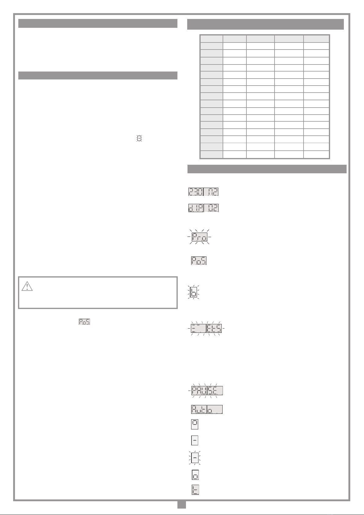
Programmatore per cancelli a una/due ante, di tipo scorrevole, a
battente o basculante con motorizzazione a 230 Vac.
Controllo digitale dei tempi di lavoro salvati in maniera separata per
ciascuna anta guidata da un display a 6 cifre. Funzionamento anche
in assenza di necorsa meccanici.
Selezione della coppia motrice. Controllo dello spunto iniziale, limitazi-
one di coppia e gestione dei rallentamenti con spazio di rallentamento
impostabile.
Predisposta per l’inserimento di una scheda radio-ricevente standard
Cardin.
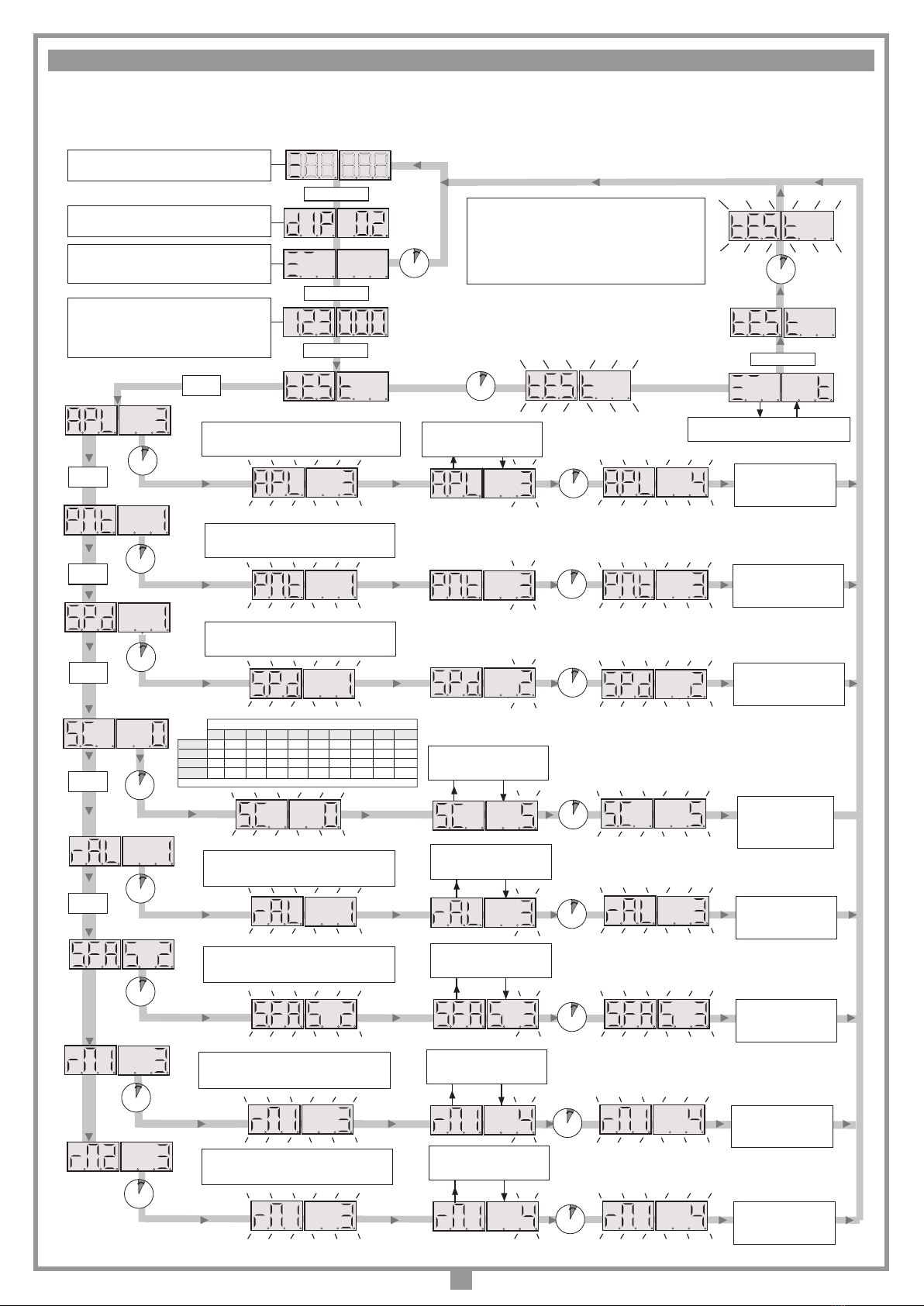
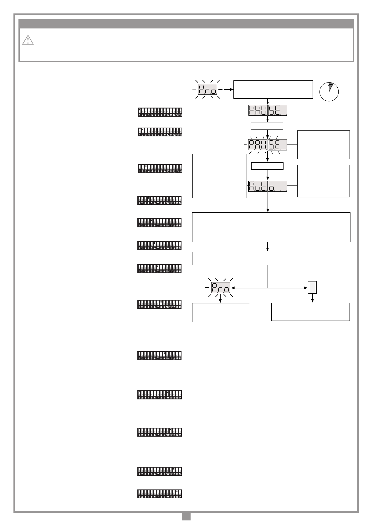
La programmazione, eseguibile mediante un solo pulsante, permette
la regolazione della corsa totale delle ante.
Attenzione! Nel programmatore è presente la tensione
a 230 Vac.
• Per la conformità alla normativa sulla sicurezza elettrica,
è proibito collegare i morsetti 3, 4 e 5direttamente ad un
circuito dove sia applicata una tensione superiore a
30 Vac/dc.
• Dopo aver installato il dispositivo, e prima di dare
tensionealla centralina, vericare che il movimento delle
ante eseguito in modo manuale (con motori sbloccati)
non abbia punti di resistenza particolarmente marcata.
• Laconnessioneall’uscita per i "carichi controllati morsetti
6 e7" permette di eseguire l’autotest (abilitabile mediante
i DIP 9 e 10) per la verica del corretto funzionamento dei
dispositivi di sicurezza.
• Accertarsi, prima di eseguire il collegamento elettrico,
che la tensione e la frequenza riportate sulla targhetta
caratteristiche corrispondano a quelle dell'impianto di
alimentazione.
• Tra la centralina di comando e la rete deve essere
interposto un interruttore onnipolare, con distanza di
apertura tra i contatti di almeno 3 mm.
• Non utilizzare cavo con conduttori in alluminio; non
stagnare l’estremità dei cavi da inserire in morsettiera;
utilizzare cavo con marcatura T min 85°C resistente agli
agenti atmosferici.
• I conduttori dovranno essere adeguatamente ssati in
prossimità della morsettiera in modo che tale ssaggio
serri sia l’isolamento che il conduttore (è sufciente una
fascetta).
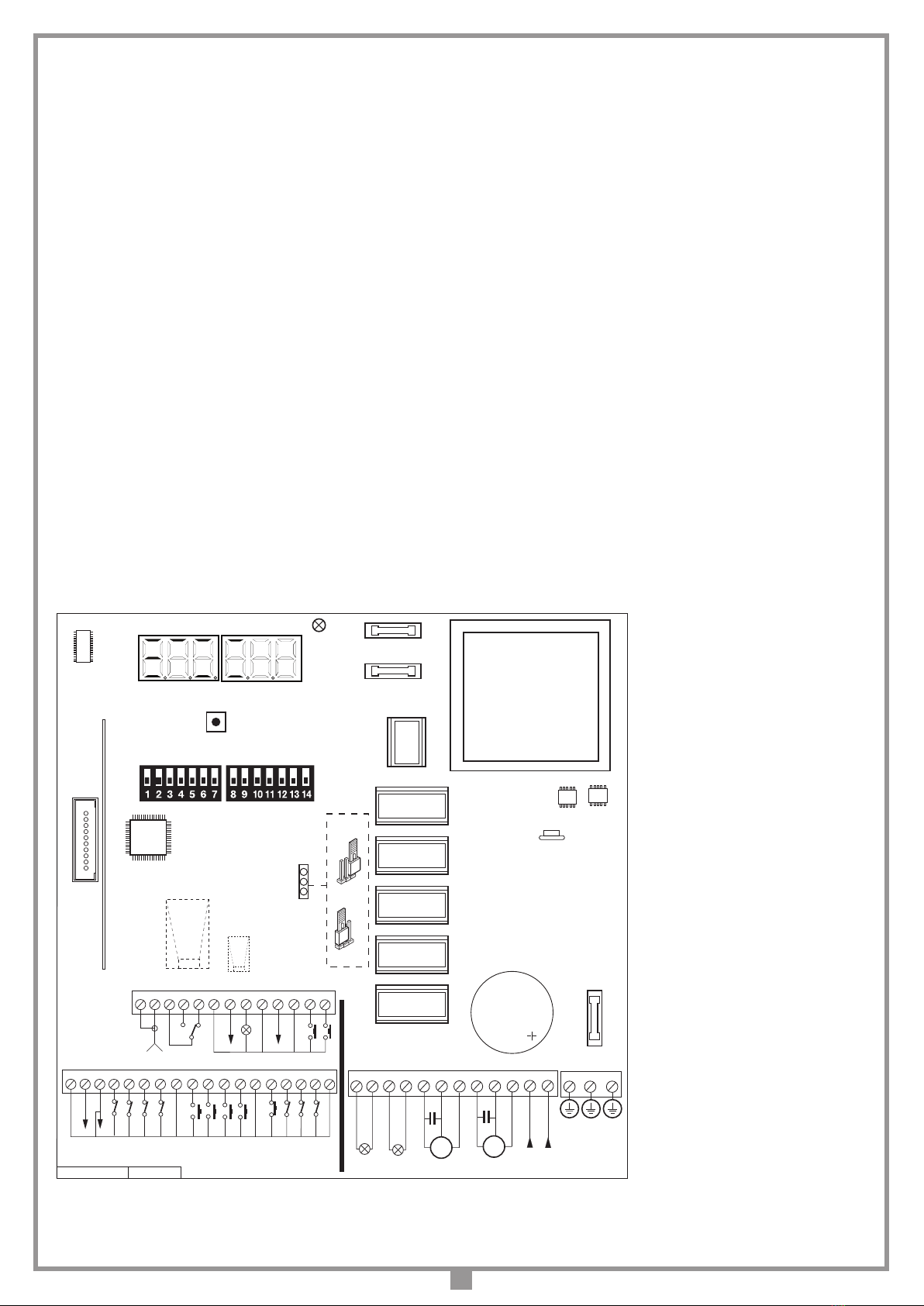
COLLEGAMENTI ALIMENTAZIONE CENTRALINA 230 Vac
• Collegare i li di comando e quelli provenienti dalle sicurezze.
• Portare l'alimentazione generale 230 Vac al programmatore
collegandolo ai morsetti 42, 43 e 44.
L= fase
N= neutro
= terra
• Collegare il motore M1 (quello che aprirà per primo) ai morsetti:
- 39 = Apertura;
- 40 = Chiusura;
- 41 = Comune.
• Collegare il motore M2 ai morsetti:
- 36 = Apertura;
- 37 = Chiusura;
- 38 = Comune.
AVVERTENZE IMPORTANTI AVVERTENZE IMPORTANTI AVVERTENZE IMPORTANTI
LEGGERE ATTENTAMENTE LE SEGUENTI AVVERTENZE PRIMA DI PROCEDERE ALL’INSTALLAZIONE.
PRESTARE PARTICOLARE ATTENZIONE A TUTTE LE SEGNALAZIONI DISPOSTE NEL TESTO. IL MANCATO
RISPETTO DI QUESTE POTREBBE COMPROMETTERE IL BUON FUNZIONAMENTO DEL SISTEMA E CREARE
SITUAZIONI DI PERICOLO GRAVE PER L'OPERATORE E GLI UTILIZZATORI DEL SISTEMA STESSO.
AVVERTENZE PER L'UTENTE
AVVERTENZE IMPORTANTI
PROGRAMMATORE ELETTRONICO
M2
OPEN
C.
CLOSE
CMN
32 33 35 36 37 38 39 40 41 42 43
34 44 45 46
LC 230V~
L
N
230V~
M1
OPEN
C.
CLOSE
CMN
LP 230V~

4
Collegamenti morsettiera
1 Massa antenna ricevitore radio
2 Centrale antenna ricevitore radio (nel caso si utilizzi un’antenna esterna colle-
garla con cavo coassiale RG58 imp. 50Ω)
3 CMN comune per CH2
4-5 CH2 uscita (contatto puro, N.A.) alimentata a parte, Vmax = 30 Vac/dc: Imax
= 1A
6 CMN comune per tutti gli ingressi/uscite
7 Uscita carichi esterni controllati 24 Vac(1)
8 LS uscita lampada spia 24 Vac 3W
9 CMN comune per tutti gli ingressi/uscite
10 ELS uscita per elettroserratura 12 Vac – 15 W
11 CMN comune per tutti gli ingressi/uscite
12 EMRG1 (N.A.) ingresso pulsante per manovra di emergenza 1
13 EMRG2 (N.A.) ingresso pulsante per manovra di emergenza 2
14 CMN comune per tutti gli ingressi/uscite
15 Uscita carichi esterni 24 Vac(1)
16 CMN comune per tutti gli ingressi/uscite
17 FCC1 (N.C.) ingresso necorsa chiusura anta 1
18 FCA1 (N.C.) ingresso necorsa apertura anta 1
19 FCC2 (N.C.) ingresso necorsa chiusura anta 2
20 FCA2 (N.C.) ingresso necorsa apertura anta 2
21 CMN comune per tutti gli ingressi/uscite
22 TAL (N.A.) ingresso pulsante di apertura limitata
23 TA (N.A.) ingresso pulsante di apertura
24 TC (N.A.) ingresso pulsante di chiusura
25 TD (N.A.) ingresso pulsante comando sequenziale
26 CMN comune per tutti gli ingressi/uscite
27 TB (N.C./8.2 kΩ) ingresso pulsante di blocco (all’apertura del contatto si
interrompe il ciclo di lavoro no ad un nuovo comando di moto) (2)
28 CSP (N.C./8.2 kΩ) ingresso per costa sensibile. L'apertura del contatto inverte
il moto sia nella fase di chiusura che nella fase di apertura (2)
29 FTCS (N.C./8.2 kΩ) ingresso per dispositivi di sicurezza (fotocellula di stop).
L'apertura del contatto blocca il moto; al ritorno nella condizione di riposo,
dopo il tempo di pausa il moto riprenderà in chiusura (solo con richiusura
automatica abilitata) (2)
30 FTCI (N.C./8.2 kΩ) ingresso per dispositivi di sicurezza (fotocellula di
inversione in chiusura). L’apertura del contatto, conseguente all’intervento
dei dispositivi di sicurezza, durante la fase di chiusura, attuerà l’inversione
del moto (2)
31 CMN comune per tutti gli ingressi/uscite
32-33 Uscita 230Vac 40W luce di cortesia
34-35 Uscita 230Vac 40W lampeggiante (attivazione continua o intermittente)
36-37-38 Uscita comando motore M2 Apertura-Chiusura-Comune
39-40-41 Uscita comando motore M1 Apertura-Chiusura-Comune
42-43 Alimentazione programmatore 230Vac 50/60Hz
44 Terra per alimentazione programmatore 230Vac 50/60Hz
45 Collegamento terra
46 Collegamento terra
Nota (1) La somma delle due uscite per carichi esterni non deve superare 10W.
Nota (2) La selezione del tipo di contatto N.C./8.2 kΩ viene effettuata da menu visua-
lizzabile sul display a 6 cifre (parametro "SC")
TUTTI I CONTATTI N.C. NON UTILIZZATI VANNO PONTICELLATI e di conse-
guenza i test sulle sicurezze corrispondenti (FTCI, FTCS – DIP9 e DIP10) devono
essere disabilitati.
Se si vuole attivare il test sulle FTCI, FTCS sia la parte trasmittente che la parte rice-
vente di tale sicurezze vanno collegate ai carichi controllati (CTRL24Vdc). Si tenga
presente che nel caso sia abilitato il test, tra la ricezione del comando e il moto delle
ante/a passa circa 1 secondo.
Alimentare il circuito e vericare che lo stato dei LED di segnalazione sia come segue:
- L1 Alimentazione scheda acceso
- L2 Segnalazione tasto blocco "TB" acceso (3)
- L3 Segnalazione fotocellule d'inversione "FTCI"acceso (3)
- L4 Segnalazione fotocellule di stop "FTCS"acceso (3)
- L5 Segnalazione costa sensibile "CSP"acceso (3)
- L6 Segnalazione tasto di apertura (TA) spento
- L7 Segnalazione tasto di chiusura (TC) spento
- L8 Segnalazione tasto di apertura limitata (TAL) spento
- L9 Segnalazione comando sequenziale (TD/CH1) spento
L7
L6
L4
L3
L8L5L2
P1
L9 D1
L1
M2
OPEN
C.
CLOSE
CMN
F1
CS1484A DC0562
32 33 35 36 37 38 39 40 41 42 43
34 44 45 46
F2
R1
PROG
LC 230V~
L
N
230V~
16 17 19 20 21 22 23 24 251814 15
TAL
TA
TB
FTCI
TD
NC NC NC NC
26 27
TC
NC
M1
OPEN
C.
CLOSE
CMN
LP 230V~
F3
ON
DS1
J1
3 4 6 7 8 9 10 11 1251 2
CMN
EMRG 2
OUT CH2
13
NO
EMRG 1
NO
CMN
ELS
12Vac
CMN
LS
CTRL
24Vac
28 29 30 31
CMN
FTCS
CSP
CMN
NCNCNCNO NONONO
CMN
FCA2
FCC2
FCA1
FCC1
24Vac
CMN
CMN
NO NO
NO
AUX
Programmatore a microcontrollore per 1-2 motori
PRG230M2
18-03-2016
DC0562 Description :
Product Code :
Date :
Drawing number :
P.J.Heath
CARDIN ELETTRONICA S.p.A - 31020 San Vendemiano (TV) Italy - via Raffaello, 36 Tel: 0438/401818 Fax: 0438/401831
Draft :
All rights reserved. Unauthorised copying or use of the information contained in this document is punishable by law
PRG230M2
POS. 1
POS. 2
D1 Display a LED a 6 cifre
DS1 Dip-switch di selezione
F1 Fusibile 1A (ritardato protezione circuito 24V)
F2 Fusibile 4A (ritardato protezione circuito 230V)
F3 Fusibile 1,6A (ritardato protezione elettroserratura)
J1 Jumper di selezione EMRG (On/Off)
P1 Tasto di programmazione (PROG)
R1 Interfaccia scheda radio ricevente standard
1
Nota
(3) ILEDsonoaccesise larelativasicurezza
non è attivata. Vericare che l'attivazione delle
sicurezze porti allo spegnimento del LED ad
esse associato.
Nel caso in cui il LED verde di alimentazione
"L1" non si accenda verificare lo stato
dei fusibili ed il collegamento del cavo di
alimentazione.
Nel caso in cui uno o più LED di sicurezza
non si accendano vericare che i contatti
dellesicurezzenon utilizzate siano ponticellate
sulla morsettiera.

5
ON
OFF
ON
OFF
ON
OFF
ON
OFF
ON
OFF
ON
OFF
ON
OFF
ON
OFF
PROCEDURA DI PROGRAMMAZIONE (Impostazioni del programmatore)
Impostazione dip-switch DS1
ATTENZIONE: se si cambia l'impostazione dei dip, tale impostazione deve
essere memorizzata; premere dunque il tasto "PROG", sul display appare la
dicitura "dIP" segnalando l’avvenuta memorizzazione.
Selezione motori (DIP1)
"ON" = Funzionamento singolo motore
"OFF" = Funzionamento doppio motore
Selezione sfasamento (DIP2)
"ON" = Sfasamento abilitato
"OFF" = Sfasamento disabilitato
Se si abilita lo sfasamento, nella manovra di apertura prima parte l’anta 1 e poi
l’anta 2, mentre in chiusura prima parte anta 2 e poi anta 1. Con lo sfasamento
disabilitato le ante si mettano in moto contemporaneamente.
Comando sequenziale TD/CH1 (DIP3)
"ON" = Comando sequenziale "apre-chiude"
L’inversione del moto si ha solamente in fase di chiusura.
"OFF" = Comando sequenziale "apre-blocco-chiude-blocco"
Richiusura automatica (DIP 4)
"ON" = Richiusura automatica abilitata
"OFF" = Richiusura automatica disabilitata
Prelampeggio (DIP 5)
"ON" = Prelampeggio inserito
"OFF" = Prelampeggio escluso
Uscita lampeggiante (DIP 6)
"ON" = Uscita lampeggiante intermittente
"OFF" = Uscita lampeggiante ssa
Lampada spia (DIP 7)
"ON" = Lampada spia intermittente *
"OFF" = Lampada spia non intermittente
*Lalampada spia lampeggia lentamentedurantel’apertura,velocementedurante
la chiusura; resta accesa quando il cancello è bloccato non completamente
chiuso, ed è spenta quando il cancello è completamente chiuso.
Modalità FTCI (DIP 8)
"ON" = FTCI attive anche in blocco
Se le fotocellule risultano in allarme, ed il cancello è in stato di blocco, non viene
accettato nessun comando di moto (nemmeno di apertura).
"OFF" = FTCI attive solo in chiusura
In entrambi i casi l'attivazione della sicurezza FTCI
durante la fase di chiusura comporta l'inversione del moto.
Test su FTCI (DIP 9)
"ON" = Test su FTCI abilitato
"OFF" = Test su FTCI disabilitato
Se si abilita il test sulle sicurezze bisogna alimentare sia la parte trasmittente che
la parte ricevente ai carichi controllati (CTRL 24 Vdc). Con il test abilitato passa
circa un secondo dalla ricezione di un comando alla sua effettiva esecuzione.
Test su FTCS (DIP 10)
“ON” = Test su FTCS abilitato
“OFF” = Test su FTCS disabilitato
Se si abilita il test sulle sicurezze bisogna alimentare sia la parte trasmittente che
la parte ricevente ai carichi controllati (CTRL 24 Vdc). Con il test abilitato passa
circa un secondo dalla ricezione di un comando alla sua effettiva esecuzione.
Elettroserratura (DIP 11)
“ON” = Elettroserratura abilitata
“OFF” = Elettroserratura disabilitata
Abilitando l’elettroserratura, prima di iniziare il moto di anta 1 si attiva l’uscita
ELS (morsetto 6) e rimane attivata per alcuni secondi.
Fine corsa motore 1 (DIP 12)
“ON” = Fine corsa motore 1 abilitati
“OFF” = Fine corsa motore 1 disabilitati
Fine corsa motore 2 (DIP 13)
“ON” = Fine corsa motore 2 abilitati
“OFF” = Fine corsa motore 2 disabilitati
Dip 14 = Non utilizzato
ON
OFF
PARTE IL CONTEGGIO DEL
TEMPO DI PAUSA (MINIMO
2 SECONDI; MASSIMO 120
SECONDI), SEGNALATO DAL
LAMPEGGIO DEL SIMBOLO
"PAUSE" SUL DISPLAY.
PREMERE PROG
ATTENZIONE! SE UNA DELLE
ANTE DOVESSE MUOVERSI IN
CHIUSURA VUOL DIRE CHE LA
CONNESSIONE MOTORE NON
È CORRETTA, PERCIÒ
RIPREMERE PROG
ANNULLANDO LA PROCEDURA
DI PROGRAMMAZIONE,
INVERTIRE LA CONNESSIONE
MOTORE (CAVO ROSSO-NERO)
E RIPETERE LA
PROGRAMMAZIONE.
DOPO AVER EFFETTUATO QUESTE MANOVRE LA LOGICA DI CONTROLLO ESEGUE UNA
MANOVRA COMPLETA DI APERTURA E CHIUSURA.
A CHIUSURA COMPLETATA IL
PROGRAMMATORE SALVA I PARAMETRI
ED ESCE DALLA PROGRAMMAZIONE.
L'OPERAZIONE NON È ANDATA
A BUON FINE. SARÀ
NECESSARIO RIPETERE LA
PROGRAMMAZIONE.
PREMERE IL TASTO PROG PER PIÙ
DI 4 SECONDI: COMPARE IL SIMBOLO
"PAUSE" CHE INDICA LA
PROGRAMMAZIONE DEL TEMPO DI PAUSA
1...4... sec.
PREMERE PROG
TERMINA IL CONTEGGIO DEL
TEMPO DI PAUSA E LE ANTE
ESEGUONO L’APERTURA
LENTAMENTE, IN MODO DA
TROVARE LO STATO DI
COMPLETAMENTE APERTO
• ANTA 1 PARTE IN APERTURA. QUANDO ARRIVA IN BATTUTA PREMERE PROG.
• ANTA 2 PARTE IN APERTURA. QUANDO ARRIVA IN BATTUTA PREMERE PROG.
• ANTA 2 PARTE IN CHIUSURA. QUANDO ARRIVA IN BATTUTA PREMERE PROG.
• ANTA 1 PARTE IN CHIUSURA. QUANDO ARRIVA IN BATTUTA PREMERE PROG.
NOTA: NEL CASO LA CENTRALE SIA CONFIGURATA PER FUNZIONAMENTO A SINGOLO MOTORE
LA PROGRAMMAZIONE SALTA I PASSAGGI DI ANTA 2.
• Èobbligatoria la presenza delle battute di apertura e chiusura per entrambe le ante.
• Accertarsi che le sicurezze siano a riposo e che la scheda sia alimentata: in caso contrario non si entra in programmazione.
ON
OFF
ON
OFF
ON
OFF
ON
OFF

6
Sul display si accendono i segmenti relativi allo
stato dei comandi (acceso = comando attivo) e
delle sicurezze (acceso = sicurezza a riposo).
Il numero di manovre rimane sempre visualizza-
to, nché non si sceglie di cambiare l'imposta-
zione. Al superamento del numero 999999 la
cifra dei milioni è fornita dal numero di punti
decimali accesi.
10 sec
PREMERE PROG
Lo stato delle sicurezze TB, FTCI, FTCS, CSP è
sempre rappresentato sul display.
Memorizzazione congurazione a DIP-SWITCH
e visualizzazione versione rmware (“02.”)
PREMERE
PROG
PREMERE
PROG
PREMERE PROG
PREMERE PROG
10 sec
Dopo 10 secondi dall’ultima
modica il sistema esce
automaticamente salvando
il valore selezionato (es. 3)
10 sec
Dopo 10 secondi dalla
ultima modica si uscirà
automaticamente salvando
il valore selezionato (es. 4)
10 sec
10 sec
PREMERE PROG
Ad ogni pressione del tasto viene
incrementato il numero (da 1 a 4).
APL = Impostazione spazio di apertura limitata (anta 1):
1 = 1/3 della corsa : 2 = metà della corsa
3 = 2/3 della corsa : 4 = corsa totale
Impostazione tempo di rallentamento
0 (rallentamento escluso) 1 (min.) - 3 - 4 - 5 (max.)
PREMERE PROG
Ad ogni pressione del tasto viene
incrementato il numero (da 0 a 5).
Nella modalità "test" (attivabile solo con motore fermo) è
possibile eseguire veriche sullo stato dei comandi e
sicurezze, ed effettuare eventuali manutenzioni.
Il lampeggiante si attiva una volta ad ogni comando
("TA-TC-TD-TAL-TB-FTCI-FTCS-CSP") ricevuto.
Per tornare al normale funzionamento premere "PROG",
facendo apparire la scritta "test", e attendere 10 secondi.
10 sec
Attivando gli ingressi ("TA-TC-TD-TAL-TB-
FTCI-FTCS-CSP") si aziona il lampeggiante.
10 sec
PREMERE PROG
PREMERE
PROG
PREMERE
PROG
Selezione del contatto di sicurezza
0 1 2 3 4 5 6 7 8 9
TB N.C. N.C. N.C. N.C. N.C. N.C. N.C. N.C. 8.2 KΩ 8.2 KΩ
FTCS N.C. N.C. N.C. N.C. 8.2 KΩ 8.2 KΩ 8.2 KΩ 8.2 KΩ N.C. N.C.
FTCI N.C. N.C. 8.2 KΩ 8.2 KΩ N.C. N.C. 8.2 KΩ 8.2 KΩ N.C. N.C.
CSP N.C. 8.2 KΩ N.C. 8.2 KΩ N.C. 8.2 KΩ N.C. 8.2 KΩ N.C. 8.2 KΩ
Per i valore da A ad F vedere il paragrafo “selezione del contatto” a pagina 7
10 sec
10 sec
PREMERE PROG
Ad ogni pressione del tasto si modica
l’impostazione (tra 0 ... 9 - A ...F).
Dopo 10 secondi dalla
ultima modica si uscirà
automaticamente salvando
il valore selezionato (es. 5)
10 sec
Dopo 10 secondi dall’ultima
modica il sistema esce
automaticamente salvando
il valore selezionato (es. 3)
10 sec
Impostazione dello sfasamento tra le ante
1 = sfasamento minimo 3 = sfasamento massimo
2 = sfasamento medio
PREMERE PROG
Ad ogni pressione del tasto viene
incrementato il numero (da 1 a 3).
PMT = Impostazione della potenza del motore.
da livello 1 (minimo) a livello 8 (massimo)
PREMERE
PROG
10 sec
10 sec
Dopo 10 secondi dall’ultima
modica il sistema esce
automaticamente salvando
il valore selezionato (es. 3)
SPd= Livello di velocità in fase di rallentamento.
1 = velocità minima 2 = velocità massima
PREMERE
PROG
10 sec
10 sec
Dopo 10 secondi dall’ultima
modica il sistema esce
automaticamente salvando
il valore selezionato (es. 2)
10 sec
Dopo 10 secondi dall’ultima
modica il sistema esce
automaticamente salvando
il valore selezionato (es. 4)
10 sec
Impostazione tempo di recupero motore 1
1 = recupero minimo 8 = recupero massimo
PREMERE PROG
Ad ogni pressione del tasto viene
incrementato il numero (da 1 a 8).
10 sec
10 sec
Impostazione tempo di recupero motore 2
1 = recupero minimo 8 = recupero massimo
PREMERE PROG
Ad ogni pressione del tasto viene
incrementato il numero (da 1 a 8).
Dopo 10 secondi dall’ultima
modica il sistema esce
automaticamente salvando
il valore selezionato (es. 4)
MENU DI VISUALIZZAZIONE
Agendo sul tasto PROG si accede in sequenza alle seguenti funzioni:
- memorizzazione dello stato dei dip-switch;
- visualizzazione dello stato dei comandi e delle sicurezze;
- visualizzazione del numero di manovre;
- ingresso in modalità "test";
- impostazione dello spazio di apertura limitata;
- regolazione potenza motore;
- selezione contatto di sicurezza
(N.C./8.2 kΩ);
- impostazione tempo di rallentamento;
- impostazione tempo di sfasamento.

SC TB FTCS FTCI CSP
0 N.C. N.C. N.C. N.C.
1 N.C. N.C. N.C. 8.2 kΩ
2 N.C. N.C. 8.2 kΩN.C.
3 N.C. N.C. 8.2 kΩ8.2 kΩ
4 N.C. 8.2 kΩN.C. N.C.
5 N.C. 8.2 kΩN.C. 8.2 kΩ
6 N.C. 8.2 kΩ8.2 kΩN.C.
7 N.C. 8.2 kΩ8.2 kΩ8.2 kΩ
8 8.2 kΩN.C. N.C. N.C.
9 8.2 kΩN.C. N.C. 8.2 kΩ
A 8.2 kΩN.C. 8.2 kΩN.C.
B 8.2 kΩN.C. 8.2 kΩ8.2 kΩ
C 8.2 kΩ8.2 kΩN.C. N.C.
D 8.2 kΩ8.2 kΩN.C. 8.2 kΩ
E 8.2 kΩ8.2 kΩ8.2 kΩN.C.
F 8.2 kΩ8.2 kΩ8.2 kΩ8.2 kΩ
7
Il controllo del comando dinamico e del contatto ausiliario (C-NA) può essere gestito
tramite radiocomando inserendo una scheda ricevente standard Cardin bicanale nel
connettore "R1" (g. 1). Il numero di canali gestibile è due, uno associato alla funzione
di comando dinamico e l'altro all'attivazione di un contatto puro ausiliario C-NA-NO
collegato ai morsetti 3,4 e 5.
Perulterioriinformazioni consultareillibrettod'istruzionifornitocon ilricevitoreascheda.
1) Automatica
Si seleziona abilitando la richiusura automatica (dip "4" in posizione "ON"). Par-
tendo dalla condizione di completamente chiuso, il comando di apertura inizia
un ciclo completo di funzionamento, che terminerà con la richiusura automatica.
La richiusura automatica entra in funzione con un ritardo pari al tempo di pausa
programmato, a partire dal termine della manovra di apertura oppure dall'istante
in cui sono intervenute le fotocellule per l'ultima volta durante il tempo di pausa
(l'intervento delle fotocellule causa un reset del tempo di pausa).
Durante il tempo di pausa, sul display lampeggia il simbolo . La pressione del
tasto di blocco durante il tempo di pausa impedisce la richiusura automatica con
conseguente blocco del lampeggio sul display. La lampada spia rimane accesa
quando il portone non è completamente chiuso.
Nota: la luce di cortesia si accende ad ogni comando di movimento impartito
al sistema, sia via lo che via radio, e si spegne dopo 30 secondi dal termine
della manovra.
2) Semi-automatica
Si seleziona disabilitando la richiusura automatica (dip "4" in posizione "OFF").
Il ciclo di lavoro è gestito con comandi separati di apertura e chiusura. Arrivato
in posizione di completa apertura il sistema attende un comando di chiusura
via radio o tramite tasto per completare il ciclo. La lampada spia rimane accesa
quando il cancello non è completamente chiuso.
3) Manovra manuale con motori sbloccati
Sbloccando i motori le ante possono essere spostate a mano.
4) Manovra di emergenza
Nelcaso incuiilprogrammatoreelettroniconon dovessepiùrispondereaicomandi
per un malfunzionamento, agire sugli ingressi EMRG1 o EMRG2 per muovere
anta 1 in modalità uomo presente. Gli ingressi EMRG1 ed EMRG2 agiscono
direttamente sul controllo del motore, escludendo la logica.
Attenzione! Durante la manovra di emergenza tutte le sicurezze
risultano disabilitate e non c'è controllo sulla posizione dell'anta:
rilasciare dunque i comandi prima dell'arrivo in battuta. Usare la
manovra di emergenza soltanto in condizioni di estrema necessità.
Dopo aver effettuato una manovra di emergenza il programmatore elettronico
"perde"laposizionedelle ante ( suldisplay)e quindi allasuccessivericezione
di un comando verrà effettuato una manovre di apertura completa.
APERTURA LIMITATA
Viene eseguita sempre su anta 1; lo spazio di apertura limitata può essere
impostato (vedi menu di visualizzazione) a 1/3, metà, 2/3 o corsa totale di anta 1.
Èpossibileeseguireil comando solo con leantecompletamentechiuse;sedip
"3"
è impostato in “OFF” e durante l’apertura limitata si attiva nuovamente il comando
“TAL”, anta 1 si bloccherà, e ad un successivo comando andrà in chiusura. A
questo punto il comando non sarà più eseguito no alla completa chiusura.
COMANDO VIA RADIO
MODALITÀ DI FUNZIONAMENTO
INDICAZIONI DEL DISPLAY (D1 - pagina 6)
Visualizzazioni all’accensione
Visualizzato per due secondi:
"
230_M2
" = modello della centralina
segnala la memorizzazione della congurazione
dei dip-switch e la versione del rmware.
Segnalazioni di allarme
Sistema non programmato
Ènecessarioentrareinmodalitàdiprogrammazioneper programmareilsistema.
Fuori posizione
Nel caso di installazione, è necessario entrare in programmazione per pro-
grammare la corsa dell'anta.
Blocco durante la programmazione tempi
Si verica quando viene attivato un contatto N.C. (FTCI, FTCS, CSP) durante
la programmazione tempi. Una volta ristabilito lo stato passivo delle sicurezze
l'anta riprende il moto automaticamente.
Errore nel test delle sicurezze
Occorre controllare lo stato delle sicurezze, vericando che vadano in allarme
(LED relativo spento) quando un ostacolo si trova in mezzo al loro raggio di
azione. Se si riscontra un’anomalia sostituire la sicurezza guasta oppure
ponticellare l’ingresso relativo e disabilitare il test relativo alla sicurezza stessa
(dip 9 o 10).
Segnalazioni di funzionamento
Programmazione del tempo di pausa
Programmazione automatica in corso
Fase di apertura
Blocco
Pausa per la richiusura automatica
(solo se abilitata)
Fase di chiusura
Modalità di test
SELEZIONE DEL CONTATTO DI SICUREZZA

8
Attention! The product has 230 Vac contacts on the
electronic card.
In conformity with the electrical safety standards it is
forbidden to connect binding posts 3, 4 and 5 directly to a
circuit that receives power greater than 30 Vac/dc.
• After having installed the device, and before powering
up the programmer, release the gates (manual release
mechanism) and move them manually, checking that they
moves smoothly and have no unusual points of resistance.
•Connectingdevicestothecontrolledoutputcontactbetween
bindingposts6and7alsoallows you to carry out the autotest
function (enabled using DIPs 9 and 10) and check that the
safety devices are functioning correctly.
• Before connecting the appliance make sure that the voltage
and frequency rated on the data plate conform to those of
the mains supply.
• An all pole trip switch with at least 3 mm between the
contacts must be installed between the unit and the mains
supply.
• Don't use cables with aluminium conductors; don't solder
the ends of cables which are to be inserted into the binding
posts; use cables marked T min 85°C and resistant to
atmospheric agents.
• The terminal wires must be positioned in such a way that
both the wire and the insulating sheath are tightly fastened
(a plastic jubilee clip is sufcient).
POWER SUPPLY CONNECTION 230 Vac
• Connect the control and security device wires.
• Run the 230 Vac mains power supply to the programmer and
connect it to binding posts 42, 43 and 44.
L = live
N = neutral
= earth
• Connect motor M1 (the one that will open rst) to binding posts:
- 41 = Opening;
- 42 = Closing;
- 43 = Common.
• Connect motor M2 to binding posts:
- 36 = Opening;
- 37 = Closing;
- 38 = Common.
• These instructions are aimed at professionally qualied "installers
of electrical equipment" and must respect the local standards
and regulations in force.
All materials used must be approved and must suit the environ-
ment in which the installation is situated.
• This product and all its relative components has been designed
and manufactured by Cardin Elettronica who have veried that
the product conforms in every aspect to the safety standards in
force.
• Any non authorised modications are to be considered improper
dangerous and the complete responsibility of the installer.
• This appliance must be used exclusively for the purpose for which
it has been made "i.e. for the command and control of 230V
Cardin motors".
• The manufacturer accepts no liability for situations arising from
the use of an electrical installation which does not conform to the
local standards and regulations in force.
Attention! Only for EU customers - WEEE marking.
This symbol indicates that once the products life-span
has expired it must be disposed of separately from
other rubbish. The user is therefore obliged to either
take the product to a suitable differential collection site
for electronic and electrical goods or to send it back to
the manufacturer if the intention is to replace it with a
new equivalent version of the same product.
Suitable differential collection, environmental friendly treatment
and disposal contributes to avoiding negative effects on the
ambient and consequently health as well as favouring the recy-
cling of materials. Illicitly disposing of this product by the owner
is punishable by law and will be dealt with according to the laws
and standards of the individual member nation.
Caution! mechanical stop anti-derailment buffers must
be installed.
To assembly the box read the instruction manual ZVL365.01 supplied
with the electronic programmer.
Electronic programmer for single/double leaf gates, sliding, hinged or
garage doors running off 230 Vac.
Digital work time control separately memorised for each gate leaf
guided by a 6-digit display. Possible operation without mechanical
travel limits.
Torque setting. Maximum power initial thrust control, torque limita-
tion and deceleration management with deceleration zone control.
The appliance is tted with an interface for the insertion of a standard
Cardin radio receiver card.
Suitable for the control of automatic gates and doors with two 230V
motors.The motor rotation speed is electronically controlled, starting
slowly and increasing in speed; the speed is reduced as it nears the
travel limit so as to enable a controlled smooth stop.
Programming is carried out using one button and allows you to set
the entire travel distance of the gates.
IMPORTANT REMARKS IMPORTANT REMARKS IMPORTANT REMARKS
READTHEFOLLOWINGREMARKSCAREFULLYBEFOREPROCEEDINGWITHTHEINSTALLATION.
PAY PARTICULAR ATTENTION TO ALL THE PARAGRAPHS MARKED WITH THE SYMBOL NOT
READING THESE IMPORTANT INSTRUCTIONS COULD COMPROMISE THE CORRECT WORKING
ORDER OF THE SYSTEM AND CREATE DANGER SITUATIONS FOR THE USERS OF THE SYSTEM.
USER INSTRUCTIONS
IMPORTANT REMARKS
ELECTRONIC PROGRAMMER
M2
OPEN
C.
CLOSE
CMN
32 33 35 36 37 38 39 40 41 42 43
34 44 45 46
LC 230V~
L
N
230V~
M1
OPEN
C.
CLOSE
CMN
LP 230V~

9
Terminal board connections
1 Outer conductor for radio receiver antenna.
2 Inner conductor for radio receiver antenna (if an external antenna is tted use
a coaxial type cable RG58 with an impedance of 50Ω)
3 CMN per CH2
4-5 CH2 Potential free N.O. contact requires separate power supply Vmax = 30
Vac/dc: Imax = 1A
6 CMN common for all inputs and outputs
7 24 Vdc controlled output, powering external loads (1)
8 LS output for an indicator light 24 Vac 3W
9 CMN common for all inputs and outputs
10 ELS electric lock output 12 Vac – 15 W
11 CMN common for all inputs and outputs
12 EMRG1 (NO contact) emergency manoeuvring button input 1
13 EMRG2 (NO contact) emergency manoeuvring button input 2
14 CMN common for all inputs and outputs
15 24 Vdc output, powering external loads ((1)
16 CMN common for all inputs and outputs
17 FCC1 (N.C.) gate 1closing travel limit input
18 FCA1 (N.C.) gate 1opening travel limit input
19 FCC2 (N.C.) gate 2closing travel limit input
20 FCA2 (N.C.) gate 2opening travel limit input
21 CMN common for all inputs and outputs
22 TAL (NO contact) limited opening button input
23 TA (NO contact) opening button input
24 TC (NO contact) closing button input
25 TD (NO contact) dynamic button input
26 CMN common for all inputs and outputs
27 TB (N.C./8.2 kΩ) stop button input (The opening of this contact interrupts the
cycle until a new movement command is given) (2)
28 CSP (N.C./8.2 kΩ) safety edge input. Opening this contact will provoke a travel
direction inversion during the closing stage and during the opening stage (2)
29 FTCS (N.C./8.2 kΩ) The opening of this contact will block all movement, until
the obstruction has been removed and the pause time has elapsed, due to
the safety device cutting in, the door will then continue moving in the closing
direction (only with automatic reclosing enabled) (2)
30 FTCI (N.C./8.2 kΩ) safety and control devices in input (photocells invert
the travel direction when an obstruction is detected). Opening this contact
will provoke a travel direction inversion during closure due to the cutting
in of the safety device (2)
31 CMN common for all inputs and outputs
32-33 230Vac 40W courtesy light output
34-35 230Vac 40W warning light output (intermittent or continuous activation)
36-37-38 Motor M2 in output Opening- Closing- Common
39-40-41 Motor M1 in output Opening- Closing- Common
42-43 Electronic programmer power supply 230Vac 50/60Hz
44 Electronic programmer earth wire 230Vac 50/60Hz
45 Earth connection
46 Earth connection
Note (1) The total of the 2 external device outputs must not exceed 10 W.
Note (2) The selection of the type of contact (
N.C./8.2 kΩ) is carried out using parameter
"SC" on the six-gure display.
ALL UNUSED NC CONTACTS MUST BE JUMPED and consequently
the security device test must also be deactivated (FTCI , FTCS - Dip 9 and
Dip 10 "OFF").
IfyouwanttoactivatetheFTCI, FTCS test both the transmissionand receiver
parts of the security devices must be connected to the binding post marked
"CTRL 24 Vdc". If the test is active there will be a 1 second delay between
the command transmission and movement of the gate/s.
Switch on the power and make sure that the indicator LEDs are in the fol-
lowing condition.
- L1 Power on ON
- L2 Indicator for the blocking button "TB" ON
(3)
- L3 Indicator for the inverting photoelectric cells "FTCI" ON
(3)
- L4 Indicator for the stop photoelectric cells "FTCS" ON
(3)
- L5 Indicator for the safety edge "CSP" ON
(3)
- L6 Indicator for the opening button "TA" OFF
- L7 Indicator for the opening button "TC" OFF
- L8 Indicator for the limited opening button "TAL" OFF
- L9 Indicator for the sequential command "TD/CH1" OFF
L7
L6
L4
L3
L8L5L2
P1
L9 D1
L1
M2
OPEN
C.
CLOSE
CMN
F1
CS1484A DC0562
32 33 35 36 37 38 39 40 41 42 43
34 44 45 46
F2
R1
PROG
LC 230V~
L
N
230V~
16 17 19 20 21 22 23 24 251814 15
TAL
TA
TB
FTCI
TD
NC NC NC NC
26 27
TC
NC
M1
OPEN
C.
CLOSE
CMN
LP 230V~
F3
ON
DS1
J1
3 4 6 7 8 9 10 11 1251 2
CMN
EMRG 2
OUT CH2
13
NO
EMRG 1
NO
CMN
ELS
12Vac
CMN
LS
CTRL
24Vac
28 29 30 31
CMN
FTCS
CSP
CMN
NCNCNCNO NONONO
CMN
FCA2
FCC2
FCA1
FCC1
24Vac
CMN
CMN
NO NO
NO
AUX
Programmatore a microcontrollore per 1-2 motori
PRG230M2
18-03-2016
DC0562 Description :
Product Code :
Date :
Drawing number :
P.J.Heath
CARDIN ELETTRONICA S.p.A - 31020 San Vendemiano (TV) Italy - via Raffaello, 36 Tel: 0438/401818 Fax: 0438/401831
Draft :
All rights reserved. Unauthorised copying or use of the information contained in this document is punishable by law
PRG230M2
POS. 1
POS. 2
D1
Six-segment LED display
DS1
Selection dip-switch
F1 1A fuse (delayed 24V
circuit protection
)
F2 4A fuse (delayed 230V
circuit protection
) )
F3 1,6A fuse (delayed
electric lock protection
)
J1 EMRG selection jumper (On/Off)
P1 Programming button (PROG)
R1
Standard radio receiver interface
Note(3) Checkthattheactivationof the safety
devicesswitches thecorrespondingLEDsoff.
If the green power on LED "L1" doesn't light
up check the condition of the fuses and the
power cable connection.
If one or more of the safety LEDs do not
light up check the contacts of the relative
security devices and check that the unused
safety device contacts have been bridged.

10
• The installation of both anti-derailment buffers is absolutely obligatory before starting programming.
• Make sure the safety devices are at rest and the ECU is receiving power otherwise you will not be able to enter programming.
PROGRAMMING PROCEDURE (Setting the programmer)
Dip-switch settings DS1
CAUTION: If you change the dip settings you must memorise them; press the
"PROG" button, "dIP" will appear on the display indicating that the settings have
been memorised.
Motor selection (DIP1)
"ON" = Single motor operation
"OFF" = Double motor operation
Opening direction gate delay (DIP 2)
"ON" = Gate delay enabled
"OFF" = Gate delay disabled
Ifyouenable gate delaythefollowingwilloccur:during the opening movementgate
leaf 1 moves rst and then gate leaf 2. In the closing direction gate leaf 2moves
rstthengate leaf 1. Ifgatedelayisdisabled both gate leavesmovesimultaneously.
Sequential command TD/CH1
(DIP3)
"ON" = Sequential command "open-close"
Travel direction inversion only during closing.
"OFF" = Sequential command "open-block-close-block"
Automatic reclosing (DIP4)
"ON" = Automatic reclosing enabled
"OFF" = Automatic reclosing disabled
Pre-flashing (DIP 5)
"ON" = Pre-ashing activated
"OFF" = Pre-ashing excluded
Warning light output (DIP 6)
"ON" = Warning light output intermittent
"
OFF" = Warning light output xed
Indicator light (DIP 7)
"ON" = Indicator light intermittent*
"OFF" = Indicator light xed
* The indicator light ashes slowly during opening, rapidly during closing; remains
lit when the gate is blocked but not completely closed and is off when the gate
is completely closed.
FTCI mode (DIP 8)
"ON" = FTCI also active when the gate is blocked
If the photocells are in alarm and the gate is blocked, no movement commands
will be accepted (even opening commands).
"OFF" = FTCI active only during closing
In both cases activating the FTCI safety device during the closing stage will force
travel direction inversion.
FTCI test (DIP 9)
"ON" = FTCI test enabled
"OFF" = FTCI test disabled
If you enable the security test you will have to connect both the transmitter and
the receiver to the controlled load output (CTRL 24 Vdc). When the test is enabled
one second will pass between receiving a command and carrying it out.
FTCS test (DIP 10)
"ON" = FTCS test enabled
"OFF" = FTCS test disabled
If you enable the security test you will have to connect both the transmitter and
the receiver to the controlled load output (CTRL 24 Vdc). When the test is enabled
one second will pass between receiving a command and carrying it out.
Electric lock (DIP 11)
"ON" = Electric lock enabled
"OFF" = Electric lock disabled
If the electric lock is enabled the ELS output (binding post 6) will be activated
before gate leaf 1 moves and will remain active until gate leaf one has moved
for a few seconds.
Travel limit motor 1 (DIP 12)
“ON” = Travel limit motor 1 enabled
“OFF” = Travel limit motor 1 disabled
Travel limit motor 2 (DIP 13)
“ON” = Travel limit motor 2 enabled
“OFF” = Travel limit motor 2 disabled
Dip 14 = Not used
• GATE LEAF 1 STARTS TO OPEN. WHEN IT ARRIVES AT THE TRAVEL LIMIT PRESS PROG.
• GATE LEAF 2 STARTS TO OPEN. WHEN IT ARRIVES AT THE TRAVEL LIMIT PRESS PROG.
• GATE LEAF 2 STARTS TO CLOSE. WHEN IT ARRIVES AT THE TRAVEL LIMIT PRESS PROG.
• GATE LEAF 1 STARTS TO CLOSE. WHEN IT ARRIVES AT THE TRAVEL LIMIT PRESS PROG.
NOTE: IF THE PROGRAMMER IS SET TO WORK A SINGLE MOTOR THE PROGRAMMING WILL
EXCLUDE THE STEPS FOR GATE LEAF 2.
AFTER HAVING CARRIED OUT THIS MANOEUVRE THE LOGIC CONTROL WILL OPEN THEN
CLOSE THE GATE LEAVES COMPLETELY IN ORDER TO CALIBRATE THE CURRENT SENSOR.
WHEN THE GATE REACHES THE
COMPLETELY CLOSED POSITION THE
PROGRAMMER SAVES THE PARAMETERS
AND QUITS THE PROGRAMMING MODE
THE OPERATION HAS NOT
SUCCEEDED. YOU WILL HAVE
TO REPEAT THE
PROGRAMMING PROCEDURE.
PRESS THE PROG BUTTON FOR MORE
THAN 4 SECONDS: THE "PAUSE" SYMBOL
WILL APPEAR INDICATING THAT YOU ARE
IN THE PAUSE PROGRAMMING MODE
1...4... sec.
PRESS PROG
THE PAUSE TIME COUNT
ENDS AND THE DOOR OPENS
SLOWLY IN ORDER TO FIND
THE COMPLETELY OPEN
POSITION.
THE PAUSE TIME COUNT
WILL START (MIN. 2
SECONDS: MAX 120
SECONDS) INDICATED BY
THE "PAUSE" SYMBOL
FLASHING ON THE DISPLAY
PRESS PROG
ATTENTION! IF THE GATE MOVES
IN THE CLOSING DIRECTION THE
MOTOR CONNECTION IS
INCORRECT. PRESS “PROG”
AGAIN TO CANCEL THE
PROGRAMMING PROCEDURE,
INVERT THE MOTOR
CONNECTION (RED AND BLACK
CABLE) AND REPEAT THE
PROGRAMMING PROCEDURE.
ON
OFF
ON
OFF
ON
OFF
ON
OFF
ON
OFF
ON
OFF
ON
OFF
ON
OFF
ON
OFF
ON
OFF
ON
OFF
ON
OFF
ON
OFF

11
DISPLAY MENU
The segments regarding the command status
(LED “ON” = command active) and safety status
(LED “ON” = safety device at rest) light up.
The number of manoeuvres appears on the display.
This number always remains visible until you
change the setting. Once 999999 has been
exceeded the lighting up of the decimal point on
the display equals 1 million + the six gure number.
10 sec
PRESS PROG
The status of the security devices TB, FTCI, FTCS
and CSP are always shown on the display
.
Memorising the DIP-SWITCH settings and displaying
the rmware version (“02.”)
PRESS
PROG
PRESS
PROG
PRESS PROG
PRESS PROG
10 s after the last
modication you will
automatically exit the mode
and the selected values will
be saved (eg. 4)
10 sec
10 sec
PRESS PROG
Each time the button is pressed the
number increases (from 1 to 4).
APL = Setting the limited opening space (gate1):
1 = 1/3 of the distance : 2 = half the distance
3 = 2/3 of the distance : 4 = the entire distance
In the "test" mode (activated when the motor has
stopped) it is possible to check the status of the
command and safety devices.
The warning lights will activate once, each time a
“TA-TC-TAL-TD-TB-FTCI-FTCS-CSP” command is
received. To return to the normal mode press the button
again “test” will appear, then wait for 10 seconds.
10 sec
10 sec
PRESS PROG
When the ("TA-TC-TD-TAL-TB- FTCI-FTCS-CSP")
inputs are activated the warning lights will light up.
10 sec
10 s after the last
modication you will
automatically exit the mode
and the selected values will
be saved
(eg. 3)
10 sec
Deceleration time settings
0 (deceration excluded) 1 (min.) 2 - 3 - 4 - 5 max.)
PRESS PROG
Each time the button is pressed
the number increases (from 1 to 3)
.
10 sec
10 s after the last
modication you will
automatically exit the mode
and the selected values will
be saved
(eg. 3)
10 sec
Setting the delay between the gates
1 = minimum gate delay 3 = maximum gate delay
2 = medium gate delay
PRESS PROG
Each time the button is pressed the
number increases (from 1 to 3)
.
PRESS
PROG
PRESS
PROG
Selecting the type of security contact
0 1 2 3 4 5 6 7 8 9
TB N.C. N.C. N.C. N.C. N.C. N.C. N.C. N.C. 8.2 KΩ 8.2 KΩ
FTCS N.C. N.C. N.C. N.C. 8.2 KΩ 8.2 KΩ 8.2 KΩ 8.2 KΩ N.C. N.C.
FTCI N.C. N.C. 8.2 KΩ 8.2 KΩ N.C. N.C. 8.2 KΩ 8.2 KΩ N.C. N.C.
CSP N.C. 8.2 KΩ N.C. 8.2 KΩ N.C. 8.2 KΩ N.C. 8.2 KΩ N.C. 8.2 KΩ
For the values from A to F see the paragraph “contact selection” on page 12
10 sec
10 sec
PRESS PROG
Each time the button is
pressed the setting changes
(from 0 ... 9 - A ...F).
10 s after the last
modication you will
automatically exit the mode
and the selected values will
be saved
(
eg.
5)
PMT = Motor power setting.
from level 1 (minimum to level 8 (maximum)
PRESS
PROG
10 sec
10 sec
10 s after the last modication
you will automatically exit the
mode and the selected values
will be saved (eg. 3)
SPd= Speed level during deceleration.
1 = minimum speed 2 = maximum speed
PRESS
PROG
10 sec
10 sec
10 s after the last modication
you will automatically exit the
mode and the selected values
will be saved (eg. 2)
10 sec
10 sec
Setting the recovery time for motor 1
1 = minimum recovery 8 = maximum recovery
PRESS PROG
Each time the button is pressed the
number increases (from 1 to 8)
.
10 sec
10 sec
Setting the recovery time for motor 2
1 = minimum recovery 8 = maximum recovery
10 s after the last
modication you will
automatically exit the mode
and the selected values will
be saved
(eg. 4)
10 s after the last
modication you will
automatically exit the mode
and the selected values will
be saved
(eg. 4)
PRESS PROG
Each time the button is pressed the
number increases (from 1 to 8)
.
Using the PROG button you can access the following functions in sequence:
- memorising the status of the dip-switches;
- display the status of the command and safety devices;
- display the number of manoeuvres;
- access the "test" mode;
- set the limited opening distance;
- set the motor power level;
- selecting the security contact
(N.C./8.2 kΩ);
- setting the deceleration time;
- setting the gate delay time.

SC TB FTCS FTCI CSP
0 N.C. N.C. N.C. N.C.
1 N.C. N.C. N.C. 8.2 kΩ
2 N.C. N.C. 8.2 kΩN.C.
3 N.C. N.C. 8.2 kΩ8.2 kΩ
4 N.C. 8.2 kΩN.C. N.C.
5 N.C. 8.2 kΩN.C. 8.2 kΩ
6 N.C. 8.2 kΩ8.2 kΩN.C.
7 N.C. 8.2 kΩ8.2 kΩ8.2 kΩ
8 8.2 kΩN.C. N.C. N.C.
9 8.2 kΩN.C. N.C. 8.2 kΩ
A 8.2 kΩN.C. 8.2 kΩN.C.
B 8.2 kΩN.C. 8.2 kΩ8.2 kΩ
C 8.2 kΩ8.2 kΩN.C. N.C.
D 8.2 kΩ8.2 kΩN.C. 8.2 kΩ
E 8.2 kΩ8.2 kΩ8.2 kΩN.C.
F 8.2 kΩ8.2 kΩ8.2 kΩ8.2 kΩ
12
The dynamic command and auxiliary contact (C-NO) can be controlled via
radio by inserting a 2-channel Cardin standard radio receiver card into the
interface "R1" (g. 1). It is possible to control two channels, one controlling
the dynamic command and the other controlling the C-N.O. contact between
binding posts 3, 4 and 5.
For more information please read the instructions which are supplied with
your receiver card.
1) Automatic
Selected by enabling automatic reclosing (dip "4" in position "ON"). When the
door is completely closed the opening command will start a complete cycle
which will end with automatic reclosing.
Automatic reclosing starts after the programmed pause period has elapsed
when the opening cycle has been completed or straight away after the inter-
vention of a photoelectric cell (the intervention of a photoelectric cell causes
the pause time to be reset).
During the pause time the symbol will ash on the display and pressing
the blocking button during this period will stop automatic reclosing and con-
sequently stop the display from ashing.
The indicator light remains lit until the closing manoeuvre has terminated.
Note: the courtesy light switches on each time a movement command is given
(both via cable or via radio) and switches off 30 seconds after the manoeuvre
has been completed.
2) Semiautomatic
Selected by deactivating automatic reclosing (dip "4" in position "OFF"). Work
cycle control using separate opening and closing commands. When the door
has reached the completely open position the system will wait until it receives
a closing command either via an external control button or via radio control,
before completing the cycle.
The indicator light remains lit until the closing manoeuvre has terminated.
3) Manual manoeuvring with released motors
Releasing the motor the gate can be moved by hand.
4) Emergency manoeuvre
If the electronic programmer no longer responds to commands due to a
malfunction you may use the EMRG1 or EMRG2 inputs to move the gate leaf
manually. The EMRG1 or EMRG2 inputs directly command the motor without
passing through the logic control.
Attention! During the emergency manoeuvre all safety devices
are disabled and there is no gate positioning control: release the
commands before you are at the mechanical travel buffer. Only
use the emergency manoeuvre in cases of extreme necessity.
After you have carried out an emergency manoeuvre the electronic programmer
will lose the position of the gate ( son the display) and therefore when
normal operation is restored it will carry out a complete opening manoeuvre.
LIMITED OPENING
This always effects gate 1; the limited opening space can be set (see display
menu) to 1/3, half, 2/3 or the entire opening distance for gate 1.
The command can only be carried out with both gates completely closed; if
dip "3"is set to “OFF” and during opening you activate the “TAL” command
again gate leaf 1 will block and when it receives the next command it will move
in the closing direction.
At this point the command cannot be used again until complete closure.
REMOTE CONTROL (fig. 1 - page 2)
FUNCTION MODES
SELECTING THE SECURITY CONTACT TYPE
Start up display
Shown for 2 seconds
"
230_M2
" = ECU model
Indicates the dip-switch setting memorisation
stage and rmware version.
Alarm indications
System not programmed
You have to enter the programming mode to program the system.
Out of position
When carrying out an installation you will have to enter programming in order
to program the gate travel distances.
Block during time programming
This happens when an N.C. contact is activated (FTCI, FTCS, CSP) during
time programming or repositioning. Once the passive state of the security
devices has been reset the gate/door will start moving again automatically.
Safety device test error
Check the condition of the safety devices and make sure that the alarm cuts
in when an obstacle interferes with the beam (the relative LED will switch off).
In case of anomalies replace the damaged safety device or bridge the contact
and deactivate the safety test (dip 9, 10).
Operating indications
Pause time programming
Automatic programming under way
Opening stage
Block
Pause for automatic reclosing
(if activated)
Closing stage
Test mode
INDICATIONS ON THE DISPLAY (D1, page 9)

13
• Ce livret est destiné à des personnes titulaires d'un certicat d'aptitude
professionnelle pour l'installation des "APPAREILS ÉLECTRIQUES"
et requiert une bonne connaissance de la technique appliquée
professionnellement, ainsi que des normes en vigueur.
Les matériels utilisés doivent être certiés et être adaptés aux conditions
atmosphériques du lieu d'implantation.
• Ce produit a été projeté et fabriqué entièrement par Cardin Elettronica
qui a pris soin également de vérier la conformité de ses caractéristiques
à celles requises par les normes en vigueur.
• Une diverse utilisation des produits ou leur destination à un usage
différent de celui prévu et/ou conseillé n'a pas été expérimentée par le
Constructeur. Par conséquent, les travaux effectués sont entièrement
sous la responsabilité de l'installateur.
• Le programmateur décrit dans le présent livret d’instructions doit être
destiné exclusivement à l’utilisation pour laquelle il a été expressément
conçu, c’est-à-dire pour “la commande et le contrôle de moteurs
Cardin 230V”.
• Le Fabricant décline toute responsabilité en cas d’installation électrique
non conforme aux normes en vigueur.
Attention! Seulement pour les clients de l'EU - Marquage WEEE.
Ce symbole indique l’obligation de ne pas éliminer l’appareil, à la
n de sa durée de vie, avec les déchets municipaux non triés et
de procéder à sa collecte sélective. Par conséquent, l’utilisateur
doit remettre l’appareil à un centre de collecte sélective des
déchets électroniques et électriques ou au revendeur qui est
tenu, lorsqu’il fournit un nouvel appareil, de faire en sorte que
les déchets puissent lui être remis, sur une base de un pour
un, pour autant que l’appareil soit de type équivalent à celui
qu’il fournit.
La collecte sélective des équipements électriques et électroniques en
vue de leur valorisation, leur traitement et leur élimination dans le respect
de l’environnement contribue à éviter la nocivité desdits équipements
pour l’environnement et pour la santé et à encourager leur recyclage.
L’élimination abusive de l’équipement de la part du détenteur nal
comporte l’application des sanctions administratives prévues par les
normes en vigueur dans l’État Membre d’appartenance.
ATTENTION! Il est impératif d’installer le butée mécanique du
vantail.
Pour le montage du boîtier, consulter la notice ZVL365.01 fournie avec
le programmateur électronique.
Programmateur pour portails à un ou deux vantaux, coulissants,
battants ou basculants avec motorisation à 230 Vac.
Contrôle digital des temps de travail sauvegardés séparément pour
chaque vantail avec indications sur afcheur à 6 chiffres. Possibilité
de fonctionnement même à défaut de ns de course mécaniques.
Sélection du couple moteur. Contrôle du lancement initial, limitation du
couple et gestion des décélérations avec distance de ralentissement
réglable.
L’appareil est prédisposé pour l’insertion d’une carte radio réceptrice
standard Cardin.
La programmation, réalisable avec un seul bouton, permet de régler
la course totale des vantaux.
Attention! En certains points de la carte du programmateur
il y a une tension de 230 Vac.
Conformémentauxnormesde sécurité électrique, il est interdit
de brancher les bornes 3, 4 et 5directement à un circuit où
est appliquée une tension supérieure à 30 Vac/dc.
• Après avoir monté le dispositif, et avant de mettre sous
tension la centrale, contrôler en manœuvrant manuellement
les vantaux (avec moteurs débrayés), qu’il n’y ait pas de points
de résistance particulièrement prononcés.
• La connexion à la sortie prévue pour les dispositifs externes
contrôlés(bornes6et7)permet d’effectuerl’autotest(activable
au moyen des DIPs 9 et 10) pour la vérication du bon
fonctionnement des dispositifs de sécurité.
• Avantd'effectuerlebranchementélectrique,contrôlerque la
tension et la fréquence indiquées sur la plaquette signalétique
correspondent aux données du réseau d'alimentation
électrique.
• Entrelacentraledecommande et leréseaudoitêtreinterposé
un interrupteur omnipolaire avec ouverture des contacts d'au
moins 3 mm.
• Ne pas utiliserde câble avec des conducteurs enaluminium;
ne pas étamer l'extrémité des câbles à insérer dans le bornier;
utiliser un câble marqué T min. 85°C résistant à l'action des
agents atmosphériques.
• Lesconducteurs devrontêtreadéquatementxés àproximité
du bornier. Cette xation devra bloquer tant l'isolation que le
conducteur (il suft d'un collier).
BRANCHEMENT DE L’ALIMENTATION DE LA CENTRALE 230 Vac
• Brancher les ls de commande et ceux qui proviennent des dispositifs
de sécurité.
• Tirer le câble d’alimentation générale 230 Vac jusqu’au
programmateur et le brancher au bornes 42, 43 et 44.
L= phase
N= neutre
= terre
• Brancher le moteur M1 (celui du vantail qui s’ouvre en premier)
au bornes:
- 39 = Ouverture;
- 40 = Fermeture;
- 41 = Commun;
• Brancher le moteur M2 au bornes:
- 36 = Ouverture;
- 37 = Fermeture;
- 38 = Commun;
CONSIGNES IMPORTANTES! CONSIGNES IMPORTANTES! CONSIGNES IMPORTANTES!
LIRE ATTENTIVEMENT LES CONSIGNES SUIVANTES AVANT DE PROCÉDER À LA POSE. PRÊTER
GRANDE ATTENTION À TOUTES LES SIGNALISATIONS QUI SE TROUVENT DANS LE TEXTE. LE NON
RESPECT DE CES CONSIGNES POURRAIT COMPROMETTRE LE BON FONCTIONNEMENT DU SYSTÈME.
CONSIGNES POUR L’UTILISATEUR
CONSIGNES IMPORTANTES!
PROGRAMMATEUR ÉLECTRONIQUE
M2
OPEN
C.
CLOSE
CMN
32 33 35 36 37 38 39 40 41 42 43
34 44 45 46
LC 230V~
L
N
230V~
M1
OPEN
C.
CLOSE
CMN
LP 230V~

14
Branchements du bornier
1 Masse antenne récepteur radio
2 Âme antenne récepteur radio (en cas d’utilisation d’une antenne externe, la
brancher au moyen d’un câble coaxial RG58 imp. 50Ω)
3 CMN commun pour CH2
4-5 CH2 sortie (contact non alimenté, N.O.) alimentation séparée, Vmaxi. = 30
Vac/dc, Imaxi.=1A
6 CMN commun pour toutes les entrées/sorties
7 Sortie dispositifs externes contrôlés 24 Vac (1)
8 LS sortie lampe témoin 24 Vac 3W
9 CMN commun pour toutes les entrées/sorties
10 ELS sortie pour serrure électrique 12 Vac – 15 W
11 CMN commun pour toutes les entrées/sorties
12 EMRG1 (N.O.) entrée bouton pour la manœuvre d’urgence 1
13 EMRG2 (N.O.) entrée bouton pour la manœuvre d’urgence 214
CMN commun pour toutes les entrées/sorties
14 CMN commun pour toutes les entrées/sorties
15 Sortie dispositifs externes 24 Vdc (1)
16 CMN commun pour toutes les entrées/sorties
17 FC1 (N.F.) entrée n de course en fermeture vantail 1
18 FA1 (N.F.) entrée n de course en ouverture vantail 1
19 FC2 (N.F.) entrée n de course en fermeture vantail 2
20 FA2 (N.F.) entrée n de course en ouverture vantail 2
21 CMN commun pour toutes les entrées/sorties
22 TAL (N.O.) entrée bouton d’ouverture partielle
23 TA (N.O.) entrée bouton d’ouverture
24 TC (N.O.) entrée bouton de fermeture
25 TD (N.O.) entrée bouton de commande séquentielle
26 CMN commun pour toutes les entrées/sorties
27 TB(N.F. /8.2 kΩ) entrée bouton de blocage(l’ouverture dece contact interrompt
le cycle de travail jusqu’à une nouvelle commande de manœuvre) (2)
28 CSP (N.F. /8.2 kΩ) entrée pour bord de sécurité. L'ouverture de ce contact
inverse le sens de marche aussi bien en fermeture qu'en ouverture (2)
29 FTCS (N.F. /8.2 kΩ) entrée pour dispositifs de sécurité (cellule photoélectrique
de stop). L'ouverture de ce contact stoppe la manœuvre au retour à l’état de
veille,aprèsle tempsdepause,lamanœuvrereprendraenfermeture(seulement
si la refermeture automatique a été validée) (2)
30 FTCI (N.F. /8.2 kΩ) entrée pour dispositifs de sécurité (cellule
photoélectrique d’inversion en fermeture). L’ouverture de ce
contact, suite à l’intervention des dispositifs de sécurité, durant la
phase de fermeture, provoquera une inversion de la manœuvre (2)
31 CMN commun pour toutes les entrées/sorties
27-28 Sortie 230 Vac 40W éclairage de zone
29-30 Sortie 230Vac40W clignoteur(activationcontinue ouintermittente)
31-32-33 Sortie commande moteur M2 Ouverture-Fermeture-Commun
34-35-36 Sortie commande moteur M1 Ouverture-Fermeture-Commun
37-38 Alimentation programmateur 230 Vac 50/60Hz
39 Terre pour alimentation programmateur 230 Vac 50/60Hz
40 Sortie terre
41 Sortie terre
Nota(1) La somme des deux sorties pour dispositifs externes ne doit pas être supé-
rieure à 10 W.
Nota (2) La sélection du type de contact N.F./8.2 kΩ s'effectue sur le menu visionnable
sur l'afcheur à 6 chiffres (paramètre "SC")
FAIRE UN PONT SUR TOUS LES CONTACTS N.F. INUTILISÉS et, en conséquence,
invalider les tests sur les dispositifs de sécurité correspondants (FTCI, FTCS – DIP9
et DIP10 en position "OFF").
Si l’on désire activer le test sur les dispositifs FTCI et FTCS, la partie émettrice tout
comme la partie réceptrice de ces dispositifs doivent être branchées à la borne
pour dispositifs externes contrôlés (CTRL 24Vdc). Tenir compte du fait qu’en cas de
validation du test, 1 seconde environ s’écoule entre la réception de la commande et
le lancement de la manœuvre du/des vantail/vantaux. Mettre sous tension le circuit
et vérier si l’état des LEDs de signalisation est conforme aux indications suivantes:
- L1 Mise sous tension de la carte allumée
- L2 Signalisation touche de blocage “TB” allumée(3)
- L3 Signalisation cellules photoélectrique d’inversion “FTCI” allumée(3)
- L4 Signalisation cellules photoélectrique de stop “FTCS” allumée(3)
- L5 Signalisation bord de sécurité “CSP” allumée(3)
- L6 Signalisation touche d’ouverture (TA) éteinte
- L7 Signalisation touche de fermeture (TC) éteinte
- L8 Signalisation touche d’ouverture partielle (TAL) éteinte
- L9 Signalisation commande séquentielle (TD/CH1) éteinte
L7
L6
L4
L3
L8L5L2
P1
L9 D1
L1
M2
OPEN
C.
CLOSE
CMN
F1
CS1484A DC0562
32 33 35 36 37 38 39 40 41 42 43
34 44 45 46
F2
R1
PROG
LC 230V~
L
N
230V~
16 17 19 20 21 22 23 24 251814 15
TAL
TA
TB
FTCI
TD
NC NC NC NC
26 27
TC
NC
M1
OPEN
C.
CLOSE
CMN
LP 230V~
F3
ON
DS1
J1
3 4 6 7 8 9 10 11 1251 2
CMN
EMRG 2
OUT CH2
13
NO
EMRG 1
NO
CMN
ELS
12Vac
CMN
LS
CTRL
24Vac
28 29 30 31
CMN
FTCS
CSP
CMN
NCNCNCNO NONONO
CMN
FCA2
FCC2
FCA1
FCC1
24Vac
CMN
CMN
NO NO
NO
AUX
Programmatore a microcontrollore per 1-2 motori
PRG230M2
18-03-2016
DC0562 Description :
Product Code :
Date :
Drawing number :
P.J.Heath
CARDIN ELETTRONICA S.p.A - 31020 San Vendemiano (TV) Italy - via Raffaello, 36 Tel: 0438/401818 Fax: 0438/401831
Draft :
All rights reserved. Unauthorised copying or use of the information contained in this document is punishable by law
PRG230M2
POS. 1
POS. 2
D1 Afcheur à LEDs 6 chiffres
DS1 Dip-switch de sélection
F1 Fusible 1A (retardé protection circuit 24V)
F2 Fusible 4A (retardé protection circuit 230V)
F3 Fusible 1,6A (retardé protection serrure électrique)
J1 Cavalier de sélection EMRG (On/Off)
P1 Touche de programmation (PROG)
R1 Interface carte radio réceptrice standard
1
Nota (3) Ces LEDs sont allumées si le relatif
dispositifdesécuritén’estpasactivé.Vérierque
l’activation des dispositifs de sécurité entraîne
l’extinction de la LED correspondante.
Dans l’hypothèse où la LED verte de mise
sous tension “L1” ne s’allumerait pas, vérier
l’état des fusibles et le branchement du câble
d’alimentation.
Dans l’hypothèse où une ou plusieurs LEDs
de sécurité ne s’allumeraient pas, vérier que
les contacts des dispositifs de sécurité inutilisés
soient court-circuités sur le bornier.

15
PROCÉDÉ DE PROGRAMMATION (configurations du programmateur)
• Il est obligatoire d’installer les butées en ouverture et fermeture pour les deux vantaux.
• Contrôler que les dispositifs de sécurité soient en veille et que la carte soit alimentée; en cas contraire, il est impossible d’entrer en
programmation.
LE COMPTAGE DU TEMPS
DE PAUSE (MIN. 2 SEC.;
MAX. 120 SEC) SE
DÉCLENCHE, CE QUI EST
SIGNALÉ PAR L’INDICATION
“PAUSE” QUI SE MET À
CLIGNOTER SUR
L’AFFICHEUR.
APPUYER SUR PROG
ATTENTION! SI UN DES
VANTAUX DÉMARRE EN
FERMETURE, LA CONNEXION
DU MOTEUR EST
INCORRECTE. PAR
CONSÉQUENT, APPUYER UNE
AUTRE FOIS SUR PROG POUR
ANNULER LE PROCÉDÉ DE
PROGRAMMATION,
INTERVERTIR LA CONNEXION
DU MOTEUR (CÂBLE
ROUGE-NOIR) ET REFAIRE LA
PROGRAMMATION.
APRÈS AVOIR EFFECTUÉ CES MANŒUVRES, LA LOGIQUE DE CONTRÔLE LANCE UNE
MANŒUVRE COMPLÈTE D’OUVERTURE ET FERMETURE DANS L’OBJECTIF DE RÉGLER LE
SENSEUR DE COURANT.
UNE FOIS QUE LA FERMETURE A ÉTÉ
EXÉCUTÉE, LE PROGRAMMATEUR
SAUVEGARDE LES PARAMÈTRES ET
QUITTE LA PROGRAMMATION.
L’OPÉRATION N’A PAS UNE
ISSUE POSITIVE. IL FAUDRA
REFAIRE LA
PROGRAMMATION.
APPUYER SUR LA TOUCHE PROG POUR
PLUS DE 4 SECONDES; L’AFFICHEUR
VISUALISE L’INDICATION "PAUSE" QUI
INDIQUE LA PROGRAMMATION DU TEMPS
DE PAUSE.
1...4... sec.
APPUYER SUR PROG
LE COMPTAGE DU TEMPS
DE PAUSE PREND FIN ET
LES VANTAUX S’OUVRENT
LENTEMENT AFIN DE
POUVOIR DÉTECTER LA
CONDITION D’OUVERTURE
COMPLÈTE.
• LE VANTAIL 1 DÉMARRE EN OUVERTURE. DÈS QU’IL ARRIVE À LA BUTÉE, APPUYER SUR PROG.
• LE VANTAIL 2 DÉMARRE EN OUVERTURE. DÈS QU’IL ARRIVE À LA BUTÉE, APPUYER SUR PROG.
• LE VANTAIL 2 DÉMARRE EN FERMETURE. DÈS QU’IL ARRIVE À LA BUTÉE, APPUYER SUR PROG.
• LE VANTAIL 1 DÉMARRE EN FERMETURE. DÈS QU’IL ARRIVE À LA BUTÉE, APPUYER SUR PROG.
NOTA: SI LA CENTRALE A ÉTÉ CONFIGURÉE POUR UN FONCTIONNEMENT AVEC UN SEUL MOTEUR,
LES ÉTAPES CONCERNANT LE VANTAIL 2 SERONT IGNORÉES LORS DE LA PROGRAMMATION.
Configuration du dip-switch DS1
ATTENTION: toute modication des dips doit être mémorisée en appuyant sur la
touche “PROG”. Sur l’afcheur apparaît alors l’indication “dIP” pour signaler que la
mémorisation a eu lieu.
Sélection des moteurs (DIP1)
"ON" = Fonctionnement avec un seul moteur
"OFF" = Fonctionnement avec deux moteurs
Sélection du décalage (DIP 2)
“ON” = Décalage validé
“OFF” = Décalage invalidé
En cas de validation du décalage, pendant la manœuvre d’ouverture c’est d’abord le
vantail1 quidémarreet ensuitelevantail2,alors qu’enfermeture,c’est d’abordlevantail
2 et ensuite le vantail 1. Avec décalage invalidé, les vantaux démarrent simultanément.
Commande séquentielle TD/CH1 (DIP 3)
“ON” = Commande séquentielle
“ouverture-fermeture” L’inversion du sens de marche ne se produit qu’en phase de
fermeture.
“OFF” = Commande séquentielle “ouverture-blocage-fermeture-blocage”
Refermeture automatique (DIP 4)
“ON” = Refermeture automatique validée
“OFF” = Refermeture automatique invalidée
Préannonce (DIP 5)
“ON” = Préannonce validée
“OFF” = Préannonce invalidée
Sortie clignoteur (DIP 6)
“ON” = Sortie clignoteur avec
fonctionnement à intermittence
“OFF” = Sortie clignoteur allumé xe
Lampe témoin (DIP 7)
“ON” = Lampe témoin intermittente*
“OFF” = Lampe témoin non intermittente
*La lampe témoin clignote lentement pendant l’ouverture et rapidement pendant la
fermeture; elle reste allumée quand le portail est verrouillé en position de fermeture
incomplète, et est éteinte quand le portail est complètement fermé.
Mode de fonctionnement des FTCI (DIP 8)
“ON” = FTCI activées même en condition de blocage
Si les cellules photoélectriques se trouvent en condition d’alarme et le portail est
bloqué,aucune commandede manœuvren’estacceptée(mêmepascelle d’ouverture).
“OFF” = FTCI activées seulement en fermeture
Dans les deux cas, l’activation de FTCI pendant la phase de fermeture provoque une
inversion du sens de marche.
Test sur FTCI (DIP 9)
“ON” = Test sur FTCI validé
“OFF” = Test sur FTCI invalidé
En cas de validation du test sur les dispositifs de sécurité, il faut brancher aussi bien
la partie émettrice que la partie réceptrice à la borne des dispositifs externes contrôlés
(CTRL 24 Vdc). Avec test validé, 1 seconde environ s’écoule entre la réception d’une
commande et son exécution effective.
Test sur FTCS (DIP 10)
“ON” = Test sur FTCS validé
“OFF” = Test sur FTCS invalidé
En cas de validation du test sur les dispositifs de sécurité, il faut brancher aussi bien
la partie émettrice que la partie réceptrice à la borne des dispositifs externes contrôlés
(CTRL 30Vdc). Avec test validé, 1 seconde environ s’écoule entre la réception d’une
commande et son exécution effective.
Serrure électrique (DIP 11)
“ON” = Serrure électrique validée
“OFF" = Serrure électrique invalidée
Avec serrure électrique validée, avant que le vantail 1 démarre, la sortie ELS (borne
6) s’active et reste activée quelque secondes.
Fin de course motor 1 (DIP 12)
“ON” =
Fin de course moteur
1 validé
“OFF” =
Fin de course moteur
1 invalidé
Fin de course motor 2 (DIP 13)
“ON” =
Fin de course moteur
2 validé
“OFF” =
Fin de course moteur
2 invalidé
Dip 14 = Non utilisé
ON
OFF
ON
OFF
ON
OFF
ON
OFF
ON
OFF
ON
OFF
ON
OFF
ON
OFF
ON
OFF
ON
OFF
ON
OFF
ON
OFF
ON
OFF

16
MENU DE VISUALISATION
La touche PROG permet d’accéder en séquence aux fonctions suivantes:
- mémorisation du réglage des dip-switches;
- visualisation de l’état des commandes et des dispositifs de sécurité;
- visualisation du nombre de manœuvres;
- accès en mode "test ";
- programmation de l’espace de l’ouverture partielle;
- réglage de puissance du moteur;
- sélection du type de moteur;
- sélection du contact de sécurité (N.F./8.2 kΩ);
- programmation du temps de ralentissement;
- programmation du temps de décalage.
Sur l’afcheur apparaissent les segments inhérents
à l’état des commandes (allumé = commande
activée) et des dispositifs de sécurité (allumé =
dispositif de sécurité en veille).
Le nombre de manoeuvres apparaît sur l’afcheur.
Ce chiffre restera visualisé tant que la conguration
ne sera pas modiée. Une fois que le nombre
999999 a été atteint, le chiffre des millions sera
indiqué par le nombre de points décimaux allumés.
10 sec
APPUYER SUR PROG
L’état des dispositifs de sécurité TB, FTCI, FTCS
et CSP est toujours visualisé sur l’afcheur.
Mémorisation de la conguration sur DIP-SWITCH
et visualisation de la version du rmware (“02.”)
APPUYER
SUR PROG
APPUYER
SUR PROG
APPUYER SUR PROG
APPUYER SUR PROG
10 s après la dernière
modication, on quittera
automatiquement la
programmation avec sauvegarde
de la valeur sélectionnée (ex. 4)
10 sec
10 sec
APPUYER SUR PROG
Chaque pression sur la touche "PROG"
augmente d’une unité (de 1 à 4).
APL = Programmation de l’espace de l’ouverture partielle (vantail 1):
1 = 1/3
de la course
: 2 =
mi-course
3 = 2/3
de la course
: 4 =
course totale
En mode "test" (activable seulement avec moteur arrêté), il
est possible de vérier l'état des commandes et des
dispositifs de sécurité et d'effectuer d'éventuelles
maintenances.. Le clignoteur s’active une seule fois à chaque
commande ("TA-TC-TAL-TD-TB-FTCI-FTCS-CSP") reçue.
Pour rétablir le fonctionnement normal, appuyer sur "PROG",
ce qui fera apparaître l’indication "test", et attendre 10
secondes.
10 sec
L’activation des entrées ("TA-TC-TD-TAL-TB-
FTCI- FTCS-CSP") enclenche le clignoteur.
10 sec
APPUYER SUR PROG
10 sec
10 sec
Réglage du temps de ralentissement
0 (ralentissement exclu) 1 (min.) 2 - 3 - 4 - 5 (max.)
APPUYER SUR PROG
Chaque pression sur la touche
augmente d’une unité
(de 1 à 3).
10 sec
10 sec
Réglage du décalage entre les vantaux
1 =
décalage
minimum 3 = décalage maximum
2 = décalage moyen
APPUYER SUR PROG
Chaque pression sur la touche
augmente d’une unité
(de 1 à 3).
APPUYER
SUR PROG
APPUYER
SUR PROG
Sélection du contact de sécurité
0 1 2 3 4 5 6 7 8 9
TB N.F. N.F. N.F. N.F. N.F. N.F. N.F. N.F. 8.2 KΩ 8.2 KΩ
FTCS N.F. N.F. N.F. N.F. 8.2 KΩ 8.2 KΩ 8.2 KΩ 8.2 KΩ N.F. N.F.
FTCI N.F. N.F. 8.2 KΩ 8.2 KΩ N.F. N.F. 8.2 KΩ 8.2 KΩ N.F. N.F.
CSP N.F. 8.2 KΩ N.F. 8.2 KΩ N.F. 8.2 KΩ N.F. 8.2 KΩ N.F. 8.2 KΩ
Pour la valeur de A à F, consulter le paragraphe“Sélection du contact” page 17
10 sec
10 sec
APPUYER SUR PROG
Chaque pression du bouton modie
la conguration (entre 0 ... 9 - A ...F).
10 s après la dernière modication,
on quittera automatiquement la
programmation avec sauvegarde
de la valeur sélectionnée (ex.
5)
10 s après la dernière modication,
on quittera automatiquement la
programmation avec sauvegarde
de la valeur sélectionnée (ex.
3)
10 s après la dernière modication,
on quittera automatiquement la
programmation avec sauvegarde
de la valeur sélectionnée (ex.
3)
PMT = réglage de puissance du moteur.
du niveau 1 (min.) au niveau 8 (max.)
APPUYER
SUR PROG
10 sec
10 sec
10 s après la dernière
modication, on quittera
automatiquement la
programmation avec sauvegarde
de la valeur sélectionnée (ex.
3)
SPd= Niveau de vitesse en phase de ralentissement.
1 =
vitesse
minimum 2 =
vitesse
maximum
APPUYER
SUR PROG
10 sec
10 sec
10 s après la dernière
modication, on quittera
automatiquement la
programmation avec sauvegarde
de la valeur sélectionnée (ex.
2)
10 sec
10 sec
Réglage du temps de récupération du moteur 1
1 = récupération minimum 8 = récupération maximum
APPUYER SUR PROG
Chaque pression sur la touche
augmente d’une unité
(de 1 à 8).
10 sec
10 sec
Réglage du temps de récupération du moteur 2
1 = récupération minimum 8 = récupération maximum
APPUYER SUR PROG
Chaque pression sur la touche
augmente d’une unité
(de 1 à 8).
10 s après la dernière modication,
on quittera automatiquement la
programmation avec sauvegarde
de la valeur sélectionnée (ex.
4)
10 s après la dernière modication,
on quittera automatiquement la
programmation avec sauvegarde
de la valeur sélectionnée (ex.
4)

SC TB FTCS FTCI CSP
0 N.C. N.C. N.C. N.C.
1 N.C. N.C. N.C. 8.2 kΩ
2 N.C. N.C. 8.2 kΩN.C.
3 N.C. N.C. 8.2 kΩ8.2 kΩ
4 N.C. 8.2 kΩN.C. N.C.
5 N.C. 8.2 kΩN.C. 8.2 kΩ
6 N.C. 8.2 kΩ8.2 kΩN.C.
7 N.C. 8.2 kΩ8.2 kΩ8.2 kΩ
8 8.2 kΩN.C. N.C. N.C.
9 8.2 kΩN.C. N.C. 8.2 kΩ
A 8.2 kΩN.C. 8.2 kΩN.C.
B 8.2 kΩN.C. 8.2 kΩ8.2 kΩ
C 8.2 kΩ8.2 kΩN.C. N.C.
D 8.2 kΩ8.2 kΩN.C. 8.2 kΩ
E 8.2 kΩ8.2 kΩ8.2 kΩN.C.
F 8.2 kΩ8.2 kΩ8.2 kΩ8.2 kΩ
17
COMMANDE PAR RADIO
(fig. 10 - page 2)
Le contrôle de la commande dynamique et du contact auxiliaire (C-NO)
peut être géré par le biais d'une télécommande radio en embrochant une
carte réceptrice standard Cardin 2 canaux sur le connecteur "R1" (g. 1).
Il est possible de gérer 2 canaux, l'un étant affecté à la fonction de com-
mande dynamique et l'autre à l'activation d'un contact libre auxiliaire C-NO
branché sur les bornes 3, 4 et 5.
Pour toute information complémentaire, consulter le livret d'instructions
fourni avec le récepteur à carte.
1) Automatique
Sélectionnable en validant la refermeture automatique (dip "4" en position
"ON"). En partant de la condition de portail complètement fermé, la commande
d'ouverture déclenche un cycle de travail complet qui se terminera par la
refermeture automatique.
Larefermeture automatique se déclenche avecunretard correspondantautemps
d'arrêt programmé, à partir de la conclusion de la manœuvre d'ouverture ou
du moment de la dernière intervention des cellules photoélectriques durant le
temps d'arrêt (l'intervention des cellules photoélectriques provoque un "reset"
du temps d'arrêt). Durant le temps d'arrêt, sur l'afcheur clignote le symbole .
Une pression sur la touche de blocage durant le temps d'arrêt empêche la
refermetureautomatiqueetentraînel'interruptionduclignotementsurl'afcheur.
Lalampetémoinresteallumée tant que le portail n'est pas complètement fermé.
Nota:l’éclairagede zone s’allume à chaquecommandedonnéeau système, que
ce soit par l ou par radio, et s’éteint 30 secondes après la n de la manœuvre.
2) Semi-automatique
Sélectionnable en invalidant la refermeture automatique (dip "4" en position
"OFF"). Le cycle de travail est géré par des commandes distinctes d'ouverture
et de fermeture. Une fois que le système est arrivé en position d'ouverture
complète, une commande de fermeture, par radio ou au moyen de la touche,
s'impose pour compléter le cycle.
Lalampetémoinresteallumée tant que le portail n'est pas complètement fermé.
3) Manœuvre manuelle avec moteurs débrayés
En débrayant les moteurs, les vantaux peuvent être manœuvrés à la main.
4) Manoeuvre d’urgence
En cas de défaillance du programmateur électronique qui ne répond plus aux
commandes, intervenir sur l’entrée EMRG1 ou EMRG2 pour manœuvrer le portail
enmodedefonctionnementhomme-mort.LesentréesEMRG1etEMRG2agissent
directement sur le contrôle du moteur, excluant la logique.
Attention! Pendant la manœuvre d’urgence, tous les dispositifs de
sécurité sont invalidés et il n’y a aucun contrôle sur la position du
portail; par conséquent, relâcher la commande avant l’arrivée à la
butée. La manœuvre d’urgence ne doit être effectuée que si elle est
absolument nécessaire.
En cas de manœuvre d’urgence, le programmateur électronique perd la mémori-
sation de la position du portail ( sur l’afcheur); donc, dès rétablissement du
fonctionnement normal, le système lance automatiquement le repositionnement.
OUVERTURE PARTIELLE
Elle est toujours réalisée sur le vantail 1; il est possible de programmer l’espace
de l’ouverture partielle (voir menu de visualisation) sur 1/3, mi-course, 2/3 ou sur
la course totale du vantail 1.
Cette commande ne peut être délivrée que si les vantaux sont complètement
fermés; si le dip
"3"
est placé sur “OFF ” et si l’on délivre une autre fois une
commande “TAL” pendant l’ouverture partielle, le vantail 1 se bloque jusqu’à
la commande suivante qui lancera la fermeture. Dans ce cas, la commande ne
pourra plus être délivrée jusqu’à la fermeture complète.
COMMANDE PAR RADIO
(fig. 1 - page 2)
MODES DE FONCTIONNEMENT
INDICATIONS SUR L’AFFICHEUR (D1 - page 14)
Visualisations à l’allumage
visualisé pendant deux secondes
:
"
230_M2
" " =
modèle de la centrale
signale la mémorisation de la conguration des dip-
switches et la version du rmware.
.
Signalisations d’alarme
Système non programmé
Ilest nécessaired’accéder àlaprogrammationpourprogrammerlesystème.
.
Hors position
En cas d’installation, il est nécessaire d’accéder à la programmation pour
programmer la course du vantail.
Blocage pendant la programmation des temps
Ilseproduitencasd’activationd’un contact N.F.(FTCI,FTCS, CSP)pendant
la programmation des temps Une fois que l’état passif des dispositifs de
sécurité a été rétabli, le vantail démarrera automatiquement.
Erreur dans le test des dispositifs de sécurité
qu’ils passent à l’état d’alarme (relative LED éteinte) quand un obstacle se
trouve dans leur rayon d’action. En cas d’anomalie, remplacer le dispositif
de sécurité défectueux ou court-circuiter la relative entrée et invalider le test
concernant le dispositif en question (dip 9 ou 10).
Signalisations de fonctionnement
Programmation du temps de pause
Programmation automatique en cours
Phase d’ouverture
Blocage
Pause avant la refermeture automatique
(seulement si validée)
Phase de fermeture
Mode tes
t
SÉLECTION DU CONTACT DE SÉCURITÉ

18
• Das vorliegende Handbuch wendet sich an Personen, die zur Instal-
lation von "Elektrogeräten" befähigt sind und setzt gute technische
Kenntnisse und die Kenntnis der geltenden Vorschriften voraus.
Die verwendeten Materialien müssen zertiziert sein und für die Umwelt-
bedingungen der Installation geeignet sein.
• Dieses Produkt wurde in allen seinen Teilen von der Cardin Elettronica
entwickelt und hergestellt und von ihr bezüglich dessen perfekten
Übereinstimmung mit den geltenden Bestimmungen überprüft.
• Die Anwendung und Nutzung der Produkte zu einem anderen Zweck, als
es vorgesehen und/oder geraten wurde, ist nicht vom Hersteller erprobt
worden. Die Installationsarbeiten erfolgen daher unter der vollständigen
Verantwortung des Installateurs.
• Die hier beschriebene Steuerung darf nur für den Zweck verwendet
werden,für densie konzipiert wordenist:“Die Bedienungund Kontrolle
von Cardin-230V-Motoren”.
• Der Hersteller übernimmt keine Verantwortung, wenn die elektrische
Anlage nicht den geltenden Normen entspricht.
Achtung! Nur für EG-Kunden – WEEE-Kennzeichnung.
Das Symbol zeigt an, dass das Produkt am Ende seines
Lebenszyklus getrennt von anderen Abfällen gesammelt
werden muss. Der Benutzer muss daher das Gerät in geeig-
nete Zentren für die getrennte Sammlung von Elektronik- und
Elektroschrott bringen oder zum Zeitpunkt des Erwerbs eines
neuen Geräts gleicher Art im Verhältnis eins zu eins beim
Händler abgeben.
Die geeignete getrennte Sammlung für die Zuführung zum Recyc-
ling, zur Aufbereitung und zur umweltfreundlichen Entsorgung trägt
dazu bei, mögliche negative Auswirkungen auf die Umwelt und die
Gesundheit zu vermeiden und fördert das Recycling der Materialien.
Die widerrechtliche Entsorgung des Produkts durch den Besitzer führt
zur Anwendung der von den geltenden Vorschriften im Mitgliedstaat
der Europäischen Gemeinschaft vorgesehenen Verwaltungsstrafen.
ACHTUNG! Es sollten immer die mechanischen Endanschläge
der Torügel installiert werden.
Für die Montage des Gehäuses ist die Bedienungsanleitung ZVL365.01
einzusehen, die mit der elektronischen Steuerung geliefert wird.
Steuerung für ein- bzw. zweiügelige Schiebe-, Flügel- oder Kipptore mit
Motorisierung 230 Vac.
Speicherung der einzelnen Betriebszeiten jedes Torügels über ein 6-ste-
lliges Display. Betrieb auch ohne mechanische Endanschläge möglich.
Regelung des Anlass-Stoßes, der Drehmomentbegrenzung und der Verwal-
tung von Verlangsamungen mit Raum für einstellbare Verlangsamung.
Die Apparatur ist für den Einsatz eines Cardin Standard Funksteckempfän-
gers vorbereitet.
Diemit nur einer Taste ausführbareProgrammierunggestattetdieRegelung
die gesamten Torügelläufe.
Achtung! An einige Stelle der Steuerungsleiterplatte bendet sich
die Stromspannung von 230 Vac.
GemäßderVorschrift über dieelektrische Sicherheit istes verboten,
die Anschlussklemmen 3, 4 und 5direkt an einen Stromkreis
anzuschließen, an den eine Spannung von mehr als 30 Vac/dc
angelegt ist.
• Nachdem die Vorrichtung installiert wurde und bevor die
Steuerung mit Strom versorgt wird, muss überprüft werden,
dass der Torügel bei seiner von Hand (mit entriegelten Motoren)
ausgeführten Bewegung auf keine Stellen mit besonderem
Widerstand trifft.
• Der Anschluss am Ausgang für die “kontrollierten Lasten”
(Anschlussklemmen 6und 7) gestattet die Ausführung des
Selbsttestverfahrens(Freigabe mittelsDip7 und 8) zur Überprüfung
der Sicherheitsvorrichtungen auf deren korrekte Betriebsweise.
• Vor der Ausführung des Elektroanschlusses sicherstellen, dass
die auf dem Typenschild angegebene Spannung und Frequenz mit
denen der elektrischen Stromversorgung übereinstimmen.
• Zwischen der Steuereinheit und dem Stromversorgungsnetz
muss ein allpoliger Schalter mit einem Kontaktenabstand von
mindestens 3 mm zwischengeschaltet werden.
• Keine Leitungen mit Aluminiumleiter verwenden; in die
Klemmleiste einzuführende Kabelenden nicht verzinnen; Kabel
mit der Markierung "T min. 85°C - wetterbeständig" verwenden.
• Die Leitungen müssen in der Nähe der Klemmleiste in
angemessener Weise so befestigt werden, dass sowohl die
Isolierung als auch der Leiter befestigt wird (Kabelband genügt).
ANSCHLÜSSE STROMVERSORGUNG STEUEREINHEIT
• Dievon der Steuerung undvon den Sicherheitsvorrichtungenkommenden
Kabel anschließen.
• Die 230 Vac allgemeine Stromversorgung zur Steuerung heranführen und
diese dann an die Anschlussklemmen 42, 43 und 44 anschließen.
L= Außenleiter
N= Neutralleiter
= Schutzleiter
• Den Motor M1 (denjenigen, der als erster öffnet) mit den
Anschlussklemmen verbinden:
- 39 = Öffnen;
- 40 = Schließen;
- 41 = Neutral.
• Den Motor M2 mit den Anschlussklemmen verbinden:
- 36 = Öffnen;
- 37 = Schließen;
- 38 = Neutral.
WICHTIGE HINWEISE WICHTIGE HINWEISE WICHTIGE HINWEISE
VOR DER INSTALLATION SOLLTEN DIE NACHSTEHENDEN HINWEISE AUFMERKSAM GELESEN
WERDEN. BESONDERE AUFMERKSAMKEIT SOLLTE ALLEN IM TEXT BEFINDLICHEN HINWEISEN
GESCHENKT WERDEN. DEREN NICHTBEACHTUNG KÖNNTE DEN ORDENTLICHEN BETRIEB
DES SYSTEMS BEEINTRÄCHTIGEN.
BETRIEBSANLEITUNG
WICHTIGE HINWEISE
ELEKTRONISCHER STEUERUNG
M2
OPEN
C.
CLOSE
CMN
32 33 35 36 37 38 39 40 41 42 43
34 44 45 46
LC 230V~
L
N
230V~
M1
OPEN
C.
CLOSE
CMN
LP 230V~

19
Anschlussklemmleisten-Anschlüsse
1 Außenleiter Funkempfängerantenne
2 InnenleiterFunkempfängerantenne(imFalle,dasseineAußenantenneverwendet
wird, diese mit einem Koaxialkabel RG58 Imp. 50Ωanschließen)
3 CMN Neutralleitung für CH2
4-5 CH2 Ausgang (stromfreier Kontakt N.O.) getrennt versorgt, Vmax = 30 Vac/dc
:Imax = 1A
6 CMN Neutralleitung für alle Eingänge/Ausgänge
7 Ausgang Stromversorgung externe, kontrollierte Stromabnehmer 24 Vac(1)
8 LS Ausgang Kontroll-Leuchte 24 Vac 3W
9 CMN Neutralleitung für alle Eingänge/Ausgänge
10 ELS Ausgang für Elektroschloss 12 Vac – 15 W
11 CMN Neutralleitung für alle Eingänge/Ausgänge
12 EMRG1 (N.O.-Kontakt) Eingang Notbetätigungstaste 1
13 EMRG2 (N.O.-Kontakt) Eingang Notbetätigungstaste 2
14 CMN Neutralleitung für alle Eingänge/Ausgänge
15 Ausgang Stromversorgung externe Stromabnehmer 24 Vac(1)
16 CMN Neutralleitung für alle Eingänge/Ausgänge
17 FC1 (N.C.) Eingang Endschalter Schließen Torügel 1
18 FC1 (N.C.) Eingang Endschalter Óffnen Torügel 1
19 FC2 (N.C.) Eingang Endschalter Schließen Torügel 2
20 FC2 (N.C.) Eingang Endschalter Óffnen Torügel 2
21 CMN Neutralleitung für alle Eingänge/Ausgänge
22 TAL (N.O.-Kontakt) Eingang Taste für begrenzte Öffnung
23 TA (N.O.-Kontakt) Eingang Öffnungstaste
24 TC (N.O.-Kontakt) Eingang Schließungstaste
25 TD (N.O.-Kontakt) Eingang Taste sequentieller Befehl
26 CMN Neutralleitung für alle Eingänge/Ausgänge
27 TB(N.C./8.2 kΩ))Eingang für Blockiertaste(beim Öffnendes Kontaktes wird der
ArbeitszyklusbiszumEintreffeneinesneuenBewegungsbefehlsunterbrochen)(2)
28 CSP (N.C./8.2 kΩ) Eingang für Sicherheitsleiste. Das Öffnen des Kontakts kehrt
die Bewegung in der Schließ- wie auch in der Öffnungsphase um (2)
29 FTCS (N.C./8.2 kΩ) Eingang für Sicherheitsvorrichtungen (Lichtschranke für
Stop) Das Öffnen des Kontaktes für die Bewegungsblockierung; bei Rückkehr
in die Ruhestellung wird nach einer Pause die Schließbewegung erneut wieder
ausgeführt (nur im automatischen Betriebsmodus) (2)
30 FTCI(N.C./8.2 kΩ) Eingang fürSicherheitsvorrichtungen (Lichtschranke für
BewegungsumkehrungbeimSchließen).Das ÖffnendesKontaktesinfolge
des Eingreifens der Sicherheitsvorrichtungen während des Schließens
verursacht die Bewegungsumkehrung (2)
31 CMN Neutralleitung für alle Eingänge/Ausgänge
32-33 Ausgang 230Vac 40W Beleuchtung
34-35 Ausgang 230Vac 40W Blinklicht (kontinuierliche oder intermittierende
Aktivierung)
36-37-38 Ausgang Steuerung des Motors M2 Öffnen-Schließen-Gemein
39-40-41 Ausgang Steuerung des Motors M1 Öffnen-Schließen-Gemein
42-43 Versorgung der Steuereinheit 230 Vac 50/60Hz
44 Erdanchluss für Versorgung der Steuereinheit 230 Vac 50/60Hz
45 Erdung
46 Erdung
Anmerkung(1): Die Summe der beiden Ausgänge für die externen Stromabnehmer
darf nicht mehr als 10 W betragen.
Anmerkung(2) Die Auswahl der Art des Kontakts N.C./8,2 kΩ erfolgt über das Menü,
das im 6-stelligen Display angezeigt werden kann (Parameter "SC")
ALLENICHTVERWENDETENN.C.-KONTAKTEMÜSSENÜBERBRÜCKTundsomit
auch die Tests der entsprechenden Sicherheitsvorrichtungen (FTCI, FTCS - DIP9 und
DIP10 in der Position "OFF") ausgeschaltet werden. Wenn die Tests für FTCI, FTCS
aktiviert werden sollen, müssen sowohl der sendende als auch der empfangende Teil
dieser Sicherheitsvorrichtungen an die kontrollierten Stromverbraucher (CTRL 24
Vac) angeschlossen werden. Es ist zu beachten, dass bei eingeschaltetem Test zirka
1 Sekundezwischen demBefehlseingang und derInbewegungssetzung desTorügels
oder der Torügel vergeht.
Den Schaltkreis mit Strom versorgen und prüfen, ob der Zustand der Anzeige-LED
wie nachstehend bezeichnet ist:
- L1 Leiterplatten-Stromversorgung leuchtet
- L2 Anzeige für Blockiertaste "TB" leuchtet (3)
- L3 Anzeige Bewegungsumkehrunglichtschranken "FTCI"leuchtet (3)
- L4 Anzeige Lichtschranke für Stop "FTCS"leuchtet (3)
- L5 Anzeige Sicherheitsleiste "CSP"leuchtet (3)
- L6 Anzeige Öffnungstaste (TA) erloschen
- L7 Anzeige Schließungstaste (TC) erloschen
- L8 Anzeige Taste für begrenzte Öffnung (TAL) erloschen
- L9 Anzeige sequentielle Steuerung (TD/CH1) erloschen
L7
L6
L4
L3
L8L5L2
P1
L9 D1
L1
M2
OPEN
C.
CLOSE
CMN
F1
CS1484A DC0562
32 33 35 36 37 38 39 40 41 42 43
34 44 45 46
F2
R1
PROG
LC 230V~
L
N
230V~
16 17 19 20 21 22 23 24 251814 15
TAL
TA
TB
FTCI
TD
NC NC NC NC
26 27
TC
NC
M1
OPEN
C.
CLOSE
CMN
LP 230V~
F3
ON
DS1
J1
3 4 6 7 8 9 10 11 1251 2
CMN
EMRG 2
OUT CH2
13
NO
EMRG 1
NO
CMN
ELS
12Vac
CMN
LS
CTRL
24Vac
28 29 30 31
CMN
FTCS
CSP
CMN
NCNCNCNO NONONO
CMN
FCA2
FCC2
FCA1
FCC1
24Vac
CMN
CMN
NO NO
NO
AUX
Programmatore a microcontrollore per 1-2 motori
PRG230M2
18-03-2016
DC0562 Description :
Product Code :
Date :
Drawing number :
P.J.Heath
CARDIN ELETTRONICA S.p.A - 31020 San Vendemiano (TV) Italy - via Raffaello, 36 Tel: 0438/401818 Fax: 0438/401831
Draft :
All rights reserved. Unauthorised copying or use of the information contained in this document is punishable by law
PRG230M2
POS. 1
POS. 2
D1 LED-Display mit 6 Ziffern
DS1 Wahl-Dip-Schalter
F1 Sicherung 1A (verzögert Schaltkreisschutz 24V)
F2 Sicherung 4A (verzögert Schaltkreisschutz 230V)
F3 Sicherung 1,6A (verzögert Elektroschloss-Schutz)
J1 Wahl-Jumper EMRG (On/Off)
P1 Programmiertaste (PROG)
R1 Schnittstelle Standard-Funkempfängerkarte
1
Anmerkung
(3)
Diese LEDs leuchten auf, wenn
die jeweilige Sicherheitsvorrichtung nicht akti-
viert ist. Sicherstellen, dass bei Aktivierung der
Sicherheitsvorrichtungen die entsprechenden
LEDs ausgeschaltet werden.
Falls die grüne LED für Stromversorgung “L1”
nicht aufleuchtet, den Zustand der Schmelzsi-
cherungen und den Anschluss des Stromversor-
gungskabels überprüfen.
Im Falle, dass eine oder mehrere LED für die
Sicherheit nicht aufleuchten, überprüfen, ob
die Kontakte der nicht verwendeten Sicherheits-
vorrichtungen auf der Anschlussklemmenleiste
überbrückt worden sind.

20
• Das Vorhandensein der Öffnungs- und Schließungsanschläge ist für beide Torügel obligatorisch.
• Sich vergewissern, dass die Sicherheitsvorrichtungen sich in Ruhestellung benden und dass die elektronische Leiterplatte versorgt wird;
andernfalls ist der Eintritt in die Programmierung nicht möglich.
PROGRAMMIERVERFAHREN (Einstellungen der Steuerung)
Einstellung der Dip-Schalter DS1
ACHTUNG: wenn die Einstellung der Dip geändert wird, muss diese Einstellung
gespeichert werden; dafür die Taste “PROG” drücken, auf dem Display erscheint zur
Meldung der erfolgten Speicherung die Bezeichnung “dIP”.
Auswahl der Motoren (DIP1)
"ON" = Betrieb einzelner Motor
"OFF" = Betrieb
doppelter
Motor
Phasenverschiebung bei der Öffnung (DIP 2)
“ON” = Phasenverschiebung eingeschaltet
“OFF” = Phasenverschiebung ausgeschaltet
Wenn die Phasenverschiebung eingeschaltet ist, startet bei der Öffnung zuerst der
Torügel 1 und danach der Torügel 2, während bei der Schließung zuerst der Torügel
2 und dann der Torügel 1 startet. Bei ausgeschalteter Phasenverschiebung bewegen
sich die Torügel gleichzeitig.
Sequentieller Befehl TD/CH1 (DIP 3)
"ON" = Sequentieller Befehl "Öffnung-Schließung"
Die Bewegungsumkehr erfolgt nur während der Schließung.
"OFF" = Sequentieller Befehl "Öffnung-Stop-Schließung-Stop"
Automatische Wiederschliessung (DIP 4)
"ON" = Automatische Wiederschliessung
eingeschaltet
"OFF" = Automatische Wiederschliessung ausgeschaltet
Vorheriges Blinken (DIP 5)
"ON" = Vorheriges Blinken eingeschaltet
"OFF" = Vorheriges Blinken ausgeschaltet
Ausgang für Blinklicht (DIP 6)
"ON" = Ausgang für Blinklicht blinkend
"OFF" = Ausgang für Blinklicht dauerleuchtend
Kontroll-Leuchte (DIP 7)
"ON" = Kontroll-Leuchte blinkend *
"OFF" = Kontroll-Leuchte dauerleuchtend
*DieKontrollleuchteblinktlangsam währendder Öffnung,schnell währendder Schlie-
ßung, leuchtet ohne Unterbrechung wenn das Tor bei nicht vollständiger Schließung
blockiert ist und erlischt, wenn das Tor vollständig geschlossen ist.
Modus FTCI (DIP 8)
"ON" = FTCI sind aktiv auch bei Blockierung des
Tores. Wenn die Lichtschranken in Alarmstellung sind und das Tor sich im Blockier-
status bendet, wird kein Bewegungsbefehl (auch kein Öffnungsbefehl) angenommen.
"OFF" = FTCI aktiv nur bei Schließung
In beiden Fällen verursacht die Aktivierung der Sicherheitsvorrichtung FTCI während
der Schließung die Bewegungsumkehrung.
Test von FTCI (DIP 9)
"ON" = Test von FTCI eingeschaltet
"OFF" = Test von FTCI abgeschaltet
Wenn der Test der Sicherheitsvorrichtungen eingeschaltet ist, muss sowohl der
sendende Teil als auch der empfangende Teil an die kontrollierten Stromabnehmer
(CTRL24 Vdc) angeschlossen werden. Bei eingeschaltetem Test vergeht zirka eine
Sek. zwischen dem Empfang eines Befehls und dessen tatsächlicher Ausführung.
Test von FTCS (DIP 10)
“ON” = Test von FTCS eingeschaltet
“OFF” = Test von FTCS abgeschaltet
Wenn der Test der Sicherheitsvorrichtungen eingeschaltet ist, muss sowohl der
sendende Teil als auch der empfangende Teil an die kontrollierten Stromabnehmer
(CTRL24 Vdc) angeschlossen werden. Bei eingeschaltetem Test vergeht zirka eine
Sek. zwischen dem Empfang eines Befehls und dessen tatsächlicher Ausführung.
Elektroschloss (DIP 11)
“ON” = Elektroschloss eingeschaltet
“OFF” = Elektroschloss ausgeschaltet
Bei eingeschaltetem Elektroschloss wird vor dem Start des Torügels 1 der Ausgang
ELS (Anschlussklemme 6) aktiviert und bleibt solange aktiviert bis der Torügel 1 einige
Sekunden zurückgelegt hat.
Endschalter Motor 1 (DIP 12)
“ON” =
Endschalter
Motor 1 eingeschaltet
“OFF” =
Endschalter
Motor 1 ausgeschaltet
Endschalter Motor 2 (DIP 13)
“ON” =
Endschalter
Motor 2 eingeschaltet
“OFF” =
Endschalter
Motor 2 ausgeschaltet
Dip 14 = Nicht benutzt
START DER
PAUSENZEITZÄHLUNG (MIN. 2
SEK.; MAX 120 SEK.),
ANGEZEIGT DURCH DEN AUF
DEM DISPLAY BLINKENDEN
SCHRIFTZUG "PAUSE".
PROG DRÜCKEN
ACHTUNG! WENN EINER DER
TORFLÜGEL SICH ZU SCHLIESSEN
BEGINNT, BEDEUTET DIES, DASS
DER MOTORENANSCHLUSS NICHT
KORREKT IST. DESHALB
NOCHMALS DIE "PROG-TASTE"
ZUR ANNULLIERUNG DES
PROGRAMMIERVERFAHRENS
DRÜCKEN, DEN MOTOREN-
ANSCHLUSS (ROT-SCHWARZES
KABEL) UMKEHREN UND DIE
PROGRAMMIERUNG
WIEDERHOLEN.
NACHDEM DIESE BETÄTIGUNGEN AUSGEFÜHRT WORDEN SIND, LÄSST DIE KONTROLLLOGIK EINE
VOLLSTÄNDIGE ÖFFNUNG UND SCHLIESSUNG ZUR EICHUNG DES STROMSENSORS AUSFÜHREN.
WENN DER TORFLÜGEL DIE VOLLSTÄNDIGE
SCHLIESSUNG ERREICHT, SPEICHERT DIE
STEUERUNG DIE PARAMETER UND TRITT
AUS DEM PROGRAMMIERVERFAHREN AUS.
DAS VERFAHREN WAR NICHT
ERFOLGREICH. DIE
PROGRAMMIERUNG MUSS
WIEDERHOLT WERDEN.
DIE TASTE PROG LÄNGER ALS 4 SEKUNDEN LANG
GEDRÜCKT HALTEN: ES ERSCHEINT DER
SCHRIFTZUG "PAUSE" ZUR ANZEIGE DER
PAUSENZEITPROGRAMMIERUNG
1...4... Sek.
PROG DRÜCKEN
DIE PAUSENZEITZÄHLUNG WIRD
BEENDET UND DIE TORFLÜGEL
ÖFFNEN SICH LANGSAM, DAMIT
DER ZUSTAND DER
VOLLSTÄNDIGEN ÖFFNUNG
GEFUNDEN WERDEN KANN.
• TORFLÜGEL 1 STARTET IN ÖFFNUNG. BEIM ANSCHLAG “PROG.” DRÜCKEN
• TORFLÜGEL 2 STARTET IN ÖFFNUNG. BEIM ANSCHLAG “PROG.” DRÜCKEN
• TORFLÜGEL 2 STARTET IN SCHLIESSEN. BEIM ANSCHLAG “PROG.” DRÜCKEN
• TORFLÜGEL 1 STARTET IN SCHLIESSEN. BEIM ANSCHLAG “PROG.” DRÜCKEN
ANMERKUNG: SOLLTE DAS STEUERGERÄT FÜR DEN BETRIEB EINES EINZELNEN MOTORS
KONFIGURIERT SEIN, WERDEN BEI DER PROGRAMMIERUNG DIE PASSAGEN FÜR DEN 2.
TORFLÜGEL ÜBERSPRUNGEN.
ON
OFF
ON
OFF
ON
OFF
ON
OFF
ON
OFF
ON
OFF
ON
OFF
ON
OFF
ON
OFF
ON
OFF
ON
OFF
ON
OFF
ON
OFF
This manual suits for next models
1
Table of contents
Languages:
Popular Motherboard manuals by other brands

AZZA
AZZA PT-6IET user manual

Supermicro
Supermicro X13SEW-TF user manual

Foxconn
Foxconn G31MX 2.0 Series user manual

VIA Technologies
VIA Technologies EPIA-CN13000G - VIA Motherboard - Mini ITX Specifications

Texas Instruments
Texas Instruments SimpleLink CC2650 quick start guide

Asus
Asus PRIME B360M-K manual

Freescale Semiconductor
Freescale Semiconductor S12ZVC quick start guide

Renesas
Renesas ISL9123xIIx-EVZ manual

NXP Semiconductors
NXP Semiconductors S32K3X4EVB-Q172 Hardware user manual

Intel
Intel i845-GE user manual

ASROCK
ASROCK B85 Anniversary user manual

GIGA-BYTE TECHNOLOGY
GIGA-BYTE TECHNOLOGY MD50-LS0 user manual