Rifox 1101-N User manual

Operating Manual
Breite: 170
Höhe:8,15
Oben Links
278,5 20
RIFOX - Hans Richter GmbH Spezialarmaturen Fon: +49 (0) 421 499 75 - 0 Internet: www.rifox.de
Page 1 of 5
10/2020 -Di. Subject to modifications
Model: 1101-N
Model: 1180-N
Float-Controlled Condensate Trap, PN 25
1 Safety instructions
1.1 Proper use
Any improper use, intervention in the design and deviation from the design data automatically lead to termination of the
warranty. The float-controlled condensate trap is designed for the discharge of condensate from steam, compressed air and
pressure gas systems. Any other usage is not permitted. The manufacturer is not liable for damage resulting from any other
usage. The user or operator bears the risk in this case. This also applies analogously to incorrect assembly, start-up, use and
maintenance.
1.2 Warnings and symbols
■Personal risk due to escaping operating medium because of pressure, temperature and weight. Failure to comply with
these warnings results in the risk of accidents.
■Follow the instructions in this operating manual.
■The operator must ensure that this operating manual and, if necessary, other relevant documents are available on site.
■Only trained or instructed personnel may be assigned to handling this equipment.
■Any mode of operation that may impair safety must be avoided.
2 General description and usage
2.1 Design of the condensate trap
13
4
5
2
7
9
8
12
6
3
10
114
11
14
7
9
5
1
3
2
13
6
10
12
8
Picture 1: Model 1101-N Picture 2: Model 1180-N
01 Upper part of housing 08 Supporting body assembly
02 Housing gasket 09 Float
03 Lower part of housing 10 Supporting screw
04 Control valve 11 Control Screw
05 Set screw with nuts 12 Gasket
06 Screw plug 13 Gasket
07 Float control assembly 14 Gasket

Operating Manual
Breite: 170
Höhe:8,15
Oben Links
278,5 20
RIFOX - Hans Richter GmbH Spezialarmaturen Fon: +49 (0) 421 499 75 - 0 Internet: www.rifox.de
Page 2 of 5
10/2020 -Di. Subject to modifications
2.2 Operation limits of housing material (Design)
max. operating pressure (bar g) 25 21 18,5 17,1
max. operating temperature (°C) -60/100 200 300 400
2.3 Function limit of control unit
2.4 Discharge capacity
2.5 Function
■Due to the gravity the condensate flows downwards to the lowest point, which is the condensate trap housing. In the
lowest position of the float the outlet cross-section is close. Rising of the liquid level lifts the float and opens the outlet.
Condensate will be discharged through the upturned immersion tube. Decreasing condensate level closes the outlet again.
2.6 Compensation line:
■In order to get proper function, the non-condensable gas must be able to leave the housing. Due to the vertical instal-
lation, the non-condensable gas is able to leave the housing and flows into the steam/gas chamber above it, which has
the same pressure level. If the self-venting through the pipe must be extended, the control screw (11) can be replaced by a
cutting ring screw bolt and a compensation line can be installed leading upwards.
2.7 Automatic venting
■In the case of steam applications, automatic venting must be provided (vent jet).
2.8 Gastight under-level float control (only for gas applications):
■For gas applications, a gastight under-level float control is nearly exclusively used. Consult with Rifox, if necessary.
Cross Section max. line pressure in bar g
Stream Comp. air
Id 20 25
IId 22 25
III 13 16
IV 11 14
V 2,5 3
VI 21 25
VIa 25 25
VII 18 25
VIIIa 4 5
VIIIb 4 4,5
Picture 3

Operating Manual
Breite: 170
Höhe:8,15
Oben Links
278,5 20
RIFOX - Hans Richter GmbH Spezialarmaturen Fon: +49 (0) 421 499 75 - 0 Internet: www.rifox.de
Page 3 of 5
10/2020 -Di. Subject to modifications
When using submerged-gastight control units, please note:
The valve orifice is always under an condensate surface.
If the gas is mixed or dissolved with the condensate, there can be no separation inside the steam trap.
Small amounts of gas can separate from the condensate at the outlet.
In these cases a degassing line at the outlet towards uncritical areas (via the roof for example) may be recommended.
A horizontal inflow can calm the condensate flow and support the self-degassing to separate the gas from the condensate.
When using an angular version (EF) condensate enters from above and can also bring gas into the housing.
With an inlet from below, the degassing happen before the trap, the automatic degassing is most effective.
Traps with submerged-gastight control units should not be used at above 90°C or its use should be clarified with RIFOX in
advance.
3 Assembly
■The condensate trap has to be screwed into a pipeline between flanges.
■Remove transport caps from inlet and outlet.
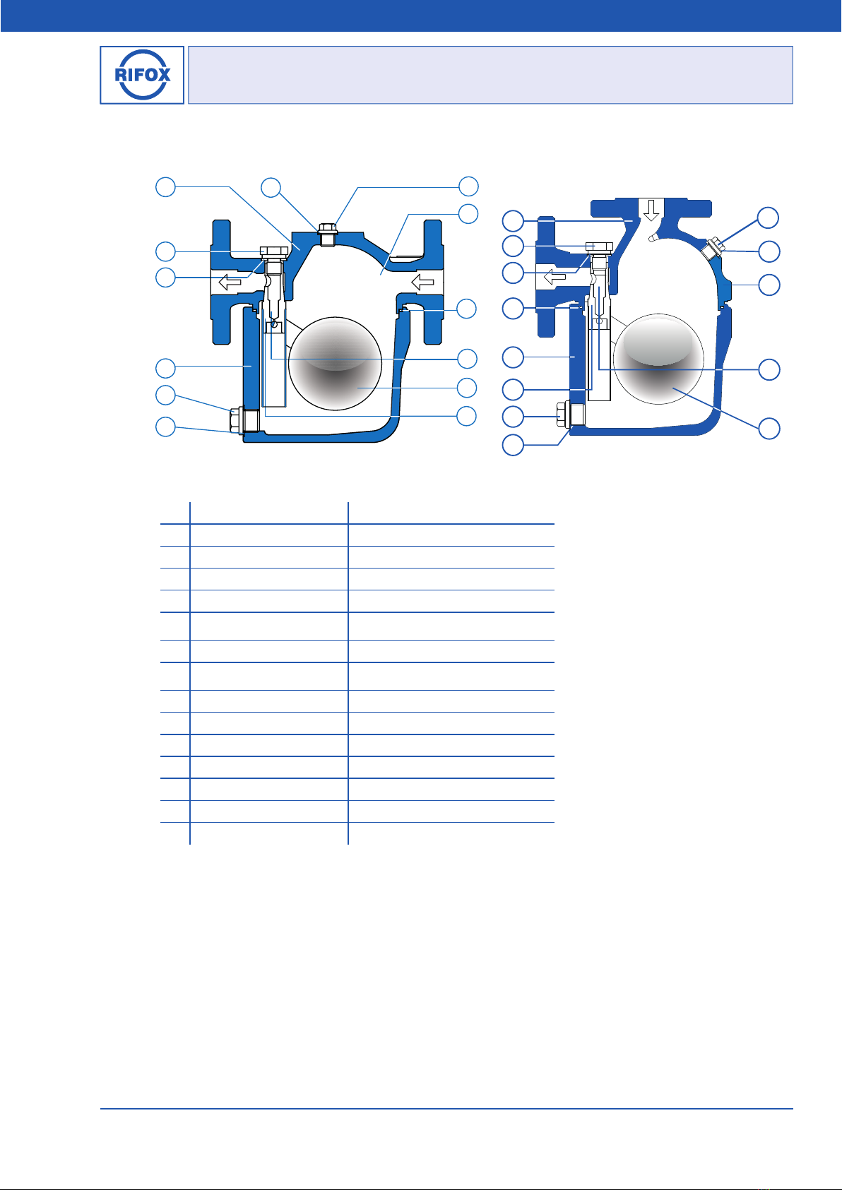
■Fitting direction: according to Picture 1 and 2.
■Supporting brackets: The supporting brackets are not necessary if the pipeline is adequately supported before and after
the condensate trap. The condensate trap weights from 10,5 to 27,5 kg, depending on the connection sizes.
■To avoid downtimes, it is recommended to install stop valves with bypass to pipeline, both in front of and behind the con-
densate trap.
4 Start-Up
Before commissioning, the valve closure (enclosed) must be screwed into the valve body. Otherwise the operating medium
can escape unhindered.
The pressure build-up and heating-up of the housing should not take place abruptly. If leakage is detected after the first
inspection, the screws (4 / 5 / 6 / 10 / 11) can be fixed under consideration of the given torque moments, as given in Section
6.5. The screws can only be tightened on when the housing is unpressurized and at room temperature.
5 Observation and control
The function’s failure can be observed either as condensate blockage or as gas/ steam leakage.
■Condensate blockage can be determined by a): loosen the control screw (4 or 11) for a quarter rotation, while no con-
densate leakage should occur; and by b): a surface thermometer on the housing for steam applications (if necessary, please
consult with Rifox).
■Gas / steam leakage: can be determined by an ultrasonic measuring device, and for steam applications by a surface
thermometer. In case of steam leakage, open the condensate trap according to Section 6.1. Make sure that float can be easily
moved. If necessary, disassemble and clean the float control assembly (7). If damages/ wears are detected on parts or on the
sealing surface, the complete float control assembly (7) should be replaced.
6 Maintenance / Inspection
6.1 Opening the steam trap and dismantling the float control
■The steam trap must be depressurized. Shut off the system securely in front of and behind the steam trap.
■Release any remaining pressure in the housing by loosening the control screw (4 or 11) by only a quarter turn.
■Loosen the housing screws (5) evenly crosswise. Put down the housing cover (1).
■Loosen the supporting screw (10) and unscrew it for 1 - 2 turns.
■With a few light strokes using plastic hammer on the front side of the supporting screw (10) to loosen the float control
assembly (7) from its conic housing seat.
■Screw out the supporting screw (10) completely. Remove the float control assembly (7).
6.2 Disassembling, cleaning and assembling the float control (Picture 4)
■After removing the cotter pin (p), the rotary valve (v) can be simply pulled out to the side.
■Clean the parts using, for example, benzine.

Operating Manual
Breite: 170
Höhe:8,15
Oben Links
278,5 20
RIFOX - Hans Richter GmbH Spezialarmaturen Fon: +49 (0) 421 499 75 - 0 Internet: www.rifox.de
Page 4 of 5
10/2020 -Di. Subject to modifications
■Check the rotary valve (v) for wear along the sealing edge. If wear is detected,
the support body (b) together with the rotary valve (v) must be replaced. The
thorough leakage test must be carried out by RIFOX.
■During assembly ensure that the notch in the rotary valve (v) points to the
punch mark on the support body (b) and the cotter pin (p) is inserted and secured
again carefully.
■It must be possible to move the float up and down easily by hand.
6.3 Installing the float control assembly and assembling the condensate trap
■The float control assembly (7) is inserted into the conical housing seat with
the supporting body. It must be ensured that the immersion tube is positioned
vertically downwards.
■ Screw in the installation bolt with copper gasket into the thread of the supporting body and tighten it with a wrench.
(Tighten torque see Sec. 6.5). Screw out the installation bolt, replace the copper gasket with a standard PTFE gasket (12).
■Screw in supporting screw (10) with gasket (12) and tighten it with a standard ring wrench. Tightening torque according
to Section 6.5.
■Check the housing gasket (2) and replace it if it is damaged.
■Tighten the hexagon bolts and nuts (5) evenly crosswise. Tightening torque according to Section 6.5.
6.4 Care and maintenance
■In the case of a great risk of dirt accumulation, the housing, when it is depressurized, should be rinsed thoroughly from
time to time. If necessary, the float control assembly (7) should also be checked according to section 6.2.
■The dirt, which has been accumulated in the housing, can be removed away by screwing out the screw plug (6).
■For special applications, it is advisable to install a separate upstream strainer.
■The float control assembly (7) usually does not to be special maintained. The maintenance depends primarily on the wear
resistance of the valve seat. See Section 6.1 and 6.2.
6.5 Tightening torque
Position Part Name
Tightening Torque (Nm)
DN15-25 DN40-50
1.4571 PTFE-special 1.4571 PTFE-special
4 Control valve, G¼“ 30 25 30 25
5 Housing screw 70 60 115 70
6 Screw plug, G½“ 100 55 100 55
10 Supporting screw 30* 25* 95 60**
11 Control screw, G¼“ 30 25 30 25
*Tighten the cone with a 60 Nm copper gasket in advance!
**Tighten the cone with a 90 Nm copper gasket in advance!
bpv
Picture 4

Operating Manual
Breite: 170
Höhe:8,15
Oben Links
278,5 20
RIFOX - Hans Richter GmbH Spezialarmaturen Fon: +49 (0) 421 499 75 - 0 Internet: www.rifox.de
Page 5 of 5
10/2020 -Di. Subject to modifications
6.6 Spare parts
Only original spare parts can be used.
13
4
5
2
7
9
8
12
6
3
10
114
11
14
7
9
5
1
3
2
13
6
10
12
8
Picture 5: Model 1101-N Picture 6: Model 1180-N
Pos. Part Name Material
01 Upper part of housing 1.4581 / 1.4408
02 Housing gasket PTFE-special or 1.4571
03 Lower part of housing 1.4581 / 1.4552
04 Control valve 1.4571
05 Set screw with nuts DN15-25: M 14 DIN 939/DIN 934, A4 – 70/A4
DN40/50: M 16 DIN 931/DIN 934, A4 – 70/A4
06 Screw plug 1.4571
07 Float control assembly 1.4571
08 Supporting body assembly 1.4571
09 Float 1.4571
10 Supporting screw 1.4571
11 Controll Screw 1.4571
12 Gasket PTFE-special or 1.4571
13 Gasket PTFE-special or 1.4571
14 Gasket PTFE-special or 1.4571
7 Conformity assessment
The pressure equipment described is a pressure-keeping component in accordance with the Pressure Vessel Directive
2014/68/EU.
DN15 / DN20 / DN25: according to Art. 4, Subs. 3, no CE-Mark.
DN40 / DN50: Conformity verified through the identifying mark: CE 0525.
A detailed declaration of conformity assessment according to PED is available as separate document. Please request if
necessary, if not attached.
This manual suits for next models
1
Table of contents
Other Rifox Fan manuals
Popular Fan manuals by other brands

Casablanca
Casablanca Campana owner's manual

Broan
Broan L100 Series instructions

ergovent
ergovent KVADRO-100 installation guide

Black & Decker
Black & Decker BDTF-4200R 120V AC 60HZ 55W instruction manual

Modern Forms
Modern Forms Smart Fans XF-SCK installation instructions

Soleus Air
Soleus Air FSM-40 operating instructions