Rioned Allround+ User manual

User’s Manual
Allround+
Edition: 05.1
Date: Saturday 11 November 2017
RIONED
P.O. Box 5070
5004 EB Tilburg
The Netherlands
Telephone: +31 13 5479100
e-mail: [email protected]
Internet: www.rioned.com

11/17 2
©Copyright 11/17 Rioned/RIOR B.V.Tilburg- Nederland.
All rights reserved. No part of this publication may be copied or published by means
of printing, photocopying, microfilm or otherwise without the prior written consent of
RIONED. This restriction also holds for the corresponding drawings and diagrams.
RIONED has the right to change parts of the machine at any time without any prior
or direct warning to the client. Similarly, the contents of this manual can also be
changed without any prior warning.
This manual is to be used only for this machine.
For extra information on adjustments, maintenance and repair, contact the technical
department of your dealer.

11/17 3
Foreword
This user’s manual is a manual for the professional user.
This user’s manual has the purpose to control the machine in a safety manner and
must be saved with the machine.
The photos and drawings help you understand the text easier.
First the user’s manual gives you an overview of the most important safety aspects.
Then we explain how the machine is built up and the global working of the machine.
Chapter “Technical specifications” gives you information about the working character-
istics, performance under normal use and construction specifications.
“Control” is the next chapter. This chapter explains how to use the machine system-
atically.
In the chapter “Maintenance”, the user can do small maintenance on the machine.
Chapter “Trouble shooting” has the purpose to solve simple defects.
With the “Exploded views” you can order original spare parts, are also useful for
mounting, and disassemble the machine.
Finally gives the chapter “Appendix” information about electrical and/or hydraulic
connections.

11/17 4

11/17 5
Table of Contents
1 Introduction...............................................................................7
1.1 Use......................................................................................7
2 Security......................................................................................9
2.1 Instruction indications in this manual........................................9
2.2 Descriptions security measures................................................9
2.3 Personnel protection outfit ......................................................9
2.4 Warnings..............................................................................9
2.5 Personnel qualification and education .....................................10
2.6 Danger that can occur if the security regulations aren’t observed10
2.7 Working safely.....................................................................10
2.8 Security regulations for the user and technical service ..............10
2.9 Security regulations for maintenance, inspection and mounting ac-
tivities................................................................................10
2.10 Making changes and fabricate spare parts ...............................10
2.11 Improper use ......................................................................10
3 Technical Specifications ...........................................................13
3.1 General .............................................................................13
3.2 Motor 230V ........................................................................14
3.3 Motor 110V ........................................................................14
4 Construction.............................................................................15
5 Control .....................................................................................17
5.1 Transport............................................................................17
5.2 Controls..............................................................................18
5.3 Lade verwijderen .................................................................20
5.4 Before unblocking ................................................................21
5.5 Unblocking..........................................................................24
6 Options.....................................................................................27
6.1 Foot switch .........................................................................27
7 Maintenance.............................................................................29
7.1 General ..............................................................................29
7.2 Cleaning the feed unit ..........................................................29
7.3 Lubrication..........................................................................33
7.4 Extensive periodical maintenance...........................................33
7.5 Maintenance schedule...........................................................34
8 Accessories ..............................................................................35
8.1 Supplies .............................................................................35
8.2 Auxiliaries that can be coupled: .............................................36
9 Exploded View
Explosionszeichnung und Ersatzteilliste
Dessin et Liste de Rechange.............................................................39

11/17 6
9.1 Exploded view .....................................................................40
9.2 Stuklijst..............................................................................41
9.3 Part list ..............................................................................42
9.4 Ersatzteilliste.......................................................................43
9.5 Liste de rechange.................................................................44
10 Appendix ..................................................................................45
10.1 EC declaration Of Conformity For Machinery ............................45
10.2 Sales Managers ...................................................................46
10.3 Dimensions.........................................................................47
10.4 Geluidsmeetrapport..............................................................48
10.5 Wiring diagram....................................................................49
10.6 Safety instructions ...............................................................50
11 Index .......................................................................................53

11/17 7
1 Introduction
RIONED wishes to thank you for your purchase of the RIONED drain and sewer-
clearing machine. We recommend that you read this manual thoroughly and
see that the machine is handled and maintained in the proper manner. If your
machine should give trouble and need servicing, when you want to order parts,
or if you have any questions, contact your RIONED dealer.
The machine is built by:
RIONED
P.O. Box 5070
5004 EB Tilburg
The Netherlands
Telephone: +31 13 5479100
e-mail: [email protected]
Internet: www.rioned.com
Your machine is specifically designed to clean drain- and sewer pipes with a di-
ameter from 40 mm to 125 mm by using specially manufactured cleaning
springs with a diameter of 16 mm diameter.
The machine may only be used by authorized personnel.
The machine can not be used in an explosive environment.
Fill the spring drum only with springs we describe in this manual.
In this manual you will find all necessary information concerning operations and
maintaining your machine. If handled properly, your machine is guaranteed ac-
cording the general delivery conditions.
1.1 Use
The main shaft is being driven by the electrical motor by means of chainwheel.
On this axle the spring drum is mounted. The drum contains the spring which
is to be lead into the drain or sewer opening. By means of the spring transport-
er and rotation direction the spring can be:
A Fed out of the drum.
B Fed into the drum.
C Kept in place.

11/17 8

11/17 9
2 Security
Be responsible for other people when you are working with this machine.
This manual contains instructions for fundamental conditions that must be fol-
lowed by use and maintenance of this machine.
That is why it is necessary that authorised and qualified personnel must read
the user's manual and the user’s manual must always be available with the ma-
chine. Near the general regulations in this chapter, you must also follow the se-
curity regulations in the other chapters.
2.1 Instruction indications in this manual
The in this manual containing security instructions, which are dangerous if they
are not obeyed, are marked with general security signs.
Security sign DIN 4844-W9
2.2 Descriptions security measures
•Stop
This machine is equipped with an stop. By operating the emergency
stop, the machine will stop. Also use it when dangerous situations oc-
cur. After use, remove the danger. Make sure the stop can always be
reached.
• Security covers
This machine is equipped with several security covers over parts that
are rotating. It is forbidden to remove these security covers during op-
erating this machine. You can only remove them if there is mainte-
nance on the machine. Stop the machine and take the plug out of the
wall socket.
• Spring guidance tube
The spring guidance tube protects you against the rotating spring. Now
your clothes can not get clamped between the spring openings.
2.3 Personnel protection outfit
• Protection looking glasses
•Gloves(Recommended)
• Dust cover (Recommended)
2.4 Warnings
Never take the spring when turning.
Do not let the spring turn outside ( swing of the spring).

11/17 10
Do not start the machine with switched in feed unit.
Take care of a stable disposition of the machine.
Never block the control lever, unless this is mentioned.
Do not wear cloth that hangs loose.
Please note safety instructions (See Chapter 9.5 "Safety instructions" page:
35).
Dust that arises when working on material containing asbestos or stonework
containing crystalline silicic acid is harmful to the health. Please follow accident
prevention regulations.
Do not pierce the motor housing as this could damage the double insulation
(use adhesives).
Keep mains lead clear from working range of the machine. Always lead the ca-
ble away behind you.
Never touch the spring if it is rotating. Not even with auxiliaries or other tools.
Never let the spring rotate outside a sewer, drain or pipe.
Never start the machine with the spring pusher downwards.
Never touch the spring if it is rotating. Not even with auxiliaries or other tools.
Never let the spring rotate outside a sewer, drain or pipe.
Make sure the machine is stable during operation.
Do not let the machine operate without supervision.
2.5 Personnel qualification and education
Personnel that use, maintain and inspect the machine must have the right qual-
ifications for this job.
Responsibility and authorisation of the personnel and the supervision on the
personnel must be embedded. If the knowledge is not present, the user must
provide for the necessarily education.
2.6 Danger that can occur if the security regulations aren’t observed
If the security regulations are not observed, danger can occur for personnel
and for the environment.
No amends are given if the regulations are not observed.
If the regulations are not observed, this can results in:
• Failure of important functions of the machine.
• Failure of prescribes methods for maintenance.
• Exposure of persons to dangers of electrical or mechanical failures
2.7 Working safely
The in this manual named security prescriptions, the national prescriptions to

11/17 11
prevent accidents and the internal labour, company and security prescriptions
must be followed by the user.
2.8 Security regulations for the user and technical service
• Protections of moving parts (for example couplings) may not be re-
moved if the machine is working.
• Leakage of dangerous mediums must disposed in a manner that there
is no danger for the personnel and environment. Statutory regulations
must be followed.
• Danger caused by electricity must be excluded.
2.9 Security regulations for maintenance, inspection and mounting activities
• The user sees to it that qualified technicians do all maintenance, in-
spection and mounting activities. They must study the manual thor-
oughly.
• Maintenance may only be done when the machine is not functioning
and the plug is out of the wall socket.
• The in the user’s manual mentioned handling to stop the machine must
be notified.
• Directly after maintenance of the machine, all the security and protec-
tion facilities must be functionally.
• Before starting the machine again, you must follow the instructions
correctly.
2.10 Making changes and fabricate spare parts
Changes to the machine are only permitted if Rioned has given written author-
isation. The use of original spare parts and accessories are for the safety nec-
essary. Rioned is not responsible for injuries or damages if other spare parts
are used.
2.11 Improper use
The security during working with the machine is only guaranteed if the use of
the machine is conform the user’s manual. The limits that are written in chapter
“Technical Specifications” and “Appendix” may never be overstept.
If the machine does not work or give troubles, it is forbidden to work further
with the machine. Telephone your dealer or the technical department of Rioned
Telephone: +31 (0) 13-5479100
This manual contains all the necessary information concerning control and
maintenance. If the device is positioned correctly, properly controlled, and reg-
ularly maintained, a warranty will be given according to the general conditions
of delivery. However, should it arise that the control and maintenance proce-
dures are not diligently followed, the warranty will become invalid.

11/17 12
11/17 13
3 Technical Specifications
3.1 General
Description (symbol) Unit
Type : Allround+
Dimensions : see chapter 10.3 Dimensions page.: 47
Weight (dry) (m) : 23,5 kg
Spring lengths (l) : 5 m, 10 m, 15 m and 20 m
Maximum spring length : 30 m
Spring diameter : 13 mm - 16 mm
Springs suitable for sewer diameter : 40 - 125
Place type plate:
Place frame number:
In and out speed spring : 0 - 8 m/min
Rotation direction : Left and right
RPM drum : 195 r.p.m.
Year of construction (month/year) :Seetypeplate
J

11/17 14
3.2 Motor 230V
Description (symbol) Unit
Mark/Type : Neri
Power (P) : 250 W
Revolutions : 1450 r.p.m.
Voltage and frequency : 230 V, 50 Hz.
Security : Thermal
Cos :0,94
Isolation class : IP 54
3.3 Motor 110V
Description (symbol) Unit
Mark/Type : Neri
Power (P) : 250 W
Revolutions : 1660 r.p.m.
Voltage and frequency : 110 V, 60 Hz.
Security : Thermal
Cos :0,94
Isolation class : IP 55


11/17 16
11/17 17
5Control
If you control, maintain or inspect the machine, you must have
the right qualifications for this job. If you do not have the
necessarily knowledge, you may not use the machine. Further,
you must convince yourself that you understand this manual
thoroughly.
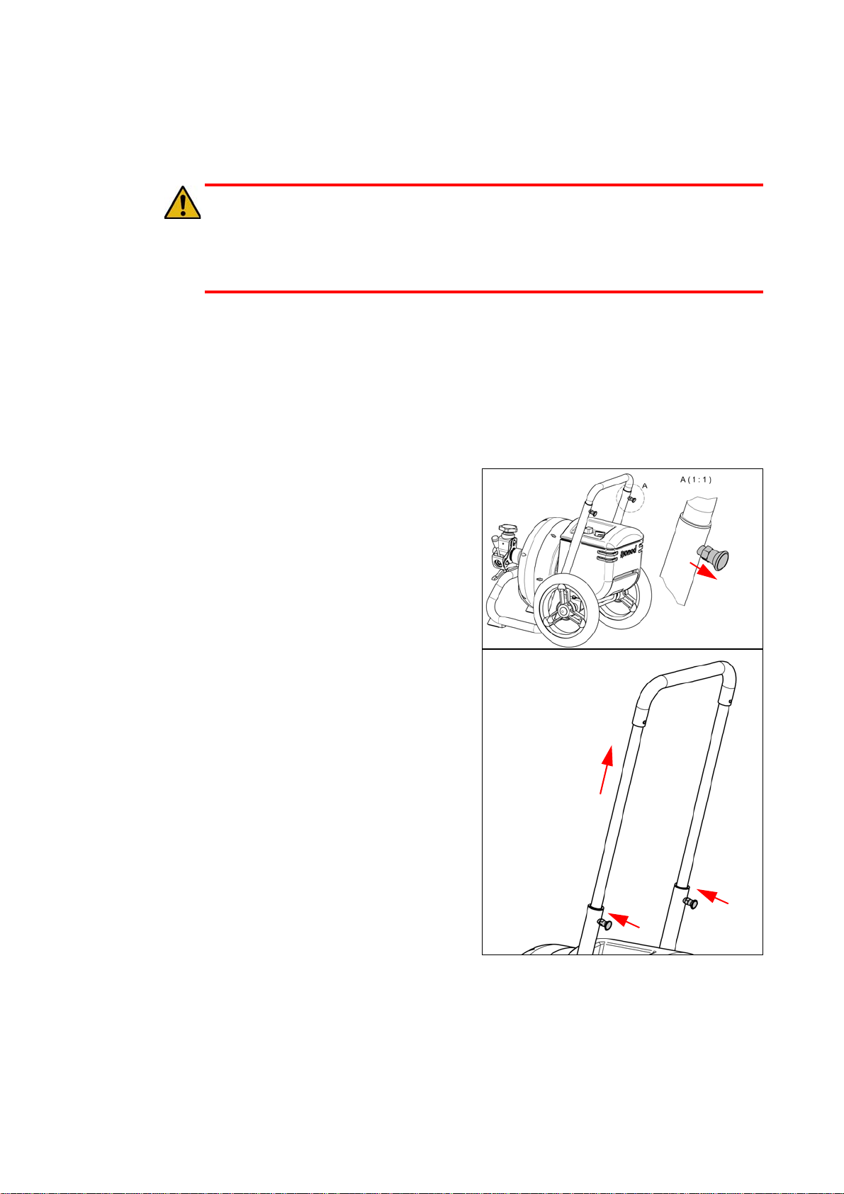
5.1 Transport
1. Pull the plug out of the wall socket.
2. Wind the wire around the bow.
3. Couple the extra spring loose and put in storage.
4. Transport the standard spring in the drum.
5. Let the standard spring reach a little bit out of the feed unit.
6. Pull the knobs of the bow
loose (2x).
7. Pull the bow completely out
of the frame.
8. Lock the bow again.
9. Overturn the spring machine
by means of the bow.
10. Now you can move the spring
machine.
11/17 18
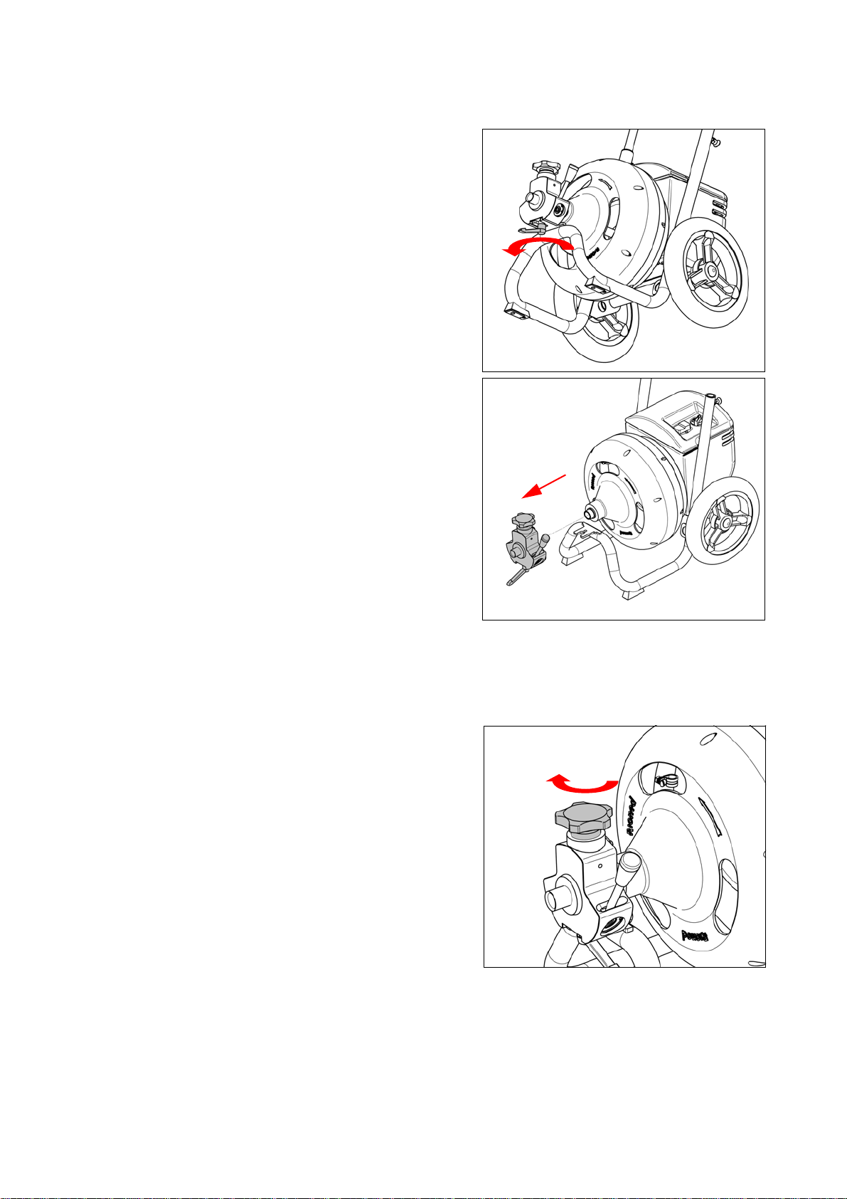
5.2 Controls
1. Clamp handle:
Turn the handle a quarter
turn loose to dismount the
feed unit.
2. Pressure knob:
By turning the pressure knob, you can bring the feed unit in and out
of order.
a Turn pressure knob
clockwise:
Feed unit activated.
Spring rotates and gets
transported.

11/17 19
b Turn pressure knob
counter clockwise:
Feed unit out of order.
Spring rotates, no
transportation.
3. Switch:
Position : no rotation.
Position : drum rotates in
working direction.
Position : drum rotates
reverse. First push the plate
lock (A), then turn the switch
further over the plate. Use
this position to get a jammed
spring back.
4. Press button “Green”:
With this button, the motor
starts. The drum begins to
rotate in the chosen direc-
tion.
5. Press button “Red”:
By operating the stop, the
machine will stop. Also use it
when dangerous situations
occur.
Make sure the stop can al-
ways be reached.
A

11/17 20
6. Feed unit handle:
By operating this handle, the
transportation ofthe spring is
controlled.
a Lever maximum point-
ing to the drum:
Spring transport speed
maximum in.
b Lever maximum from
the drum off:
Spring transport speed
maximum out.
c Lever in the middle:
no transport.
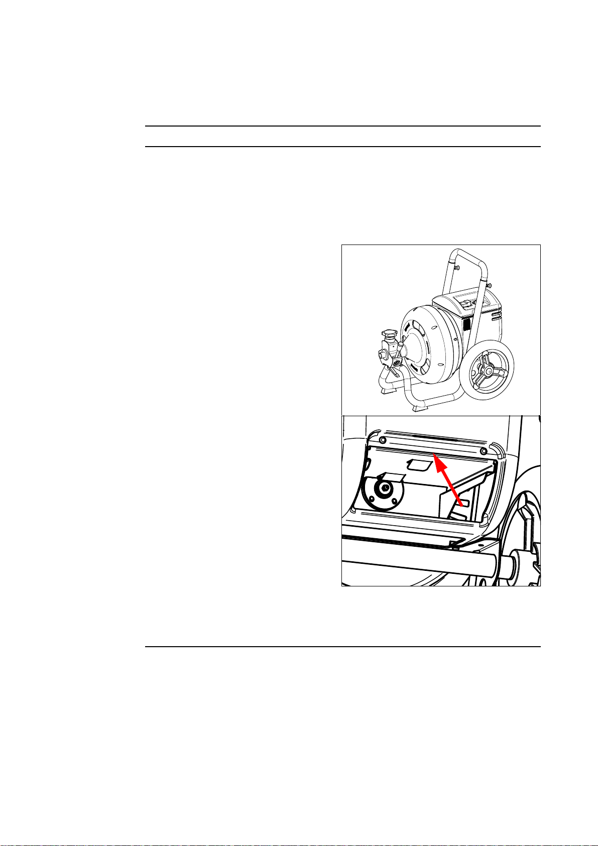
7. Drawer with accessories
5.3 Lade verwijderen
1. Lade open schuiven
2. Lip indrukken
3. Lade uitnemen
Table of contents


