Ritron LPA-U450 User manual

LPA-Series Owner’s Manual
Ritron Pub. 14500062 Rev. A 10/07
© 2007 Ritron, Inc. All rights reserved. Ritron, Patriot, Jobcom, OutPost, GateGuard, Quiet Call and
Quick Assist are registered trademarks of Ritron, Inc. Loudmouth, Quick Talk, Liberty and RadioNexus
are trademarks of Ritron, Inc.
Call 800-USA-1-USA
For the right Wireless Solutions for your communication needs.
P.O. Box 1998 ·Carmel, Indiana 46082-1998 · 317-846-1201 · Fax: 317-846-4978
Email: [email protected] · www.ritron.com


Table of Contents
1Getting Started
1.1 LPA-Series receiver assembly.............................................................................................................. 2
1.2 Paging the LPA-Series receiver............................................................................................................ 3
1.3 Compatibility with other RITRON model radios .................................................................................... 4
2Installation
2.1 Radio coverage site survey .................................................................................................................. 5
2.2 LPA-Series radio receiver installation................................................................................................... 8
2.3 LPA-Series AUX IN installation............................................................................................................. 9
2.4 LPA-Series 600ΩBALANCED installation ......................................................................................... 10
3Programming
3.1 LPA-Series Field Programming Overview .......................................................................................... 11
3.2 Readout Current Frequency, Tone and Selective Signaling Codes.................................................... 12
3.3 Program Frequency & Tone Codes .................................................................................................... 13
Table 1: Programmable Frequency Codes ................................................................................. 14
Table 2: Interference Eliminator Programmable QC Tone Codes............................................... 14
Table 3: Digital Interference Eliminator Programmable DQC Tone Codes ................................. 14
3.4 Program Paging Codes ...................................................................................................................... 15
Table 4: 2-Tone Paging Codes ................................................................................................... 15
3.5 Program LPA-Series Features............................................................................................................ 16
Table 5: Feature Codes .............................................................................................................. 16
3.6 Program LPA-Series Volume.............................................................................................................. 17
Checking the current volume setting............................................................................................... 17
3.7 Program the NOAA Weather Frequency ............................................................................................ 18
Table 6: NOAA Weather Frequency Codes ................................................................................ 18
4Operation
4.1 Basic Operation .................................................................................................................................. 19
4.2 Selcall Paging..................................................................................................................................... 19
4.3 2-Tone Paging .................................................................................................................................... 20
4.4 Record and Play ................................................................................................................................. 20
4.5 Weather Alert...................................................................................................................................... 21
4.6 Battery Powered Operation ................................................................................................................ 21
4.7 LPA-Series Options ............................................................................................................................ 22
4.8 How to Minimize Feedback ................................................................................................................ 22
5Specifications
5.1 General............................................................................................................................................... 23
5.2 RPS-1A Power Cube.......................................................................................................................... 23
5.3 LPA-Series Receiver .......................................................................................................................... 24
Field Programming Map ..................................................................................................................... 25
6Warranty ................................................................................................................................................. 26
1 Getting Started
The LPA-Series receiver is designed for interface to existing wired Public Address
systems to allow PA announcements using VHF or UHF business band, FRS, or
MURS radios.
Major Benefit: The LPA receiver allows all the wired speakers in a PA/Intercom system immediately accessible via a
2-way radio/base station/ etc. The LPA receiver can be connected to an existing wired system. An
LM and LPA receiver system can be used side-by-side on the same frequency.
What is The Difference b/w The LM-V150/U450 Receiver and The LPA-V150/U450 Receiver?
•The LM Receiver (#LM-V150/U450) has a built-in audio amplifier. The built-in audio amplifier allows the LM receiver
by itself to drive up to 2 Ritron PA horn speakers. The LM receiver and included PA Horn speaker is what we call a
stand-alone wireless PA system.
•LPA Receiver (#LPA-V150/U450) does not have a built-in PA amplifier. The LPA receiver is designed to be
connected to an existing PA/intercom system with its own PA amplifier and wired speakers.
•The LPA receiver does not include a back-up battery since it is merely a component of a larger system usually
powered by AC and its own battery back-up system.
Features/Benefits:
•Available in VHF (150-162 MHz) and UHF (450-470MHz) frequency bands. Provides compatibility with business
band 2-way radios, License-FREE VHF business band radios (MURS), Family Radio Service and GMRS radios.
•Provides interconnection to the Public Address amplifier through a high impedance, unbalanced AUX input OR a
600Ω, balanced MIC input. Allows personnel to remain mobile while providing access via 2-way radio access to
existing PA speakers located throughout the facility.
•If the AUX input of the PA/Intercom amplifier is already used (ie: stereo tuner for background music) the LPA-
Series is installed in-between the audio source (stereo tuner) and the PA/Intercom amplifier. When the LPA-Series
receives a message the audio source is interrupted and the received message is sent to the PA/Intercom amplifier
instead.
•“Record and Play” allows use of radios in close proximity to PA speakers without feedback. The LPA-Series
records/buffers received messages up to 30 seconds in length, then plays them over the PA immediately after
releasing the PTT button on the radio.
•Easy “Plug and Play” installation.
•Programmable volume control adjusts
audio output level 5-99%. Allows custom
adjustment for most applications.
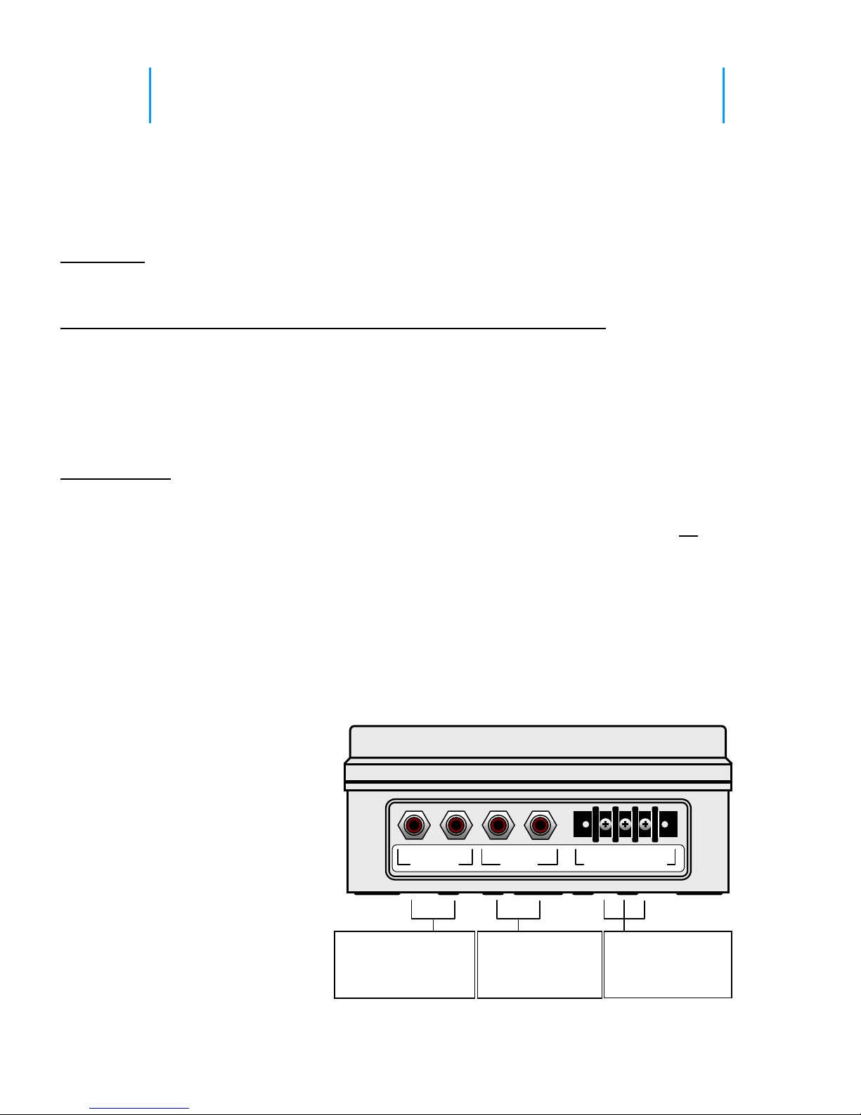
AUX OUT connects to
the high impedance,
unbalanced AUX input
of the PA amplifier.
If used, a CD player,
tuner or tape player
connects to AUX IN
600ΩBALANCED
connects to the
600Ωbalanced input
of the PA amplifier.
L R
AUX IN
HOT GND COLD
600ΩBALANCED
L R
AUX OUT
•Selective signaling includes QC, DQC,
Selcall, 2-Tone to provide an added layer
of access control to the PA system.
•Pre-announce tone (similar to existing PA
systems) with programmable on/off and
volume level.
•NOAA Weather Alert (VHF only).
•Field or PC programmable to frequencies
within the respective band (i.e. 150-165
MHz, 450-470 MHz).
•The LPA-Series is for interface only to an
existing PA system, it cannot drive a
loudspeaker by itself.
•The LPA-Series is for indoor use ONLY.
Section 1 Getting Started 1

1.1 LPA-Series receiver assembly
The LPA-Series receiver is on any time power is applied. The receiver case must be opened to install the
Mounting Bracket or to program the LPA-Series receiver.
Section 1 Getting Started 2
1. Loosen the (4) captive screws in the front corners of the case. These screws are captive to the housing; to
prevent damaging them, DO NOT remove the screws from the housing.
2. Separate the case front from the case back.
3. Install the Mounting Brackets by inserting the 4 sealed screws included in the Mounting Bracket kit into the
4 pre-drilled holes shown above. Secure the Mounting Brackets to the case using the lockwashers and nuts
included in the Mounting Bracket kit.
4. Program the LPA-Series receiver per the instructions in the Programming section of this manual, leaving the
RPS-1A power supply connected to the radio. Press the Enter button twice before re-assembling the case to
be sure the LPA-Series receiver is reset and ready for operation.
5. Carefully position the case front onto the case back. Secure the case halves by tightening the 4 captive
screws in the front corners of the case.
PROGRAMMING
Enter Button
Program Display
Program Button
RJ-11 Program
Cable Connector
DC Power Connecto
r
for RPS
-
1A
RCA Phono Jacks
For AUX IN and OUT
BNC Antenna Connector
for AFB
-
1545
Pre-drilled holes for
Mounting Bracket (4 corners)
Captive Plastic Case
Screws
(
4 corners
)
Barrier Strip
For 600Ω
Balanced Output

1.2 Paging the LPA-Series receiver
The LPA-Series receiver can be paged with 2-way radios programmed for Quiet Call (CTCSS), Digital Quiet Call
(DCS), 2-Tone Paging, or Selcall paging formats. Each format offers a unique method of paging the LPA receiver.
Refer to the Programming section of this manual for specific instructions on programming your LPA receiver to one
of these selective signaling formats.
Section 1 Getting Started 3
Ritron strongly recommends operation of the LPA-Series receiver with one
of the following selective signaling formats enabled.
Paging the LPA-Series receiver with Quiet Call (CTCSS) only:
•To page the LPA receiver a user simply presses the 2-way radio’s PTT and speaks while on the LPA
channel.
•Your 2-way radio must be programmed for a channel dedicated to LPA receiver operation. Only those
radios programmed with the LPA channel will be able to access the loudspeaker.
•The 2-way radio’s LPA channel and the LPA receiver must be programmed for the same QC code. All
Ritron radios offer 50 different field-programmable QC codes from which to choose.
Paging the LPA-Series receiver with Digital Quiet Call (DCS) only:
•To page the LPA receiver a user simply presses the 2-way radio’s PTT and speaks while on the LPA
channel.
•Your 2-way radio must be programmed for a channel dedicated to LPA receiver operation. Only those
radios programmed with the LPA channel will be able to access the loudspeaker.
•The 2-way radio’s LPA channel and the LPA receiver must be programmed for the same DQC code.
All Ritron radios offer 104 different field-programmable DQC codes from which to choose.
Paging the LPA-Series receiver with 2-Tone Paging:
•To page the LPA receiver the 2-way radio must first send the correct 2-Tone Paging code. Once
access to the LPA receiver is accomplished, the user simply presses the 2-way radio’s PTT and speaks
while on the LPA channel. After a period of inactivity the LPA receiver is automatically reset, and will
then require the correct 2-Tone Paging code to re-gain access.
•Only 2-way radios programmed to send the correct 2-Tone code on the LPA channel can access the
LPA receiver. However, once access is gained, any 2-way radio that operates on the LPA channel can
access the LPA receiver up until the time that the LPA receiver has automatically reset.
•Can be used in conjunction with QC or DQC for added security. The 2-way radio and the LPA receiver
must be programmed for the same QC or DQC code.
Paging the LPA-Series receiver with Selcall:
•To page the LPA receiver the 2-way radio must be programmed to send the correct Selcall code every
time the PTT is pressed. The user simply presses the 2-way radio’s PTT and speaks while on the LPA
channel.
•Only 2-way radios programmed to send the correct Selcall code on the LPA channel can access the
LPA receiver.
•Can be used in conjunction with QC or DQC for added security. The 2-way radio and the LPA receiver
must be programmed for the same QC or DQC code.

Ritron recommends the use of a dedicated channel frequency for LPA
operation.
When operating on unique frequencies dedicated to LPA operation:
•Your 2-way radios must be programmed for a channel dedicated to LPA operation.
•LPA-Series receiver operation is limited to radios programmed with the dedicated LPA channel.
•The use of 2-tone or Selcall paging to address the LPA receiver is not required, but can still be used if
additional access security is desired.
•Without 2-tone or Selcall paging the LPA receiver can be addressed by simply selecting the LPA
channel on your 2-way radio and pressing the PTT button to talk.
•You may need to license additional frequencies (not necessary with LPA-V150 programmed for MURS
frequencies, see Table 1 in the Programming section).
When operating on your normal 2-way communication frequencies:
•Messages received by the LPA-Series receiver and broadcast on the wired PA system are also heard
on your 2-way radios.
•LPA operation is not possible when the channel is being used for 2-way communications.
•The use of 2-tone or Selcall paging is required to address the LPA receiver, otherwise all 2-way
communication is heard on the wired PA system.
•Any user on your 2-way channel can broadcast over the wired PA system once the LPA receiver is
activated, even if their 2-way radio is not programmed with the correct 2-tone paging code.
•There is no need to license additional frequencies.
Section 1 Getting Started 4
1.3 Compatibility with other RITRON model radios
The LPA-Series receiver is available in both VHF (LPA-V150, 150-165 MHz) and UHF (LPA-U450, 450-470 MHz)
business band frequencies. LPA receivers can be accessed with radios programmed for Quiet Call (CTCSS),
Digital Quiet Call (DCS), 2-Tone Paging, or Selcall paging formats. The following chart can be used to determine
compatibility with existing Ritron radios.
VHF models compatible with LPA-V150 UHF models compatible with LPA-U450
2- 2-
Model Type QC DQC Tone Selcall Model Type QC DQC Tone Selcall
JMX-141D Portable √JMX-441D Portable
√
JMX-144D Portable √√√JMX-444D Portable
√√√
JMX-146D Portable √JMX-446D Portable
√√√
JBS-146D Base √√√JBS-446D Base √√√
* J-V110 Portable √√√* J-U410 Portable
√√√
RPM-160 Mobile √√√√RPM-460 Mobile √√√√
RQX-151 Callbox √√RQX-451 Callbox
√√
RQX-156 Callbox √√√RQX-456 Callbox √√√
RQX-157 Callbox √√√RQX-457 Callbox √√√
SLX-100 Portable
√√√√SLX-400 Portable √√√√
*2-Tone paging available with Rev 6 Firmware Only. See label inside radio battery compartment for
firmware revision.
2 Installation
Proper installation of the LPA-Series receiver is critical to the performance and
overall satisfaction with your system. With careful consideration and planning the
LPA-Series can receive a radio signal from up to a mile away and broadcast it over
your wired PA system. This section will help you plan an installation that is best
suited for your environment.
2.1 Radio coverage site survey
Ritron recommends that you do a “radio coverage site survey” before
permanently installing the LPA-Series receiver.
This will require 2 people and 2 charged portable radios.
Every building is different, and therefore, no “single” rule applies when it comes to where to install the LPA receiver
and antenna for optimal coverage. Ideally, you would like to install the LPA-Series receiver in close proximity to
the wired PA amplifier for easy installation. Begin your site survey by locating person #1 at the wired PA amplifier
to see if a simple installation is possible. If that is not possible, an alterative site must be found where:
1. AC power is available for the LPA receiver.
2. A shielded, twisted pair cable can be routed from the LPA receiver to the PA amplifier.
In general, the antenna of the LPA receiver is the “pivot” point for all communication. We’re trying to optimize the
location of the antenna in order to reduce the obstructions and distance the radio signal must travel in order to get
from any point in the desired coverage area to the antenna connected to the LPA receiver. By attempting to install
the ANTENNA for the LPA receiver “in the center” of the desired coverage area, we reduce the distance the radio
signal must travel by ½. If you’re attempting to cover a high rise building (e.g. 15 floors), go to a location half way
up (e.g. 7th floor), and in the center of the building.
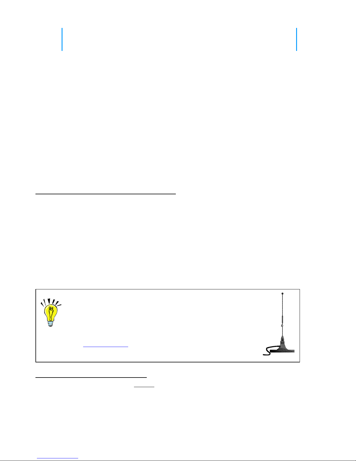
Radio range can be extended with the use of an external
antenna.
The antenna can be installed at a higher elevation than is possible with the
attached antenna.
The Ritron RAM-1545 VHF/UHF magnet-mount antenna has a 25 ft.
cable to allow optimum antenna location.
Preparing for the radio coverage site survey:
1. Charge the radio batteries for at least 12 hours.
2. When charged, make sure both radios are set to the same channel.
Note: If you do not intend to route LPA communications through a repeater, the portable radios should be set to
a channel programmed for direct radio-to-radio communication, NOT through the repeater.
Section 2 Installation 5
Conducting the radio coverage site survey:
1. Person #1 will take one portable radio and go to the location you would “most likely” install the antenna for the
LPA receiver (see FIG-2). This person will “simulate” the type of coverage you can expect, IF, the antenna for
the LPA receiver was installed in this location. If necessary, position this person on a ladder to more
accurately mimic the height you intend to mount the antenna.
BE ADVISED – you may have to try several heights and/or locations before settling on the best location.
2. While person #1 remains stationary, person #2 will take the second radio and “walk the site”. While “walking
the site” person #2 must attempt to maintain radio contact periodically with person #1. This survey process will
reveal whether or not radio coverage is acceptable IF you install the antenna at the person #1 location.
Generally speaking, coverage will be slightly better when the LPA receiver and antenna are permanently
installed.
3. If coverage is inadequate, Person #1 will need to relocate to a new location and repeat the process until range
and coverage are optimized.
Hints: Typically, the higher the antenna the better but, NOT always. Every site is different. Thick, reinforced
concrete, steel walls and vertical fire panels in ceilings can work to block the penetration of radio signals
creating dead spots. You may want to gradually lower the height of the antenna and/or its location and repeat
your site survey to see if coverage improves. It is best to change one variable at a time e.g. antenna height,
location and then repeat the process.
4. For sites where coverage is desired in multiple buildings, such as an office complex, an external mounted
antenna may be required. Before considering an external installation of the antenna, a site survey should be
attempted with person #1 positioned inside a centrally located building at the highest possible elevation (see
FIG-3). Person #2 will “walk the site”, communicating with person #1 from inside all buildings and at all
outside areas where radio coverage is desired.
Section 2 Installation 6
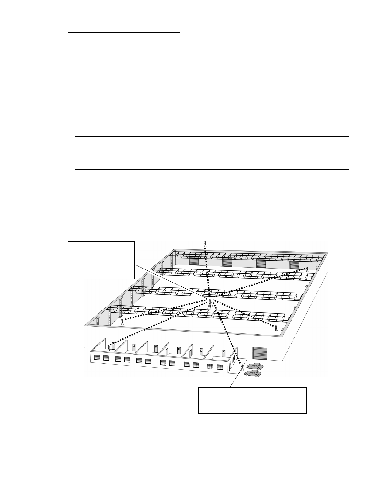
FIG-2: Conducting a radio site survey
Person #2 “walks the site”, stopping
frequently to communicate with person
#1 at the fixed, central location.
2
2
2
2
2
2
Person #1 remains at the
location you will install the
LPA receiver, possibly on
a ladder to simulate the
location of an external
mounted antenna.
Section 2 Installation 7
Person #1 remains in a
fixed location, probably
located on a floor about
½ way up the building.
Person #2 “walks the site”,
stopping frequently on each
floor to communicate with
person #1 at the fixed location.
2
2
2
2
2
2
Alternative
locations for
person #1
Alternative locations
for person #1
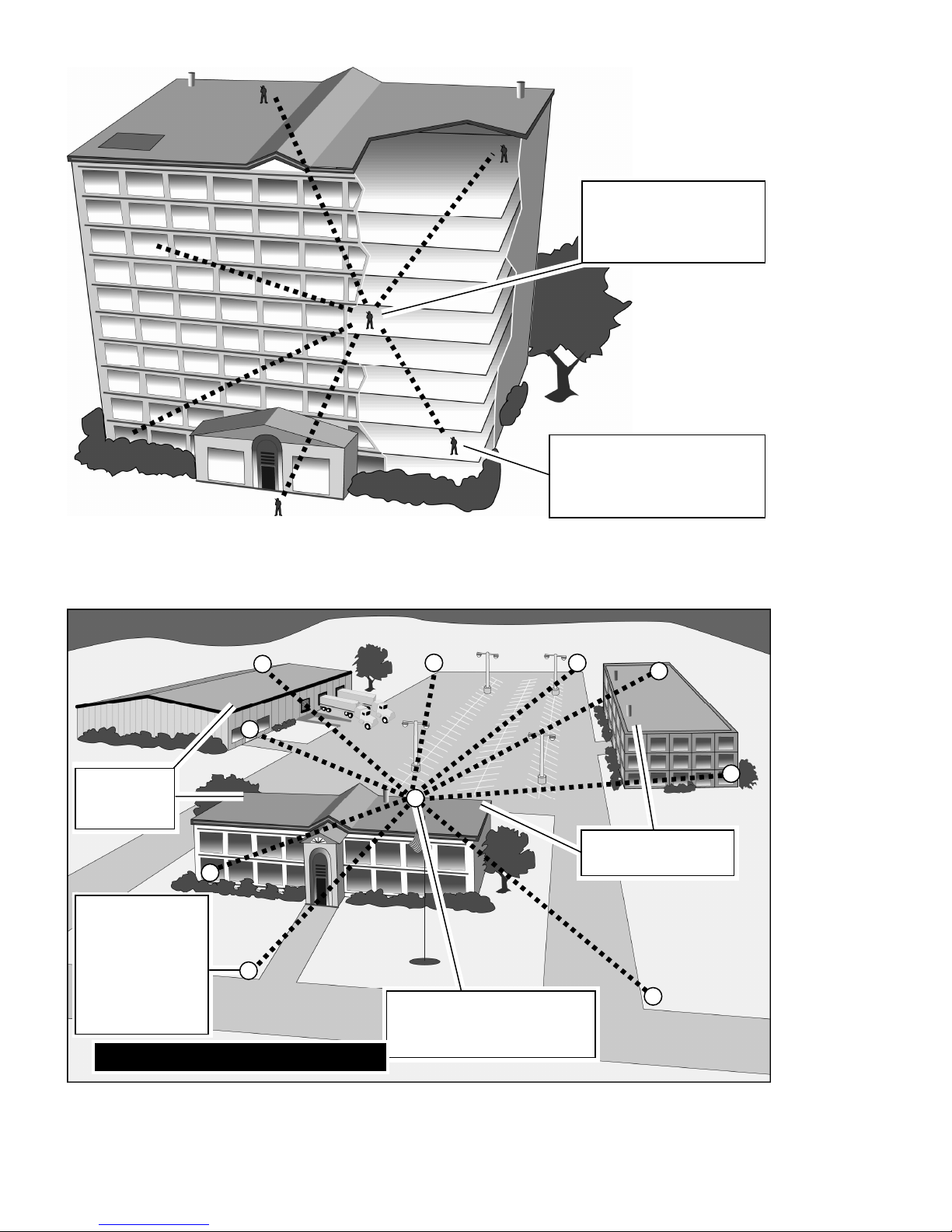
Person #1 remains in a fixed
location on the top floor of a
centrally located building.
FIG-3: Multiple building site survey
2
2
22
2
2
2
2
1
Person #2 “walks
the site”, talking
to person #1
from within each
building and from
the perimeter of
the outside
covera
g
e area.
2

Installing a Magnetic Mount Antenna for the LPA-Series Receiver
A magnetic mount antenna should be installed in a location, which is at, or as close as possible to the best location as
determined by the site survey. The antenna’s magnetic base must be attached to a piece of metal (i.e. steel or iron).
The antenna comes with 12 feet of attached co-axial cable* so you can remotely locate the antenna up to 12 feet away
from the LPA-Series receiver. The antenna cable MUST run directly away from the LPA receiver.
* Do NOT attempt to cut, shorten or splice this cable in any way.
For best performance the magnetic mount antenna must be:
• Mounted on a metal surface e.g. steel or iron. This metal mounting surface MUST be at least 2 feet square with
the antenna positioned in the center. The antenna’s internal magnet will secure it to the surface. Do NOT place
adhesives between the bottom of the antenna mounting surface and the metal mounting surface itself.
• Orient the antenna so that the element itself is vertical. The antenna can be mounted upside down with no affect
on performance. Just make sure the antenna element is vertical.
• Mounted away from other metal objects, walls, and structures. Avoid surrounding the antenna or “shielding” it by
locating it too closely to metal walls, inside an elevator shaft, in recessed girders, firewalls or ceilings.
Section 2 Installation 8
2.2 LPA-Series radio receiver installation
Installation of the LPA receiver is critical to the effective radio coverage of the radio PA
system. Without proper installation the maximum possible distance between the calling
radio and the LPA receiver will be significantly reduced.
Guidelines for installing the LPA-Series receiver:
•The radio receiver box must be located inside, out of the elements.
•For best radio coverage the LPA receiver should be installed in a central
location and as high up as possible.
•For maximum radio coverage the antenna should be in a vertical orientation
and should not be touching or surrounded by large metal objects. The receiver
box can be mounted horizontally as long as the antenna is in a vertical
position.
•Do not install the LPA receiver in a high traffic location with the possibility that
the receiver box would be struck, become unplugged, or disconnected from the
PA amplifier.
L
o
u
d
M
o
u
t
h
L
o
u
d
M
o
u
t
h
•If connection to the PA amplifier is via it’s AUX IN, the
LPA receiver must be within 6 ft. of the PA amplifier.
•Do not wind, loop or otherwise allow the power cord from the RPS-1A
power cube to contact the antenna. The power cord should be routed
away from the antenna.
•Be sure there is a convenient source of 110VAC power for the RPS-
1A power cube.
RPS-1A
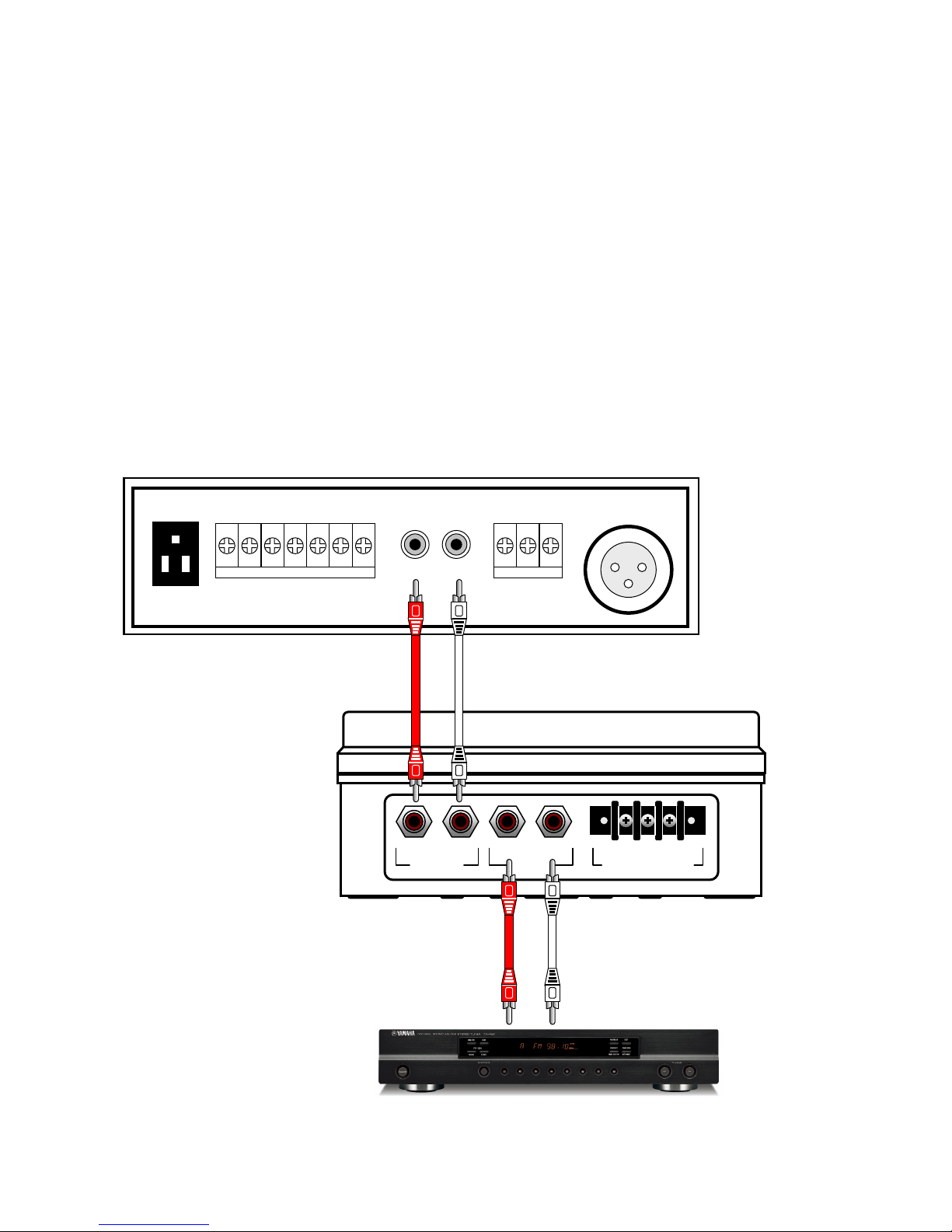
2.3 LPA-Series AUX IN installation
The LPA-Series receiver can connect to the AUX INPUT of a public address
amplifier if the LPA receiver is installed in close proximity to the PA amplifier.
•The RCA phono cables required for interconnection should be no longer than 6 feet. Installations requiring
LPA receiver location greater than 6 feet from the PA amplifier must use the 600Ωbalanced output.
•If the AUX INPUT of the PA amplifier is already used, the LPA receiver is connected between the AUX audio
source (stereo tuner, cd player, tape player, etc.) and the PA amplifier as shown.
•Audio from the AUX audio source will be routed to the PA amplifier as normal when the LPA receiver is not
in use. When an LPA radio message is received, the LPA receiver will disconnect the AUX audio source
and replace it with the radio transmission. Once the radio message is complete the AUX audio source is re-
connected to the PA amplifier.
•When using the PA amplifier AUX INPUT it is important to remember that received messages from the LPA
receiver will be treated exactly the same way any other audio device connected to the AUX INPUT. On
many PA amplifiers the AUX INPUT audio is automatically muted whenever audio is present on the MIC
INPUT. Check the owner’s manual for the PA amplifier to determine AUX INPUT operation and the effect it
will have on LPA operation.
600
Section 2 Installation 9
RCA PHONO CABLES
6 FT. MAXIMUM
RCA PHONO CABLES
STEREO TUNER
PUBLIC ADDRESS AMPLIFIER
(REAR PANEL)
Ω
MIC-1
GND COM HOT
600
Ω
MIC-2
SPEAKER A
U
X INP
U
COM 4Ω8Ω16ΩCOM 25V 70V
T
L R
UNSWITCHED
L R
AUX IN
HOT GND COLD
600ΩBALANCED
L R
AUX OUT
LPA-SERIES RECIEVER
(SIDE PANEL)

2.4 LPA-Series 600ΩBALANCED installation
The LPA-Series receiver can be connected to the 600Ωbalanced MIC INPUT of
a public address amplifier when the LPA receiver is not located close to the PA
amplifier.
•When an LPA radio message is received, the LPA receiver will send the audio to the 600 Ωmicrophone input
of the PA amplifier.
•A typical balanced cable contains two identical wires, which are twisted together and then wrapped with a third
conductor (foil or braid) that acts as a shield. The wires are twisted together, to reduce interference from
electromagnetic induction. Twisting makes the loop area between the conductors as small as possible, and
ensures that a magnetic field that passes equally through adjacent loops will induce equal but opposite
currents, which cancel out. The separate shield of a balanced audio connection also yields a noise rejection
advantage over an unbalanced two-conductor arrangement (such as AUX IN) where the shield must also act
as the signal return wire. Any noise currents induced into a balanced audio shield will not therefore be directly
modulated onto the signal, whereas in a two-conductor system they will be. This also prevents ground loop
problems, by separating the shield/chassis from signal ground.
NOTE: To minimize noise it is often necessary to connect the ground shield at only one end of the cable.
Section 2 Installation 10
LP
A
PA Amp
HOT connects to HOT or “+” or POS
COLD connects to COLD or “-“ or NEG or COM
GND connects to GND or CHASSIS or
600
Ω
MIC-1
PUBLIC ADDRESS AMPLIFIER
GND COM HOT
600 Ω
MIC-2
SPEAKER A
U
X INP
U
COM 4Ω8Ω16ΩCOM 25V 70V
T
L R
UNSWITCHED
SHIELDED,
TWISTED PAIR
L R
AUX IN
HOT GND COLD
600ΩBALANCED
L R
AUX OUT
LPA-SERIES RECEIVER

3 Programming
For most installations the LPA-Series receiver can be programmed in the field
without the need for Ritron PC Programmer 12.0.1. Field programming is
accomplished in 3 easy steps. First, the radio frequency and tone codes are
entered. Second, the selective signaling code is entered (if used). Third, the LPA-
Series options and volume setting are entered.
3.1 LPA-Series Field Programming Overview
Press ENTER
Section 3 Programming 11
Program
odes
CTable Codes
Enter a 2-digit Frequency code from Table 1 and a 2-digit QC code from Table 2 or
nter a 2-digit Frequency code from Table 1 and a 3-digit DQC code from Table 3.
E
or
Enter a 2-digit, 2-Tone Paging code from Table 4
Enter any 3 – digit Selcall Paging Code.7-
E rnte a 2-digit Feature code from Table 5 to:
•Enable or disable a Pre-Announce Tone.
•Enable or disable Record and Play operation.
•Enable or disable Weather Alert feature (VHF models only)
•Reset LPA-Series receiver to Factory default programming.
Enter the desired Speaker Volume Level as a 2 –digit number from 05 – 99.
Enter the 1-digit NOAA Weather Frequency code from Table 6 (VHF models only)
This only programs the NOAA weather frequency, the Weather Alert feature must be enabled using
the Special Features code in Table 5.
Place the
LPA-Series
receiver
into
Program
mode.
Use PROGRAM
button to scroll to
one of the following
Program Code
characters:
[F], [C], [A], [U], [d]
Pause, a
hyphen
will
appear
on the
display.
Using the
PROGRAM
button to save
programming entry.
button,
enter the
desired
Table Code. Press ENTER button a second
time to Exit programming.
or
Proceed with next program entry.

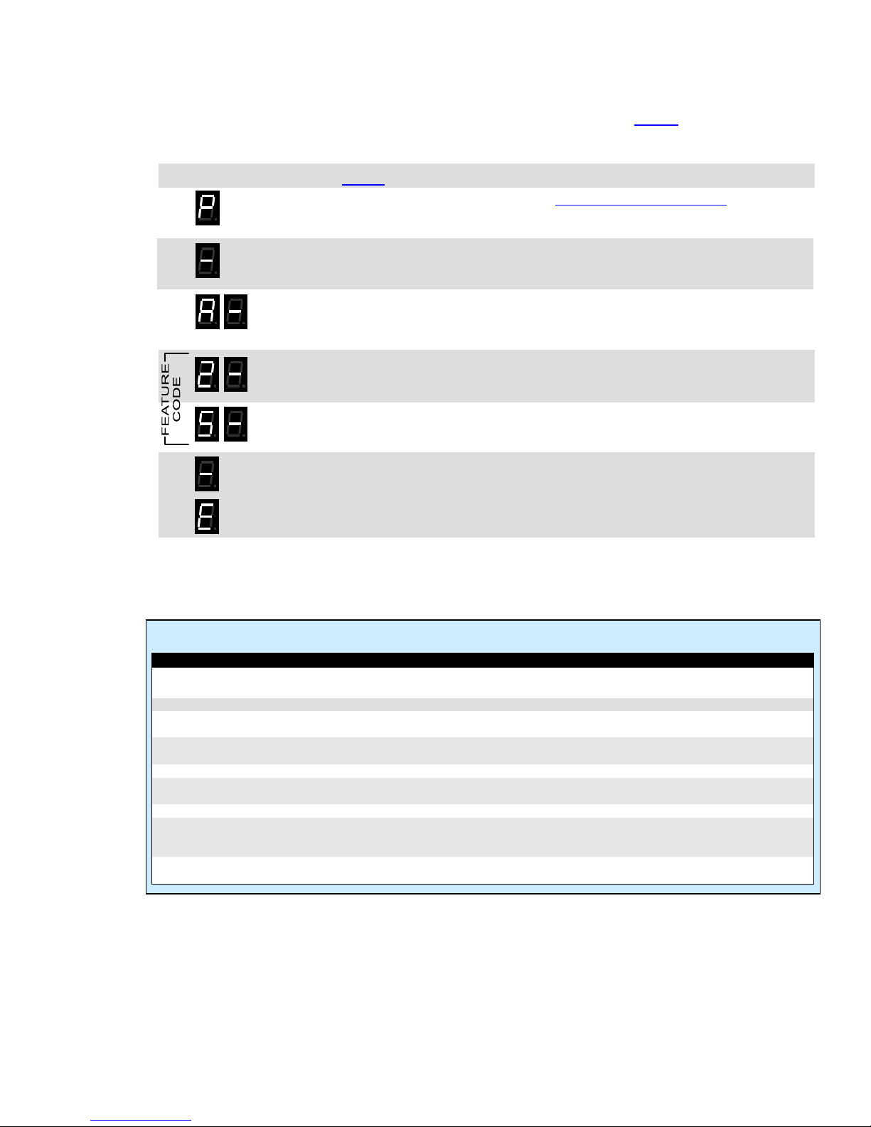
3.2 Readout Current Frequency, Tone and Selective Signaling Codes
1. Loosen the (4) captive screws in the front corners of the case. These screws are captive to the housing; to
prevent damaging them, DO NOT remove the screws from the housing.
. Separate the case front from the case back, leaving the RPS-1A power supply connected to the radio.
2
3. Press and release the PROGRAM button (See LPA-Series receiver assembly on page 2 for location). The
radio will immediately begin to display a series of digits; with each digit separated by a hyphen.
4. Write down the all the digits. The first two digits indicate the frequency code and the next two digits the tone
code; see Table 1 and Table 2 on page 16. In this example an LPA-U450 is programmed to operate on the
“Brown Dot” frequency of 464.500 MHz (Frequency code “04”) with 100.0 Hz tone (Tone code “12”).
FREQUENCY CODE TONE CODE
5. If a 5th digit is displayed, the LPA receiver has been programmed for DQC and the last three digits indicate the
DQC code; see Table 3 on page 16. In this example an LPA-U450 was programmed to operate on the
“Brown Dot” frequency of 464.500 MHz (Frequency code “04”) with a DQC code of “723”.
FREQUENCY CODE DQC CODE
6. If more than 5 digits are displayed, the radio has been programmed for Selective Signaling Decode. The
frequency and tone codes will be displayed, followed by a “C”, then the radio will display either the 2-digit, 2-
Tone paging code (see Table 4 on 16) or the 3-7 digit Selcall code. In this example an LPA-U450 was
programmed to operate on the “Brown Dot” frequency of 464.500 MHz (Frequency code “04”) with 100.0 Hz
tone (Tone code “12”) and 2-tone paging decode frequencies of 330.5 Hz and 569.1 Hz (2-Tone code “91”)
7. If the LPA-Series receiver is PC programmed with any frequency not listed in Table 1 on page 16, the radio
will display a code "99" for the frequency code. The PC programmer will be required to readout the radios
equency programming.fr
FREQUENCY CODE TONE CODE PAGING CODE
8. Normal radio operation resumes after the programming information has been displayed.
Section 3 Programming 12

3.3 Program Frequency & Tone Codes
To match other radios, the owner can select Frequency, Tone and DQC Codes from Table 1,Table 2 and Table 3.
In our example, we will program an LPA-U450 to operate on the "Brown Dot" frequency of 464.500 MHz with 100.0
Hz tone.
04
12
1. Refer to Table 1 to determine the two-digit frequency code and write it down.
2. Refer to Table 2 to determine the two-digit tone code for 100.0 Hz and write it down.
3. Loosen the (4) captive screws in the front corners of the case. These screws are captive to
the housing; to prevent damaging them, DO NOT remove the screws from the housing.
4. Separate the case front from the case back, leaving the RPS-1A power supply connected
to the radio.
5. Press and HOLD the PROGRAM button. A "P" will appear on the program display as you
enter program mode and the radio will beep rapidly.
6. Release the PROGRAM button after the beeping has stopped. The radio will emit a triple
beep indicating that the radio is in program mode and a hyphen will appear on the program
display.
7. Scroll to the character “F” by clicking the PROGRAM button until the program display
shows the correct character. Pause—the radio will sound a low tone and show a hyphen
across the center of the display to indicate that it is ready to accept the first digit of the
frequency code.
8. Enter the 1st digit of the frequency code by clicking the PROGRAM button until the
program display shows the desired number. Pause—the radio will sound a low tone and
show a hyphen across the center of the display to indicate that it is ready to accept the
next digit.
9. Enter the 2nd digit of the frequency code by clicking the PROGRAM button until the
program display shows the desired number. Pause—the radio sounds a low tone and will
show a hyphen across the center of the display to indicate that it is ready to accept the
next digit.
10. Enter the 1st digit of the tone code (or 1st digit of the DQC code) by clicking the PROGRAM
button until the program display shows the desired number. Pause—the radio sounds a
low tone and will show a hyphen across the center of the display to indicate that it is ready
to accept the next digit.
11. Enter the 2nd digit of the tone code (or 2nd digit of the DQC code) by clicking the
PROGRAM button until the program display shows the desired number. Pause—the radio
sounds a low tone and will show a hyphen across the center of the display to indicate that
it is ready to accept the next digit.
12. FOR DQC CODES ONLY – Enter the 3rd digit of the DQC code by clicking the PROGRAM
button until the program display shows the desired number. Pause—the radio sounds a
low tone and will show a hyphen across the center of the display to indicate that it is ready
to accept the next digit.
13. Press and release the ENTER button to save your programming. A triple beep will sound to
indicate that programming was successful and a hyphen will appear on the program
display. The radio is now ready for another program entry.
NOTE: An error tone will sound if you attempt to save an incorrect code, an "E" will appear
on the display. Check the digits you are attempting to enter, then re-enter.
14. Once you have made your final program entry, press the ENTER button a final time to exit
programming mode. The Program display will be blank and the radio will be ready for use.
The LPA-Series receiver will exit program mode automatically after 30 seconds if no
program entries are attempted.
Section 3 Programming 13

Section 3 Programming 14
Table 2: Interference Eliminator Programmable QC Tone Codes
Table 3: Digital Interference Eliminator Programmable DQC Tone Codes
Table 1: Programmable Frequency Codes
VHF Business Band
Code Frequency Color Dot BW
03 151.625 Red Dot 25
04 151.955 Purple Dot 25
05 151.925 25
06 154.540 25
07 154.515 25
08 154.655 25
10 151.715 25
09 151.685 25
11 151.775 25
12 151.805 25
13 151.835 25
14 151.895 25
15 154.490 25
16 151.655 25
17 151.745 25
18 151.865 25
24 151.700 12.5
25 151.760 12.5
26 152.700 25
99 Custom programmed ---
VHF MURS**
01 154.600 Green Dot 25
02 154.570 Blue Dot 25
19 151.820 MURS 12.5
20 151.880 MURS 12.5
21 151.940 MURS 12.5
22 154.600 MURS 12.5
23 154.570 MURS 12.5
UHF Business Band
Code Frequency Color Dot BW
01 467.7625 J 25
02 467.8125 K 25
03 464.5500 Yellow Dot 25
04 464.5000 Brown Dot 25
05 467.8500 Silver Star 25
06 467.8750 Gold Star 25
07 467.9000 Red Star 25
08 467.9250 Blue Star 25
09 469.2625 25
10 462.5750 White Dot 25
11 462.6250 Black Dot 25
12 462.6750 Orange Dot 25
13 464.3250 25
14 464.8250 25
15 469.5000 25
16 469.5500 25
17 463.2625 25
18 464.9125 25
19 464.6000 25
20 464.7000 25
21 462.7250 25
22 464.5000 12.5
23 464.5500 12.5
24 467.7625 12.5
25 467.8125 12.5
26 467.8500 12.5
27 467.8750 12.5
28 467.9000 12.5
29 467.9250 12.5
30 461.0375 12.5
31 461.0625 12.5
UHF Business Band
Code Frequency Color Dot BW
32 461.0875 12.5
33 461.1125 12.5
34 461.1375 12.5
35 461.1625 12.5
36 461.1875 12.5
37 461.2125 12.5
38 461.2375 12.5
39 461.2625 12.5
40 461.2875 12.5
41 461.3125 12.5
42 461.3375 12.5
43 461.3625 12.5
44 462.7625 12.5
45 462.7875 12.5
46 462.8125 12.5
47 462.8375 12.5
48 462.8625 12.5
49 462.8875 12.5
50 462.9125 12.5
51 464.4875 12.5
52 464.5125 12.5
53 464.5375 12.5
54 464.5625 12.5
55 466.0375 12.5
56 466.0625 12.5
57 466.0875 12.5
58 466.1125 12.5
59 466.1375 12.5
60 466.1625 12.5
61 466.1875 12.5
62 466.2125 12.5
UHF Business Band
Code Frequency Color Dot BW
63 466.2375 12.5
64 466.2625 12.5
65 466.2875 12.5
66 466.3125 12.5
67 466.3375 12.5
68 466.3625 12.5
69 467.7875 12.5
70 467.8375 12.5
71 467.8625 12.5
72 467.8875 12.5
73 467.9125 12.5
74 469.4875 12.5
75 469.5125 12.5
76 469.5375 12.5
77 469.5625 12.5
99 Custom programmed ----
Canadian Models
UHF Canada
01 458.6625 25
02 469.2625 25
VHF Canada
01 151.055 25
02 151.115 25
British Columbia
01 154.100 25
02 158.940 25
Notes: ** MURS frequencies do not require an FCC license. All other frequencies require an FCC license.
•BW is the bandwidth in kHz. 12.5 kHz = narrow band channel, 25 kHz = wide band channel.
Code Frequency
01 67.0
02 71.9
03 74.4
04 77.0
05 79.7
06 82.5
07 85.4
08 88.5
09 91.5
Code Frequency
10 94.8
11 97.4
12 100.0
13 103.5
14 107.2
15 110.9
16 114.8
17 118.8
18 123.0
Code Frequency
19 127.3
20 131.8
21 136.5
22 141.3
23 146.2
24 151.4
25 156.7
26 162.2
27 167.9
Code Frequency
28 173.8
29 179.9
30 186.2
31 192.8
32 203.5
33 210.7
34 218.1
35 225.7
36 233.6
Code Frequency
37 241.8
38 250.3
39 69.4
40 159.8
41 165.5
42 171.3
43 177.3
44 No Tone
45 183.5
Code Frequency
46 189.9
47 196.6
48 199.5
49 206.5
50 229.1
51 254.1
00 No Tone
Code
023
025
026
031
032
036
043
047
051
053
054
Code
065
071
072
073
074
114
115
116
122
125
131
Code
132
134
143
145
152
155
156
162
165
172
174
Code
205
212
223
225
226
243
244
245
246
251
252
Code
255
261
263
265
266
271
274
306
311
315
325
Code
331
332
343
346
351
356
364
365
371
411
412
Code
413
423
431
432
445
446
452
454
455
462
464
Code
465
466
503
506
516
523
532
546
565
606
662
Code
612
624
627
631
632
645
654
664
703
712
723
Code
731
732
734
743
754

3.4 Program Paging Codes
For paging, it is desirable to program the LPA-Series receiver for 2-Tone or Selcall operation. The user is able to
field program the radio for one of the 9 pre-determined 2-tone pairs specified in Table 4, or for a 3-7 digit Selcall
code. 2-Tone codes correspond to field programmable 2-Tone encode (transmit) codes available in other RITRON
portable and base radios. In our example we will program an LM-U450 to operate with 2-Tone Paging Code 94
frequencies of 389.0 and 669.9 Hz.
94 1. Refer to Table 4 to determine the two-digit code for 2-tone decode on 389.0 and 669.9 Hz
and write it down.
2. Loosen the (4) captive screws in the front corners of the case. These screws are captive to
the housing; to prevent damaging them, DO NOT remove the screws from the housing.
3. Separate the case front from the case back, leaving the RPS-1A power supply connected
to the radio.
4. Press and HOLD the PROGRAM button. A "P" will appear on the program display as you
enter program mode and the radio will beep rapidly.
5. Release the PROGRAM button after the beeping has stopped. The radio will emit a triple
beep indicating that the radio is in program mode and a hyphen will appear on the program
display.
6. Scroll to the character “C” by clicking the PROGRAM button until the program display
shows the correct character. Pause—the radio will sound a low tone and show a hyphen
across the center of the display to indicate that it is ready to accept the first digit of the 2-
Tone or Selcall code.
7. Enter the 1st digit of the 2-Tone or Selcall code by clicking the PROGRAM button until the
program display shows the desired number. Pause—the radio will sound a low tone and
show a hyphen across the center of the display to indicate that it is ready to accept the
next digit.
8. Enter the 2nd digit of the 2-Tone or Selcall code by clicking the PROGRAM button until the
program display shows the desired number. Pause—the radio sounds a low tone and
show a hyphen across the center of the display to indicate that it is ready to accept the
next digit.
9. FOR SELCALL CODES ONLY – Enter the 3rd, 4th, 5th, 6th, and 7th digits of the Selcall code
by clicking the PROGRAM button until the program display shows the desired number.
Pause—the radio sounds a low tone and will show a hyphen across the center of the
display to indicate that it is ready to accept the next digit.
10. Press and release the ENTER button to save your programming. A triple beep will sound to
indicate that programming was successful and a hyphen will appear on the program
display. The radio is now ready for another program entry.
NOTE: An error tone will sound if you attempt to save an incorrect code, an "E" will appear
on the display. Check the digits you are attempting to enter, then re-enter.
11. Once you have made your final program entry, press the ENTER button a final time to exit
programming mode. The Program display will be blank and the radio will be ready for use.
The LPA-Series receiver will exit program mode automatically after 30 seconds if no
program entries are attempted.
Section 3 Programming 15
Table 4: 2-Tone Paging Codes
Code Tone 1 Tone 2
90 * *
91 330.5 569.1
92 349.0 600.9
93 368.5 634.5
94 389.0 669.9
95 410.8 707.3
96 433.7 746.8
97 457.9 788.5
98 483.5 832.5
99 330.5 600.9
00 No Selective Signaling
IMPORTANT NOTE:
* If the LPA-Series receiver displays 2-Tone Paging Code “90”
on readout, it has been PC programmed for custom 2-Tone
frequencies. Entering code “90” will cause the LPA-Series
receiver to operate on the PC programmed custom 2-Tone
frequencies.
3.5 Program LPA-Series Features
The LPA-Series receiver can be field programmed for a variety of features. Refer to Table 5 for the two digit codes
available for field programming. In our example we will program an LPA-U450 for Record and Play operation. The
LPA-Series receiver is set from the factory with these √options enabled.
13 1. Refer to Table 5 to determine the two-digit feature code and write it down.
2. Press and HOLD the PROGRAM button (See LPA-Series receiver assembly on page 2 for
location). A "P" will appear on the program display as you enter program mode and the
radio will beep rapidly.
3. Release the PROGRAM button after the beeping has stopped. The radio will emit a triple
beep indicating that the radio is in program mode and a hyphen will appear on the program
display.
4. Scroll to the character “A” by clicking the PROGRAM button until the program display
shows the correct character. Pause—the radio will sound a low tone and show a hyphen
across the center of the display to indicate that it is ready to accept the first digit of the
Feature code.
5. Enter the 1st digit of the feature code by clicking the PROGRAM button until the program
display shows the desired number. Pause—the radio will sound a low tone and show a
hyphen across the center of the display to indicate that it is ready to accept the next digit.
6. Enter the 2nd digit of the feature code by clicking the PROGRAM button until the program
display shows the desired number. Pause—the radio sounds a low tone and will show a
hyphen across the center of the display to indicate that it is ready to accept the next digit.
7. Press and release the ENTER button to save your programming. A triple beep will sound to
indicate that programming was successful and a hyphen will appear on the program
display. The radio is now ready for another program entry.
NOTE: An error tone will sound if you attempt to save an incorrect code, an "E" will appear
on the display. Check the digits you are attempting to enter, then re-enter.
8. Once you have made your final program entry, press the ENTER button a final time to exit
programming mode. The Program display will be blank and the radio will be ready for use.
The LPA-Series receiver will exit program mode automatically after 30 seconds if no
program entries are attempted.
Table 5: Feature Codes
Code Feature Default Description
Special Features
21 Reset to Factory Defaults Resets Wireless Speaker to Factory default programming.
22 Display Radio Revision LPA receiver will display a sequence of 6 digits to identify operating code
revision. This is helpful when troubleshooting the radio.
23 Pre-Announce Tone – On √Enable this feature to play a short tone over the PA system speakers
whenever the LPA receiver receives a signal.
24 Pre-Announce Tone – Off Disable Pre-Announce Tone
25 Record and Play – On When set received messages are recorded and played back over the PA
system speakers immediately after the received signal is removed.
26 Record and Play – Off √Disable Record and Play feature
29 Weather Alert – On Enable this feature to receive local NOAA weather radio emergerncy
broadcasts from the National Weather Service and play them over the PA
system speaker. This feature is only available on the LPA-V150.
20 Weather Alert – Off √Disable Weather Alert
Section 3 Programming 16

3.6 Program LPA-Series Volume
The LPA-Series receiver can be field programmed for any volume level between 05-99% by entering the volume
level as a 2-digit code. The LPA receiver is set from the factory with a 50% volume setting. If your PA amplifier
has independant volume control you should not have to adjust the LPA receiver volume. If there is no volume
control, or if the PA amplifier volume control is pre-set for background music, you can adjust the input level to the
PA amplifier by adjusting the LPA receiver volume. Field programming Volume Level sets both the voice and the
pre-announce tone volume levels. The PC programmer is required for independent programming of the voice and
the pre-announce tone volume.
In our example we will program an LPA-U450 for 25% Speaker Volume Level.
1. Press and HOLD the PROGRAM button (See LPA-Series receiver assembly on page 2 for
location). A "P" will appear on the program display as you enter program mode and the
radio will beep rapidly.
2. Release the PROGRAM button after the beeping has stopped. The radio will emit a triple
beep indicating that the radio is in program mode and a hyphen will appear on the program
display.
3. Scroll to the character “U” by clicking the PROGRAM button until the program display
shows the correct character. Pause—the radio will sound a low tone and show a hyphen
across the center of the display to indicate that it is ready to accept the first digit of the
volume setting.
4. Enter the 1st digit of the volume setting by clicking the PROGRAM button until the program
display shows the desired number. Pause—the radio will sound a low tone and show a
hyphen across the center of the display to indicate that it is ready to accept the next digit.
5. Enter the 2nd digit of the volume setting by clicking the PROGRAM button until the program
display shows the desired number. Pause—the radio sounds a low tone and will show a
hyphen across the center of the display to indicate that it is ready to accept the next digit.
6. Press and release the ENTER button to save your programming. A triple beep will sound to
indicate that programming was successful and a hyphen will appear on the program
display. The radio is now ready for another program entry.
NOTE: An error tone will sound if you attempt to save an incorrect code, an "E" will appear
on the display. Check the digits you are attempting to enter, then re-enter.
7. Once you have made your final program entry, press the ENTER button a final time to exit
programming mode. The Program display will be blank and the radio will be ready for use.
The LPA-Series receiver will exit program mode automatically after 30 seconds if no
program entries are attempted.
IMPORTANT NOTE: Volume settings below 10% are entered as a 2-digit code with a first digit “0”.
Checking the Current Volume Setting
To readout the current volume setting, follow the instructions above and enter a
volume setting code “00”. When you press the ENTER button the radio will
immediately begin to display the 2-digit volume setting; with each digit separated by
a hyphen.
Section 3 Programming 17
This manual suits for next models
1
Table of contents
Other Ritron Speakers manuals


