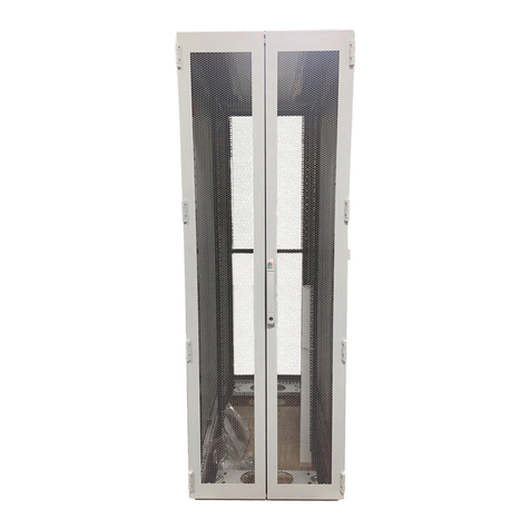
Rittal Micro Data Center Level E User manual

Micro Data Center Level E
7999.009
Operating instructions

Foreword
EN
2Rittal Micro Data Center Level E
Foreword
Dear Customer!
We thank you for choosing our Micro Data Center
Level E.
We wish you every success!
Your,
Rittal GmbH & Co. KG
Rittal GmbH & Co. KG
Auf dem Stützelberg
35745 Herborn
Germany
Tel.: +49(0)2772 505-0
Fax: +49(0)2772 505-2319
E-mail: info@rittal.de
www.rittal.com
www.rittal.de
We are always happy to answer any technical
questions regarding our entire range of products.

Rittal Micro Data Center Level E 3
Contents
EN
Contents
1 Notes on documentation .................. 4
1.1 Manufacturer's statement ............................. 4
1.2 Storing the documents .................................. 4
1.3 Symbols in these operating instructions ........ 4
1.4 Other applicable documents ......................... 4
2 Safety instructions ............................ 5
2.1 Safety notes for personnel protection ............ 5
2.2 Safety notes for the prevention of damage
to the Micro Data Center ...............................6
2.3 Operating and technical staff ......................... 7
2.4 RoHS compliance ......................................... 7
3 Product Description ......................... 8
3.1 Functional description ................................... 8
3.2 Components of the Micro Data Center .......... 8
3.3 Standard system components ...................... 9
3.3.1 Cable duct ............................................................ 9
3.4 Proper use, foreseeable misuse .................... 9
3.5 Dimensions and clearances ........................ 10
3.6 Scope of supply .......................................... 10
4 Assembly and siting ....................... 11
4.1 Installation site requirements ....................... 11
4.1.1 Average surface load of the Micro Data Center
Level E ............................................................... 13
5 Transport ....................................... 15
6 Installation and commissioning ....... 16
7 Operation ....................................... 17
7.1 Handling the doors ..................................... 17
7.1.1 Mechanical key lock ........................................... 17
7.1.2 Code-Combi B electronic key combination lock . 18
7.1.3 Electronic lock for activation by an access control
system ............................................................... 25
8 Inspection and maintenance .......... 27
8.1 Safety instructions ....................................... 27
8.2 Maintenance of the safety cell ..................... 27
8.3 Maintenance contract ................................. 27
9 Storage and disposal ..................... 28
9.1 Storage ....................................................... 28
9.2 Disposal ...................................................... 28
10 Technical specifications ................. 29
11 Accessories ................................... 30
11.1 TS-IT server enclosure accessories ............. 31
12 Appendixes .................................... 34
12.1 Cooling the Micro Data Center .................... 34
13 Warranty ........................................ 35
14 Customer service addresses .......... 36

1 Notes on documentation
EN
4Rittal Micro Data Center Level E
1 Notes on documentation
1.1 Manufacturer's statement
Rittal GmbH & Co. KG confirms that the applicable safe-
ty standards for the Micro Data Center Level E are ob-
served.
1.2 Storing the documents
The operating instructions as well as all applicable doc-
uments are integral components of the product. They
must be handed out to those persons who are engaged
with the unit and must always be available and on hand
for operating and maintenance personnel.
1.3 Symbols in these operating instructions
The following symbols are used in this documentation:
This symbol indicates an "Action Point" and shows
that you should perform an operation/procedure.
1.4 Other applicable documents
– Manufacturer's statement
– Operating instructions of all components sold and in-
stalled by Rittal
Danger!
This warning symbol is used to indicate
great dangers caused by the product
which may result in injury and even
death if the preventative measures indi-
cated are not followed.
Warning!
This warning symbol is used to indicate
procedures which may cause risk of
equipment damage or personal injury.
Note:
This instruction symbol indicates information
concerning individual procedures, explana-
tions, or tips for simplified approaches.

Rittal Micro Data Center Level E 5
2 Safety instructions
EN
2 Safety instructions
The Micro Data Center Level E produced by Rittal
GmbH & Co. KG is developed and produced with due
regard to all safety precautions. Nevertheless, the unit
still causes a number of unavoidable dangers and risks.
The safety instructions provide you with an overview of
these dangers and the necessary safety precautions.
In the interests of your safety and the safety of others,
please read these safety instructions carefully before as-
sembly and commissioning of the Micro Data Center
Level E.
Follow the user information found in these instructions
and on the unit carefully.
2.1 Safety notes for personnel protection
Danger! Electric shock!
Work performed unprofessionally on the
electrical equipment of the Micro Data
Center can cause serious injuries and
death.
Work on the electrical equipment of the
Micro Data Center may be performed
only by an electrician or by trained per-
sonnel guided and supervised by an
electrician. All work must be performed
in accordance with electrical engineer-
ing regulations.
The mains connection data cited on the
rating plate must be adhered to.
Prior to performing any maintenance
work, the Micro Data Center must be
disconnected from the mains power.
Danger! Electric shock!
Contact to live parts can cause severe
injuries or death.
Ensure that the customer-supplied po-
tential equalisation has been performed
professionally and connected with the
central earthing point in the Micro Data
Center.
Also ensure the reliable protective earth-
ing of all built-in components.
Ensure the adequately dimensioned cur-
rent carrying capacity of the potential
equalisation.
The customer must earth the built-in
components.
Explosion hazard
If UPSs with integrated or separate bat-
tery packs are installed in the Micro Data
Center, this can lead to an explosion.
UPSs with integrated batteries or sepa-
rate battery packs may be installed in
the Micro Data Center only with ade-
quate ventilation in accordance with
EN 50272-2.
Danger of collapse
The failure of the building structure can
cause severe injuries and death.
Prior to the assembly of the Micro Data
Center, check the requirements placed
on the building statics.
The Micro Data Center may be posi-
tioned only where the building structure
is dimensioned adequately.
Danger of becoming trapped
Injuries can occur when the safety doors
are opened or closed.
Ensure that you do not reach between
the door and frame while opening and
closing the doors. Maintain an adequate
safety clearance.
Blocked escape routes
In case of an emergency, blocked es-
cape routes can lead to injuries or death.
Ensure for the choice of the Micro Data
Center installation location that ade-
quately-wide escape routes are present.
Do not place any objects in the area of
the Micro Data Center's safety doors.
Confinement of persons
The confinement of persons in the not-
fully equipped Micro Data Center can
lead to injuries.
Before closing the not-fully equipped
Micro Data Center, ensure that no per-
sons are still present in the Micro Data
Center.

2 Safety instructions
EN
6Rittal Micro Data Center Level E
Also observe the following safety notes:
– Any mains power connection or mains power wiring
required as part of the Micro Data Center Level E wir-
ing may only be performed by an experienced electri-
cian.
– Do not modify the unit!
– Use only original spare parts!
– The Micro Data Center does not provide any protec-
tion against standing or rising water.
– During normal operation, the Micro Data Center must
not come in contact with water, aggressive or inflam-
mable gases and vapours.
– The Micro Data Center may only be operated within
the specified environmental conditions (see section 10
"Technical specifications").
– Observe any national regulations for accident preven-
tion.
– Observe any company-internal regulations.
– Observe all special safety notes associated with the in-
dividual tasks in the appropriate sections.
2.2 Safety notes for the prevention of dam-
age to the Micro Data Center
Caution!
There is the danger of tipping when the
doors are opened 180° and the housing
is empty!
If necessary, secure the Micro Data
Center to a solid surface.
Caution!
There is the danger of tipping when
more than one component is pulled-out
from the 482.6 mm (19") level.
Pull-out only one component from the
482.6 mm (19") level at a time.
Caution!
There is danger caused by falling devic-
es. No devices may be installed on the
internal mounting rails when they are ad-
justed. The failure to adhere to this rule
can lead to severe injuries and/or dam-
age to devices.
Note:
The Micro Data Center may only be installed
vertically on a flat floor with max. 2° deviation
to guarantee the correct function of the safe-
ty doors.
Note:
Do not change the location of the Micro Data
Center yourself and do not disassemble it
yourself.
Contact the manufacturer or a service com-
pany authorised by the manufacturer to per-
form this work.
Note:
Prior to the assembly of the Micro Data
Center, check the requirements placed on
the operational environment.
The Micro Data Center may be used only for
the approved indoor application.
With this regard, also observe the manufac-
turer's details for the components to be in-
stalled. In particular, the permitted environ-
mental parameters, such as temperature, air
humidity and the requirements placed on the
ambient air, must be observed.
Do not obstruct or adjust the air inlets and
outlets of the cooling system on the inside
and the outside of the Micro Data Center.
The heat load inside the Micro Data Center
must not exceed the rated power specified
on the rating plate of the cooling system.
The ambient temperature at the installation
site of the Micro Data Center must lie within
the temperature limits of +10 °C and +35 °C.
Ensure adequate ventilation or climate con-
trol of the installation site.
Note:
Use only original spare parts. Should spare
parts be required, contact customer service
at Rittal.
Note:
Store the keys for opening the safety doors
only at a location that cannot be accessed by
unauthorised persons. Never save the keys in
the Micro Data Center.
Note:
After completion of the cooling unit installa-
tion, wait at least two hours before placing
the unit into operation. The commissioning
must be performed by authorised personnel.
The customer is responsible for the correct
operation of the condensate discharge rout-
ed through the cable duct.

Rittal Micro Data Center Level E 7
2 Safety instructions
EN
2.3 Operating and technical staff
– The mounting, installation, commissioning, mainte-
nance and repair of this unit may be performed only by
qualified mechanical and electro-technical trained per-
sonnel.
– Only properly instructed personnel may work on a unit
while in operation.
2.4 RoHS compliance
The unit fulfills the requirements of EU directive
2011/65/EU on the Restriction of Use of Certain Hazard-
ous Substances in Electrical and Electronic Equipment
(RoHS 2) of June 08, 2011.
Note:
The safety doors of the Micro Data Center
can be opened only to a limited extent. Do
not attempt to force the doors open further
because this would damage the Micro Data
Center.
Note:
Before you close the doors, the safety bolts
must be retracted. Otherwise the Micro Data
Center will be damaged.
Note:
Never drill any holes in the side panels, top or
floor elements or the safety doors without
consulting the manufacturer. This can cause
damage to the insulation materials of the Mi-
cro Data Center walls.
Any warranty claim is void in this case!
Note:
After the commissioning of the Micro Data
Center, do not have any keys duplicated by a
key service. If you require additional keys,
please contact the Rittal service department.
If keys get lost, the lock must be replaced
without delay.
Note:
After incursions, attempted incursions, im-
proper intrusions in the design and function
as well as cases of water ingress and fires
within and in the immediate vicinity of the Mi-
cro Data Center, the validity of the recogni-
tion of the test ratings is voided. In such
cases, please contact Rittal without delay
otherwise the warranty is voided.
Note:
Corresponding information about the RoHS
Directive may be found on our website at
www.rittal.com/RoHS.

3 Product Description
EN
8Rittal Micro Data Center Level E
3 Product Description
3.1 Functional description
The Rittal Micro Data Center Level E is a modularly ex-
tendible IT security safe. It provides physical safety and
protects against fire, water, acrid gases and unauthor-
ised access.
Components that characterise a data centre can be in-
tegrated in various variants. Starting with energy-
efficient climate control matched to the requirements, in-
cluding energy distribution, through to early fire protec-
tion and extinguisher systems.
The Micro Data Center provides physical protection
against:
1) The Micro Data Center was tested as a system.
2) The Single Micro Data Center was tested as a system
with single-leaf doors and a mechanical lock.
3) The Single Micro Data Center was tested as a system
with a single-leaf door and a double-leaf door, each with
a mechanical lock.
3.2 Components of the Micro Data Center
Fig. 1: Components of the Micro Data Center
1 Top element
2 Service door
3 Operator door
4 Side elements
5 Floor element
The Rittal Micro Data Center Level E consists of individ-
ual elements that are combined with a positive-
engagement connection system. The special connec-
tion system permits a subsequent dismantling and so
also an expansion of the system or its installation at a dif-
ferent location.
High-temperature, expansion and water-resistant seals
are provided between the joints of the cell elements.
The elements consist of a multi-layer insulant structure
mounted in a sheet steel cassette.
In its standard variant, the modular safety cell consists of
a top and a floor element, two side elements, operator
and service door as well as two mounting frames. As
standard, different locks are installed in both doors. The
two side elements are equipped with a cable duct.
The Micro Data Center is equipped with a potential
equalisation rail that the customer must earth to a central
earthing point.
The customer must connect the frame correctly with the
potential equalisation rail.
The split unit used for the cooling prevents dust and cor-
rosive combustion gases from entering the Micro Data
Center. Several variants and power ranges adapted to
Fire: Fire resistance F 90 in accordance with
DIN 4102 as well as the observance of the
maximum temperature increase of 50 K and
a relative humidity of maximum 85% for
30 minutes1)
Extinguishing-water resistance in accord-
ance with IEC 60529 IP X63)
Smoke protection based on DIN 180953)
Intrusion protection RC 2, optionally RC 3,
tool attack similar to DIN EN 16303),
optionally selectable RC 4, tool attack similar
to DIN EN 16302)
Dust-proofing in accordance with IEC 60529
IP 5X3)
Unauthorised access
Smoke protection based on
DIN 18 095-2: 1991-033)

Rittal Micro Data Center Level E 9
3 Product Description
EN
the heat load and the customer conditions can be cho-
sen.
The CMC can optionally be used as network-compatible
monitoring system for monitoring the interior.
An early fire detection as well as fire alarm and extin-
guishing system can also be integrated as 482.6 mm
(19") components and offer a high degree of safety.
Various busbars adapted to the power distribution re-
quirements are available.
3.3 Standard system components
3.3.1 Cable duct
Soft duct
The soft duct consists of flexible material that can be in-
stalled around the data and supply lines to be intro-
duced into the Micro Data Center. The cables to be in-
troduced must be distributed separately to the individual
positions. To ensure the guaranteed characteristics
against external danger potentials, no bundled cables
may be introduced into the Micro Data Center.
After introduction of all cables, the complete area of the
cable duct is sealed externally and internally.
The soft duct has the dimension W x H 165 x 267 mm
and may be occupied with cables to the maximum level
of 60%.
The following cables and supply lines may be inserted
through the duct:
– Steel tubes to max. 18 mm diameter
– Cables to max. 15 mm diameter
When steel tubes are inserted, an additional cable duct
protection box must be placed in front of the soft duct.
Cable box
The cable box for the introduction of data and supply ca-
bles consists of a sheet steel enclosure lined on all sides
with alkaline-silicate blocks. In case of fire or tempera-
tures above 100 °C, this material swells and closes the
cable opening.
On the face side, the cable box is closed smoke-tight.
After the introduction of all cables and supply lines, the
cable entrance must be sprayed to become smoke
tight.
The cable box is divided into two areas:
– Dimension area 1: 26 x 214 mm
– Dimension area 2: 44 x 214 mm
To permit the passage of larger connector plugs, the
centre bar can be removed but must be replaced before
being sealed.
The cable box can be occupied 100%.
The cable box may be occupied with cables with maxi-
mum 15 mm diameter. The cable box may be occupied
with 3311.040 water supply and return hoses for the
LCP. No steel tubes may be fed through the cable box.
Hard duct
To guarantee large manipulation assurance in the cable
duct area, a hard duct can be deployed optionally. Each
cable is laid with a filler piece matched to the cable di-
ameter. An end seal ensures the pressing-in of the com-
plete system.
For stabilisation, the duct system is inserted in a con-
struction frame that absorbs the pressure.
The following cables and supply lines may be inserted
through the duct:
– Cables to max. 15 mm diameter
3.4 Proper use, foreseeable misuse
The unit may be used only for the acceptance of IT com-
ponents while also providing protection against dan-
gers, such as fire, water or unauthorised access. Any
other use is not permitted.
The unit is state of the art and built according to recog-
nised safety regulations. Nevertheless, improper use
can present a hazard to life and limb of the user or third
parties, or result in possible damage to the system and
other property.
Consequently, the unit must only be used properly and
in a technically sound condition! Any malfunctions which
impair safety should be rectified immediately! Observe
the operating instructions!
The intended use also includes the observance of the
provided documentation and fulfilling the inspection and
maintenance conditions.
Rittal GmbH & Co. KG is not responsible for any damage
which may result from failure to comply with the docu-
mentation provided. The same applies to failure to com-
ply with the valid documentation for accessories used.
Note:
The connection of the cable ducts and also
expansions in a previously closed cable duct
may only be performed by authorised service
personnel otherwise the warranty will be
voided! If further lines or cables should be in-
serted in a cable duct, the manufacturer must
be informed.

3 Product Description
EN
10 Rittal Micro Data Center Level E
Inappropriate use may result in danger. Inappropriate
use includes:
– Use of impermissible tools.
– Improper operation.
– Improper rectification of malfunctions.
– Use of accessories not approved by Rittal GmbH &
Co. KG.
3.5 Dimensions and clearances
Information about the dimensions can be found on the
dimensioned drawings in the Appendix.
Clearances to be observed for the erection of the
Micro Data Center are listed in section 4.1 "Installation
site requirements".
3.6 Scope of supply
– Micro Data Center Level E
– Accessories provided (in accordance with the order
confirmation)
– Operating instructions

Rittal Micro Data Center Level E 11
4 Assembly and siting
EN
4 Assembly and siting
4.1 Installation site requirements
Customer requirements:
The items listed below are the standard requirements
placed on the siting of the Micro Data Center Level E and
must be satisfied by the customer.
1. Transport path
An adequately dimensioned transport path for com-
ponents as large as 1300 x 2400 mm as well as ad-
equate storage and mounting area in the immediate
vicinity of the installation site area.
2. Fire-resistance class of the installation site surface
Fire-resistance class of the floor F 90 in accordance
with DIN 4102 for carrying or solid components.
3. Floor flatness
The installation site of the safety safe must be con-
structed level in accordance with DIN 18203
(smooth surface).
4. Room height
The clear height at the installation site of the Micro
Data Center must be at least 15 cm higher than the
height of the Micro Data Center. If the Micro Data
Center is equipped with cable entry in the top ele-
ment, appropriate additional space must be provid-
ed for the bending radiuses of the cables to be intro-
duced.
5. Traffic area / escape and rescue routes
The traffic area at the installation site of the Micro
Data Center must be adequately dimensioned not
only for the service and maintenance work and for
connecting the required cables. Accessibility from all
sides must be ensured. The escape and rescue
routes must remain free.
6. Room ventilation / climate control of the installation
site
The temperature at the installation site of the Micro
Data Center must lie in the range +10 °C to +35 °C.
If the external unit of the air-conditioner is mounted
directly on the Micro Data Center, the installation site
must be ventilated or air-conditioned appropriately.
7. Power supply / guaranteed climate control
– 3311.490 Liquid Cooling Unit LCU DX 3 kW:
operational voltage 230 V, 1 Ph/50 Hz/N/PE; line-
side time delay fuse 16 A
– 3311.491 Liquid Cooling Unit LCU DX 3 kW redun-
dant:
operational voltage 2 x 230 V, 1 Ph/50 Hz/N/PE;
line-side time delay fuse 16 A 2 x
– 3311.492 Liquid Cooling Unit LCU DX 6,5 kW:
operational voltage 230 V, 1 Ph/50 Hz/N/PE; line-
side time delay fuse 20 A
– 3311.493 Liquid Cooling Unit LCU DX 6,5 kW re-
dundant:
operational voltage 2 x 230 V, 1 Ph/50 Hz/N/PE;
line-side time delay fuse 20 A 2 x
– Power for the LCU DX must be supplied at the ex-
ternal unit.
8. Cut-outs
The customer is responsible for creating and closing
of the drilled tapped holes and cut-outs as well as
the opening and closing of the existing intermediate
floors and floors.
9. The customer must ensure that the protective con-
ductor is fed from outside and connected correctly
with the potential equalisation rail in the Micro Data
Center. This connection must be labelled (symbol
60417-ICE-5019). Always ensure that the protective
conductor has an adequate current-carrying capac-
ity.
10. Built-in components
Note that the selected built-in components (e.g.
CMC III monitoring system, DET-AC III fire alarm and
extinguishing system, etc.) require height units in the
482.6 mm (19") level.
The fire alarm and extinguishing system must be in-
stalled at the top in the 482.6 mm (19") level.
11. Requirements placed on the customer building
weight loadings
The floor at the installation site of the Micro Data
Center must be adequately dimensioned to accept
the static load of the Micro Data Center, including all
components.
The Micro Data Center must be installed on a level and
load-bearing bare reinforced-concrete floor in accord-
ance with Eurocode 2 [1] as well as the associated Ger-
man national Appendix [2] for Eurocode 2. The floor
must be able to carry the uniformly distributed charac-
teristic live load of q k5.0 kN/m² (corresponds to
500 kg/m²) in the area of the Micro Data Center instal-
lation area at least with a two-axis construction.
If the floor construction does not conform to the speci-
fied European regulations or the Micro Data Center is in-
itially positioned on a floor covering or a floating floor, a
static calculation must be made prior to installation of
the Micro Data Center to check whether the floor-cover-
ing construction can handle the special loading for the
overall Micro Data Center load, also when it is fully
equipped.
If the floor construction conforms to the specified Euro-
pean regulations for a bare reinforced-concrete floor and
a uniformly distributed live load of
qk5.0 kN/m² is involved, the Micro Data Center may
also be installed without static calculation in the following
rooms in accordance with Eurocode 1 [3].
The bare floor loadings of q k5.0 kN/m² in accordance
with [3] Table 6.1 DE
category B, line 6
category C, lines 9 to 12,
category D, lines 14 to 15, and
category E, lines 16 to 18 must be able to be applied.

4 Assembly and siting
EN
12 Rittal Micro Data Center Level E
In particular, in accordance with [3], the following utilisa-
tion categories for floors with vertical live loads are listed:
Category B3, line 6:
office areas, work areas and corridors and kitchens in
hospitals, hotels, retirement homes, corridors in board-
ing schools, treatment rooms in hospitals, including op-
erating rooms, with loading caused by heavy devices
with adequate lateral distribution in accordance with [2]
and with permitted uniformly distributed characteristic
live loads of q k5.0 kN/m².
Category C3, line 9:
meeting rooms and areas used for groups of persons,
including museum areas, exhibition areas, reception ar-
eas in public buildings, hotels, cellar ceilings not suitable
for traffic, with adequate lateral distribution in accord-
ance with [2] and permitted uniformly distributed char-
acteristic live loads of q k5.0 kN/m².
Category C4, line 10:
sport and playing areas, such as dance halls, sport halls,
theatre stages, with adequate lateral distribution in ac-
cordance with [2] and permitted uniformly distributed
characteristic live loads of q k5.0 kN/m².
Category C5, line 11:
areas for large groups of people, such as concert halls,
terraces and entrance areas as well as grandstands with
fixed seating, with adequate lateral distribution in ac-
cordance with [2] and permitted uniformly distributed
characteristic live loads of q k5.0 kN/m².
Category C6, line 12:
areas for regular use by large groups of persons, grand-
stands without fixed seating, with adequate lateral distri-
bution in accordance with [2] and permitted uniformly
distributed characteristic live loads of q k7.5 kN/m².
Category D2, line 14:
salesrooms in retail outlets and department stores with
salesrooms > 50 m² with adequate lateral distribution in
accordance with [2] and permitted uniformly distributed
characteristic live loads of q k5.0 kN/m².
Category D3, line 15:
salesrooms in retail outlets and department stores with
salesrooms > 50 m² and high storage shelves with ade-
quate lateral distribution in accordance with [2] and per-
mitted uniformly distributed characteristic live loads of
qk5.0 kN/m².
Category E1.1, line 16:
light-duty areas in factories and workshops as well as ar-
eas in large animal barns with adequate lateral distribu-
tion in accordance with [2] and characteristic live loads
of q k5.0 kN/m².
Category E1.2, line 17:
general storage areas, including libraries, with adequate
lateral distribution in accordance with [2] and permitted
uniformly distributed characteristic live loads of q k6.0
kN/m².
Category E2.1, line 18:
mid- and heavy-duty areas in factories and workshops
with adequate lateral distribution in accordance with [2]
and permitted uniformly distributed characteristic live
loads of q k7.5 kN/m².
European standards listed in text:
[1] Eurocode 2:
DIN EN 1992-1-1 edition 01/2011:
dimensioning and design of reinforced-concrete and
pre-stressed-control structures, part 1-1: general di-
mensioning rules and structural engineering rules
[2] National Appendix for Eurocode 2:
DIN EN 1992 1-1 NA edition 01/2011:
dimensioning and design of reinforced-concrete and
pre-stressed-control structures, part 1-1: general di-
mensioning rules and structural engineering rules
[3] National Appendix for Eurocode 1:
DIN EN 1991-1-1 NA edition 12/2010:
effects on structures, part 1-1: general effects on struc-
tures – weights, net weight and live loads in the structur-
al engineering sector
Requirements:
– The floor at the customer site conforms to the require-
ments in accordance with Eurocode 2 [1] and the
German national Appendix [2].
– The average surface load of the Micro Data Center
Level E is < 500 kg/m².
– A maximum load of 100 kg/m² must not be exceeded
in the area of the Micro Data Center's opened doors
[3].
– The Micro Data Center must not initially be installed on
a floating floor or a surface covering. It must be
checked whether the surface load in accordance with
line b.) can be accepted by the floor construction di-
rectly below the Micro Data Center surface.

Rittal Micro Data Center Level E 13
4 Assembly and siting
EN
4.1.1 Average surface load of the Micro Data
Center Level E
Example calculations
For the calculation of the average surface load line a.),
the surface in front and behind the safe that results from
the opening area of the doors has been included in the
load distribution surface.
This requires, however, that the above-mentioned pre-
requisites are satisfied.
The calculation of the average surface load line b.) ap-
plies only to the surface directly under the Micro Data
Center Level E.
Rittal Micro Data Center Level E, 47 U, 1000 mm interior depth with two single-leaf doors
Components Weight [kg] Average surface load assuming a total weight of
1230 kg (based on one Micro Data Center)
Micro Data Center Level E 700 Line a.) 433 kg/m² on a bare floor
TS-IT rack 80
Climate control unit
(LCP is not considered)
150
Live load 300 Line b.) 929 kg/m² directly below the Micro Data Center sur-
face for floating floors or surface coverings, etc.
Total weight 1230
Rittal Micro Data Center Level E, 47 U, 1000 mm interior depth with two double-leaf doors
Components Weight [kg] Average surface load assuming a total weight of
1230 kg (based on one Micro Data Center)
Micro Data Center Level E 700 Line a.) 527 kg/m² on a bare floor
TS-IT rack 80
Climate control unit
(LCP is not considered)
150
Live load 300 Line b.) 929 kg/m² directly below the Micro Data Center sur-
face for floating floors or surface coverings, etc.
Total weight 1230

4 Assembly and siting
EN
14 Rittal Micro Data Center Level E
Rittal Micro Data Center Level E, 47 U, 1200 mm interior depth with two single-leaf doors
Components Weight [kg] Average surface load assuming a total weight of
1340 kg (based on one Micro Data Center)
Mico Data Center Level E 800 Line a.) 437 kg/m² on a bare floor
TS-IT rack 90
Climate control unit
(LCP is not considered)
150
Live load 300 Line b.) 868 kg/m² directly below the Micro Data Center sur-
face for floating floors or surface coverings, etc.
Total weight 1340
Rittal Micro Data Center Level E, 47 U, 1200 mm interior depth with two double-leaf doors
Components Weight [kg] Average surface load assuming a total weight of
1340 kg (based on one Micro Data Center)
Micro Data Center Level E 800 Line a.) 566 kg/m² on a bare floor
TS-IT rack 90
Climate control unit
(LCP is not considered)
150
Live load 300 Line b.) 868 kg/m² directly below the Micro Data Center sur-
face for floating floors or surface coverings, etc.
Total weight 1340
Danger of collapse
The failure of the building structure can
cause severe injuries and death.
Prior to the assembly of the Micro Data
Center, check the requirements placed
on the building statics.
The Micro Data Center may be posi-
tioned only where the building structure
is dimensioned adequately.

Rittal Micro Data Center Level E 15
5 Transport
EN
5 Transport
Note:
The Micro Data Center may be transported
only by trained specialists certified by Rittal
GmbH & Co. KG.

6 Installation and commissioning
EN
16 Rittal Micro Data Center Level E
6 Installation and commissioning Components of the Micro Data Center
Note:
The Micro Data Center may be installed and
commissioned only by trained specialists
certified by Rittal GmbH & Co. KG.
Note:
The installation and commissioning of the Mi-
cro Data Center is described in a separate in-
stallation user's guide.
Caution:
482.6 mm (19") adjustment
There is danger caused by falling devices. No
devices may be installed on the internal
mounting rails when they are adjusted. The
failure to adhere to this rule can lead to se-
vere injuries and/or damage to devices.
Note:
The Rittal Micro Data Center is designed only
for use with officially approved units.
The safety of the configuration must be
checked for the installation of units without
official approval. The installation of the units
must conform with the associated provisions
for the installation of electrical units and data-
processing units.
The installation may be performed only by
trained specialists with the appropriate ap-
proval.
Prior to equipping the Micro Data Center, you
should specify the placement of all compo-
nents.
The factors of the associated components,
such as weight, accessibility as well as the
requirements placed on the power supply,
temperature and air circulation, affect the or-
der and the location where you place compo-
nents in the rack.
Always place the heaviest components at the
bottom of the Micro Data Center. At least two
persons are required for the assembly and
disassembly of assemblies or components
that weigh more than 22.5 kg. A correct fas-
tening and the safe positioning of all compo-
nents and rack assemblies must always be
assured.

Rittal Micro Data Center Level E 17
7 Operation
EN
7 Operation
7.1 Handling the doors
Observe the following notes when you open and close
the doors of the Micro Data Center:
7.1.1 Mechanical key lock
Opening the Micro Data Center (DIN right-hand side)
Fig. 2: Door lock
Turn the lock cover upwards.
Insert the key in the key guide and turn it clockwise.
Turn the handle counter-clockwise until the limit is
reached and open the Micro Data Center door.
Closing the Micro Data Center
Press slowly the Micro Data Center door at the side
opposite the hinges.
Turn the door handle clockwise until it is in the horizon-
tal position.
If the Micro Data Center door is closed too fast, this
produces an air buffer that prevents the Micro Data
Center door from closing.
Turn the inserted key counter-clockwise until the limit
is reached.
Remove the key.
Turn the lock cover downwards.
Danger of becoming trapped
Injuries can occur when the safety doors
are opened or closed.
Ensure that you do not reach between
the door and frame while opening and
closing the doors. Maintain an adequate
safety clearance.
Confinement of persons
The confinement of persons in the not-
fully equipped Micro Data Center can
lead to injuries.
Before closing the not-fully equipped
Micro Data Center, ensure that no per-
sons are still present inside it.
Caution!
There is the danger of tipping when the
doors are opened 180° and the housing
is empty!
Ensure that the Micro Data Center does
not tip. If necessary, secure it to a solid
surface.
Note:
The safety doors of the Micro Data Center
can be opened only to a limited extent. Do
not attempt to force the doors open further
because this would damage the Micro Data
Center.
Note:
Before you close the doors, the safety bolts
must be retracted.
Otherwise the Micro Data Center will be
damaged.
Note:
Before you lock the Micro Data Center, en-
sure that no key is still contained within it (not
even an emergency key)!
The interior of the Micro Data Center must
not be entered! The safety doors do not have
any panic unlocking on the inside.
Note:
Two keys are supplied as standard. All keys
must be retained at a safe place not accessi-
ble to unauthorised persons. If a key is lost,
the lock must be replaced!
Protect the key from dirt accumulation. The
lock must not be oiled or greased.
Note:
After the commissioning of the Micro Data
Center, do not have any keys duplicated by a
key service. If you require additional keys,
please contact the Rittal service department.
If keys get lost, the lock must be replaced
without delay.

7 Operation
EN
18 Rittal Micro Data Center Level E
7.1.2 Code-Combi B electronic key combination
lock
The Code-Combi B electronic key combination lock is
equipped with an inspection cover (for opening in an
emergency).
Read the operating instructions carefully before you
commission the key lock and observe the safety instruc-
tions (see page 18).
Fig. 3: Operator unit with key lock (optional)
Key lock (option)
Scope of supply / properties:
– Electronic key lock
– Approx. 1,000,000 different code possibilities
– Max. two 6-digit codes can be programmed
– Battery operation with 9 volt E-block battery
(battery not included in the scope of supply)
– Approx. 30,000 opening cycles with a single battery
– Three-point locking
– Lock with integral battery compartment
– Certifications: EN 1300, ECB·S, VdS class 1, GOST
class A, IMP class A
– Acoustic and optical operator support
– Input unit: Plastic, basalt grey (RAL 7012)
Important safety instructions
Programming tasks should be performed only with
opened lock and opened safety doors!
Every correct key activation recognised by the lock is
confirmed with an acoustic signal. These confirmation
signals are not discussed in the following descriptions.
You have maximum 20 seconds for each individual key
input. If you do not operate any key within these 20 sec-
onds, the electronics switch off automatically. Any in-
complete operator actions must then be restarted.
Code inputs can be cancelled by pressing the Pkey.
The factory code setting for the lock is 123456. For safe-
ty reasons, change this factory code setting immediately
to your own personal code.
Do not use any personal or well-known number combi-
nations for your code.
If the battery is not accessible externally, the lock must
be opened using the inspection key for a discharged or
defective battery.
The inspection key must be kept in a safe place (but nev-
er inside the Micro Data Center).
The lock is designed for use in the temperature range
between +10 °C and +50 °C.
It must be cleaned only using a moist cloth (do not use
aggressive solvents).
The lock must not be greased.
Never open the lock housing. If the fittings need to be
dismantled, such work must conform to the specifica-
tions contained in these operating instructions. The non-
observance of these specifications can cause loss of
warranty claims.
If necessary, also refer to the operating instructions for
the Code-Combi B lock that accompany these operat-
ing instructions.
Signals and their meaning
The portrait representation (fig. 3) corresponds to the in-
stallation position on the Micro Data Center door.

Rittal Micro Data Center Level E 19
7 Operation
EN
Operating modes
The lock can be opened with one code (primary code),
with two codes (primary or secondary code) or with a
dual code (primary and secondary subcode). Only the
holder of the higher-level primary code can release the
secondary and dual codes.
– Primary code: 6-digit secret number
– Secondary code: Additional 6-digit secret number for
other users
– Dual code: 12-digit secret number for two users of the
Micro Data Center formed from two 6-digit subcodes.
Both users must enter their 6-digit subcode to open
the lock (four-eyes principle).
For operating the lock, three operating modes are differ-
entiated. The opening authorisation of the different
modes is shown below. Parallel mode is the factory set-
ting.
The 1 2 3 4 5 6 factory code is programmed as primary
code.
Fig. 4: Parallel mode
Fig. 5: Delegated dual-code mode
Fig. 6: Ordinary dual-code mode
Lock functions
Symbol Signal Meaning
Once The green LED flashes once The valid 6-digit code was entered
The green LED illuminates continually The lock is ready to be programmed
Three times The red LED flashes three times An invalid code was entered
or
The input was cancelled with P
Ten times The red LED flashes ten times after the ON key
was pressed
Undervoltage
1, 2, 4, 8 or 16 min-
utes
The red LED flashes in second intervals for 1,
2, 4, 8 or 16 minutes after the ON key was
pressed
The lock is in penalty time
The red LED flashes every 5 seconds The lock is in time delay
Three times The red and green LEDs flash alternately
three times
The lock was last opened with a different code
/ The red and green LEDs flash alternately with
an accompanying acoustic signal
The trim piece for the key opening on the operator
unit has been removed
/ The green LED flashes every 5 seconds with
an accompanying acoustic signal
The lock is in time delay
Once The acoustic signal sounds once End of the delay time
Twice The acoustic signal sounds twice A new 6-digit code was entered during the program-
ming
Three times The acoustic signal sounds three times An invalid 6-digit code was entered during the pro-
gramming
Note:
Programming tasks should be performed
only with opened lock and opened operator
door!

7 Operation
EN
20 Rittal Micro Data Center Level E
Function: Parallel mode
Opening with primary or secondary code
Press the ON key.
Enter the valid 6-digit primary or secondary code.
The signal message appears once.
Turn the bar handle within 4 seconds clockwise until it
reaches the limit.
If the lock was last opened with a different code, the fol-
lowing signal message occurs three times: .
Opening after three or more incorrect code inputs Þ
penalty time
After three incorrect code inputs, the lock switches to a
1-minute penalty time. For each further incorrect code
input, the penalty time extends to 2, 4, 8 and maximum
16 minutes. During the penalty time, the red LED flashes
in second intervals and no further code input is possible.
The penalty time can be overridden with the inspection
key (see page 24).
After expiration of the penalty time, press the ON key
at any time.
Enter the valid 6-digit primary or secondary code.
The signal message appears once.
The following message appears: An invalid 6-digit
code was entered during a previous opening attempt.
The signal message also appears: three times
Turn the bar handle within 4 seconds clockwise until it
reaches the limit.
Changing the primary code by the primary-code
holder
Open the lock with the valid 6-digit primary code (see
page 20).
Press the ON key.
Press the Pkey.
Enter the valid 6-digit primary code.
The signal message appears.
Enter the new 6-digit primary code.
The / signal message appears twice.
Re-enter the new valid 6-digit primary code.
The signal message appears once.
Test the newly programmed primary code by closing
and reopening the lock.
If the new primary code was not confirmed correctly with
the repeated input, the following signal message ap-
pears three times:
Repeat the action.
Activating/changing the secondary code by the
primary-code holder
Open the lock with the valid 6-digit primary code (see
page 20).
Press the ON key.
Press the Pkey.
Enter the valid 6-digit primary code.
The signal message appears.
Press the Pkey again.
Press the 3key.
Enter the new 6-digit secondary code.
The /
signal message appears twice.
Re-enter the new valid 6-digit secondary code.
The signal message appears once.
Test the newly programmed secondary code by clos-
ing and reopening the lock.
If the new secondary code was not confirmed correctly
with the repeated input, the following signal message
appears three times:
Repeat the action.
Changing the secondary code by the secondary-
code holder
Open the lock with the valid 6-digit secondary code
(see page 20).
Press the ON key.
Press the Pkey.
Enter the valid 6-digit secondary code.
The signal message appears.
Enter the new 6-digit secondary code.
The signal message appears.
Re-enter the new valid 6-digit secondary code.
The signal message appears once.
Test the newly programmed secondary code by clos-
ing and reopening the lock.
If the new secondary code was not confirmed correctly
with the repeated input, the following signal message
appears three times:
Repeat the action.
Deleting the secondary code by the primary-code
holder
Open the lock with the valid 6-digit secondary code
(see page 20).
Press the ON key.
Press the Pkey.
Enter the valid 6-digit primary code.
The signal message appears.
Press the Pkey.
Press the 0key.
The signal message appears once.
Other manuals for Micro Data Center Level E
1
This manual suits for next models
1
Table of contents
Other Rittal Server manuals
