Rittal SK 3216.480 User manual

80
500
200
1
/2w
18
75
100
➁
➀
420
200
500
150
Ø 7
420
500
170 50
30
133
150
150
160
200
130
145
160
34
4 x
80
200
950
100
20
77
➁➀
200
(4 x)
140
11
920
175
170 15
475
315 22
126
98
19 920
950
164
140
Ø 7 (6 x)
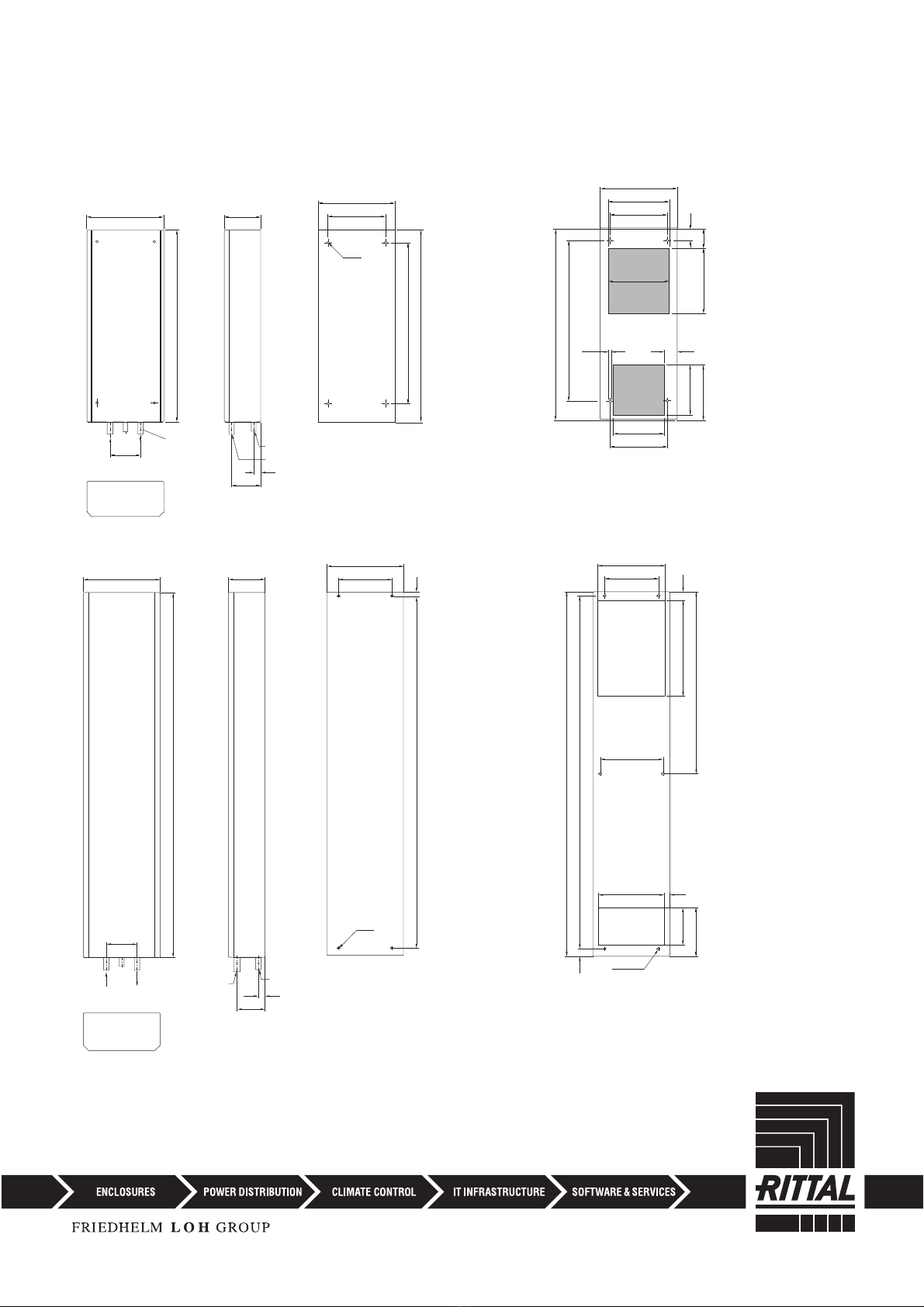
Befestigungsbohrungen Einbau
Fastening holes for internal mounting
Perçages pour montage encastré
Bevestigingsgaten voor inbouw
Montagehålbild, inbyggnad
Fori di fissaggio per installazione incassata
Taladros de fijación para montaje interior
取付穴 全埋め込み取付け
Montageausbruch Anbau
Mounting cut-out for external mounting
Découpe pour montage en saillie
Montage-uitsparingen, aanbouw
Montagehålbild, påbyggnad
Feritoia per installazione sporgente
Escotadura de montaje para montaje exterior
取付用カットアウト 表面取付け
SK 3214.100
SK 3215.100
➀Kondensatablauf
➀Condensate discharge
➀Ecoulement d’eau de condensation
➀Condensafvoer
➀Kondensavlopp
➀Dispositivo di scarico condensa
➀Salida del agua de codensación
➀凝縮水排出器
➁Kühlwasser-Anschluß 1/2˝
➁Cooling water connection 1/2˝
➁ Branchement eau de refroidissement 1/2˝
➁ Aansluiten koelwater 1/2˝
➁ Kylvattenanslutning 1/2˝
➁ Allacciamento liquido frigorigeno 1/2˝
➁ Acometida de 1/2˝ del agua de refrigeración
➁給水部 1/2 インチ
Ø 7
Ø 7
2
air/water heat exchanger
300 451
310
310
310
30
1800
300
11
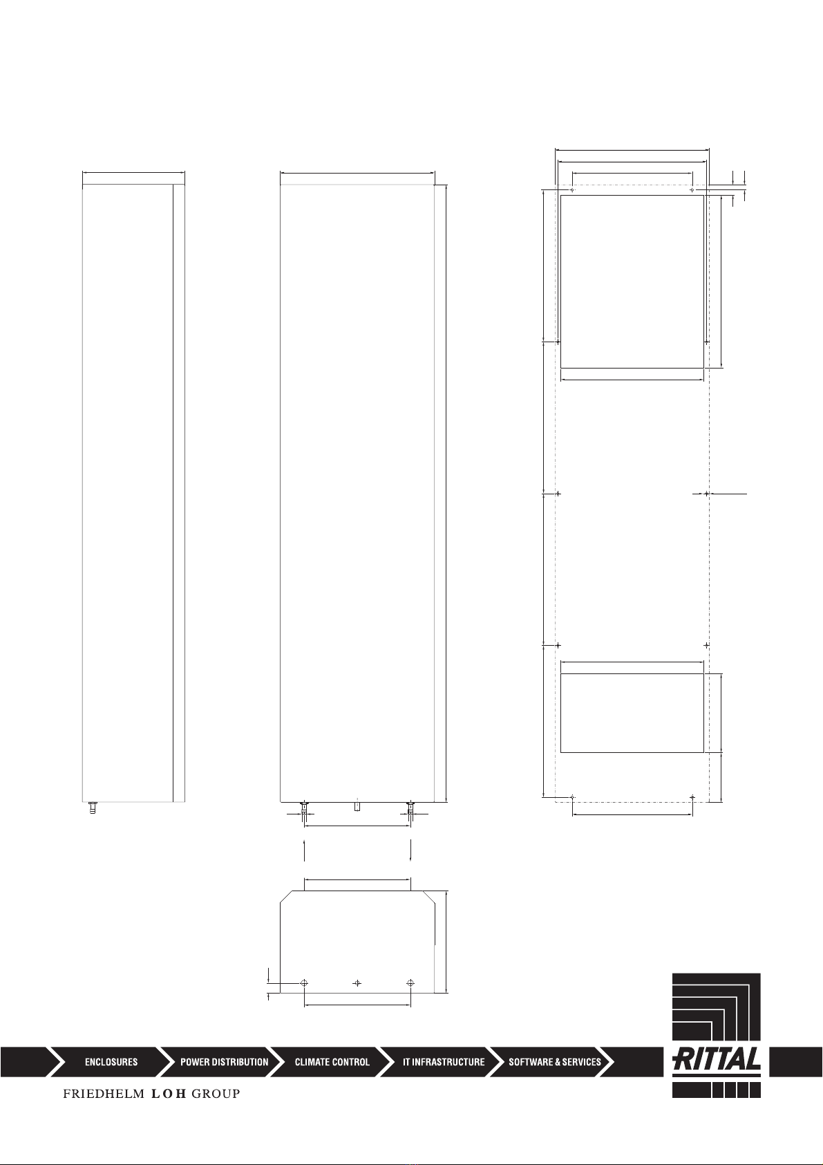
SK 3216.480 451
Ø 8 (10 x)
433.5
350
417
442.5
230
145
442.5 442.5 442.5
530
30
15
417
350
Montageausbruch Anbau
Mounting cut-out for external mounting
Découpe pour montage en saillie
Montage-uitsparingen, aanbouw
Montagehålbild, påbyggnad
Feritoia per installazione sporgente
Escotadura de montaje para montaje exterior
取付用カットアウト 表面取付け
/2w
/2w
3
air/water heat exchanger
300
150
60
➁
➀
85
18
55
300
276
102
150
Ø 7 (4 x)
300
276
232
41
150
125
102
Ø 7 (4 x)
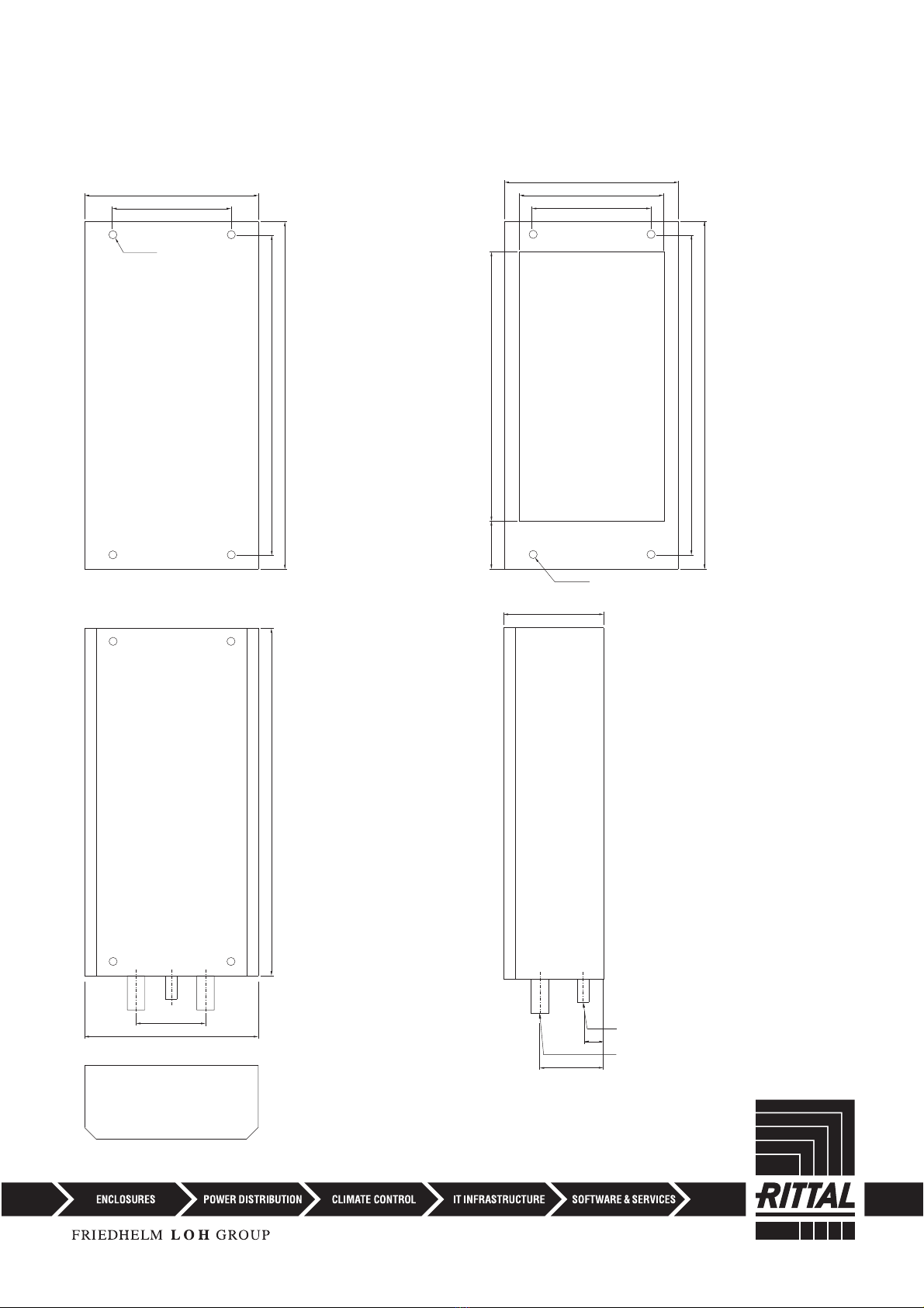
Befestigungsbohrungen Einbau
Fastening holes for internal mounting
Perçages pour montage encastré
Bevestigingsgaten voor inbouw
Montagehålbild, inbyggnad
Fori di fissaggio per installazione incassata
Taladros de fijación para montaje interior
取付穴 全埋め込み取付け
Montageausbruch Anbau
Mounting cut-out for external mounting
Découpe pour montage en saillie
Montage-uitsparingen, aanbouw
Montagehålbild, påbyggnad
Feritoia per installazione sporgente
Escotadura de montaje para montaje exterior
取付用カットアウト 表面取付け
SK 3212.xxx
➀Kondensatablauf
➀Condensate discharge
➀Ecoulement d’eau de condensation
➀Condensafvoer
➀Kondensavlopp
➀Dispositivo di scarico condensa
➀Salida del agua de codensación
➀凝縮水排出器
➁Kühlwasser-Anschluß 3/8˝
➁Cooling water connection 3/8˝
➁ Branchement eau de refroidissement 3/8˝
➁ Aansluiten koelwater 3/8˝
➁ Kylvattenanslutning 3/8˝
➁ Allacciamento liquido frigorigeno 3/8˝
➁ Acometida de 3/8˝ del agua de refrigeración
➁給水部 3/8 インチ
4
air/water heat exchanger

Tab. 2.1 Technische Daten
Tab. 2.1 Technical data
Tab. 2.1 Données techniques
Tab. 2.1 Technische gegevens
Tab. 2.1 Tekniska data
Tab. 2.1 Caratteristiche tecniche
Tab. 2.1 Datos técnicos
図2.1 仕様
Bemessungsbetriebs-
spannung
Bemessungs-
strom
Vor-
sicherung
T
Einschalt-
dauer
Nutzkühlleistung Kühlmedium:
Wasser
(s. Spezifikation)
Wasservorlauf-
temperatur
Umgebungs-
temperatur-
bereich
Betriebs-
druck
Geräusch-
pegel
Schutzart
Innenkreislauf
Außenkreislauf
Abmessungen
(B x H x T)
mm
Gewicht Farbton
Operating
voltage
Rated
current
Pre-fuse
T
Duty cycle Useful cooling
output
Refrigerant:
Water
(see specification)
Water inlet
temperature
Ambient
temperature
Operating
pressure
Noise
level
Protection categ.
Internal circuit
External circuit
Dimensions
(W x H x D)
mm
Weight Colour
Tension
nominale
Courant
nominal
Dispositif
de sécurité
T
Durée de
mise en
circuit
Puissance
frigorifique en
régime permanent
Fluide frigorigène:
de l’eau (voir les
spécifications)
Température de
l’eau à l’entrée
Température
ambiante
Pression
de régime
Niveau
sonore
Ind. de protect.
Circuit intérieur
Circuit extérieur
Dimensions
(L x H x P)
mm
Poids Teinte
Bedrijfs-
spanning
Nominale
stroom
Voor-
zekering,
traag T
Inschakel-
duur
Nuttig
koelvermogen
Koelmedium:
Water
(zie specificatie)
Waterinlaat-
temperatuur
Omgevings-
temperatuur-
bereik
Bedrijfs-
druk
Geluidsnivo Beschermklasse
Inwendig circuit
Uitwend. circuit
Afmetingen
(B x H x D)
mm
Gewicht Kleur
Märkspänning Märkström Försäkring
T
Inkopp-
lingstid
Effektiv
kyleffekt
Kylmedel:
Vatten
(se specifikation)
Tillvatten-
temperatur
Omgivnings-
temperatur
Vattentryck Ljudnivå Kapslingsklass
Inre kretslopp
Yttre kretslopp
Mått
(B x H x D)
mm
Vikt Färgton
Tensione
nominale
Corrente
nominale
Fusibile
ritardato T
Intermit-
tenza
Potenza
frigorifera utile
Mezzo frigorifero:
Acqua
(vedi specifica)
Temperatura
di ingresso
dell’acqua
Campo di
temperatura
d’impiego
Pressione
di
esercizio
Livello di
rumorosità
Grado di protez.
Circuito interno
Circuito esterno
Dimensioni
(L x A x P)
mm
Peso Colore
Tensión
de servicio
Intensidad
nominal
Fusible T Duración
de
conexión
Potencia
frigorífica útil
Agente refrigerante:
Agua
(ver especificación)
Temperatura
del agua de
entrada
Campo de
temperatura
ambiente
Presión
máxima
admisible
Nivel
de ruido
Protección
Circuito interior
Circuito exterior
Dimensiones
(anch. x alt.
x prof.) mm
Peso Color
定格電圧 定格電流 バック
アップ
ヒューズ
デュー
ティサイ
クル
有効冷却能力 冷却材:水
( 冷却材仕様
参照)
注入時水温 外部温度
範囲
動作圧 騒音
レベル
保護等級
内部回路
外部回路
外形寸法
(幅 x 高さ x 奥
行)mm
質量
カラー
L35 W10, 200 l/h
L35 W10, 400 l/h EN 60 529
SK 3212.024
24 V DC, 1,20 A 2,0 A
100% 300 W (200 l/h) > +1°C –
+30°C
+1°C –
+70°C 1 – 10 bar 42 dB (A) IP 55 150 x 300 x 80 3 kg RAL
7035
SK 3214.100
230 V,
50/60 Hz
0,17 A/
0,18 A
2,0 A/
2,0 A 100 % 600 W (200 l/h)
650 W (400 l/h)
> +1°C –
+30°C
+1°C –
+70°C 1 – 10 bar 42 dB (A) IP 55 200 x 500 x 100 7 kg RAL
7035
SK 3217.100
230 V,
50/60 Hz
0,60 A/
0,55 A
4,0 A/
4,0 A 100 % 1000 W (200 l/h)
1100 W (400 l/h)
> +1°C –
+30°C
+1°C –
+70°C 1 – 10 bar 44 dB (A) IP 55 298 x 520 x 135 9,5 kg RAL
7035
SK 3215.100
230 V,
50/60 Hz
0,38 A/
4,0 A
4,0 A/
4,0 A 100 % 1250 W (200 l/h)
1300 W (400 l/h)
> +1°C –
+30°C
+1°C –
+70°C 1 – 10 bar 53 dB (A) IP 55 200 x 950 x 100 13 kg RAL
7035
SK 3216.480
400 V, 3~, 50/60 Hz
480 V, 3~, 60 Hz
1,4 A/1,6 A
1,2 A
4,0 A/
4,0 A 100% 7000 W (500 l/h) > +1°C –
+30°C
+1°C –
+70°C 1 – 10 bar 70 dB (A) IP 55 450 x 1800 x 300 79 kg RAL
7035
D
GB
F
NL
S
I
E
J
5
air/water heat exchanger

English
4. Electrical connection
The connection voltage and frequency must cor-
respond to the rated values quoted on the data
plate. The unit must be connected to the mains
via a disconnection device which ensures at least
3 mm contact opening in the deactivated state.
No additional temperature control must be con-
nected to the supply side of the unit. Line protec-
tion should be provided by means of the pre-fuse
specified on the name plate. Please observe the
relevant regulations when installing!
The mains connection is made at the connec-
tion terminal
5. Cooling water
connection
The cooling water connection must be made with
pressure resistant flexible hoses which should be
secured with clips.
(Note the direction of flow and check for
absence of leaks!)
The units have no separate air-bleed. With
pressure-sealed systems, corresponding air-
bleed facilities are to be installed on the water
side.
Protect the water circuit from contamination and
excess pressure (10 bar max.).
Please observe the relevant regulations when
installing!
6. Refrigeration and
control behaviour
The fan of the air circuit operates continuously,
thus ensuring an even temperature distribution
within the enclosure. A solenoid valve controls the
cooling water flow in accordance with the preset
temperature. Setting range +20°C to +60°C.
Presetting of the enclosure temperature is made,
6.1 for SK 3214.100 / SK 3215.100 /
SK 3216.480
via the thermostat on the rear of the unit.
6.2 SK 3212.xxx has no control unit.
7. Leaks and temperature
monitoring
7.1 Temperature monitoring
Should the temperature inside the enclosure rise
by more than
10 K in the models SK 3214.100 / SK 3215.100
SK 3216.480
For SK 3214.100 / SK 3215.100 / SK 3216.480
the connection of the potential-free contact is
made via the plug-in terminal strip on the rear of
the unit.
7.2 Leak monitoring
In the event of a leakage developing
a pipe fracture occurring in the water circuit
a) the cooling water supply will be cut
off immediately,
b) the potential-free changeover contact will
be switched, and
c) the fan will be switched off.
8. Maintenance
The air/water heat exchangers require no main-
tenance (see point 12.).
Check the function of the condensate draining
facility regularly.
9. Scope of supply
and warranty
3212.xxx / SK 3214.100 / SK 3215.100 /
SK3216.480
1 air/water heat exchanger, ready for connection
1 sealing tape
4 fastening bolts
(internal installation of unit 3247.000)
4 threaded pins M6 x 30
(internal installation of unit)
4 flat-headed screws M6*
4 fixing rings*
4 nuts M6
4 washers A 6.4
4 protective caps
1 set of assembly and operating instructions
1 drilling template
* Only for SK 3214.100 / SK 3215.100 /
SK 3216.480
instead of the threaded pins.
Guarantee:
This unit is covered by a 1-year guarantee from
the date of supply, subject to correct usage.
Within this period, the returned unit will be
repaired in the factory or replaced free of charge.
The unit is to be used for the cooling of enclosures
only. If it is connected or handled improperly the
manufacturer’s guarantee does not apply and in
this case we are not liable for any damage
caused.
Contents
1. Application
2. Technical data
3. Assembly
4. Electrical connection
5. Cooling water connection
6. Refrigeration and control behaviour
7. Leaks and temperature monitoring
8. Maintenance
9. Scope of supply and warranty
10. Safety instructions
11. Notes on water quality
12. Spares lis
1. Application
Air/water heat exchangers are designed and
built to dissipate heat from enclosures, by cool-
ing the air inside the enclosure and protecting
temperature sensitive components. Air/water
heat exchangers are particularly suitable for the
temperature range of +40°C to +70°C, where for
system related reasons, comparable units such
as air/air heat exchangers, enclosure cooling
units or fan units with filters cannot be used to
dissipate heat effectively and economically.
2. Technical data
(see table 2.1).
3. Assembly
Please use the enclosed drilling template to cut
out the component apertures.
SK 3212.230 / SK 3214.100 / SK 3215.100 / SK
3216.480
External installation of the unit
Screw the four fastening bolts ➀, together with
the washer ➁and nut ➂, to the mounting level
➃ of the enclosure. Push the heat exchanger ➄
into position and secure with four screws ➅.
Internal installation of the unit (Fig. page 30):
Insert four fastening bolts ➀into the appliance
from behind. Slide the fixing ring ➆onto the
fastening bolts as a mounting aid. Screw the
appliance, together with the washer ➁and nut
➂, to the mounting level of the enclosure from
the outside. Push the protective cap ➇onto the
nut.
10. Safety instructions
● When installing the device, the condensate
discharge must be routed out of the enclosure!
● In order to avoid frost damage, the minimum
permissible water temperature of +1°C must
not be undercut at any point in the water cycle!
● It is essential to obtain the manufacturer’s
permission before adding anti-freeze!
● During storage and transportation below
freezing point, the water cycle should be
drained completely using compressed air!
● Only set the thermostat as low as is strictly
necessary, because of undercutting the dew
point with a falling water inlet temperature
(condensation)!
● It is very important that the enclosure is sealed
on all sides (IP 54), particularly the cable entry
(condensation)!
6
air/water heat exchanger

11. Notes on water quality For safe operation of the
equipment, it is essential to observe the VBG guidelines on cooling water (VGB
R 455 P).
Cooling water must not contain any limescale deposits or loose debris; in other
words, it should have a low level of hardness, particularly a low level of carbon
hardness. For recooling within the plant, the carbon hardness should not be too
high. On the other hand, however, the water should not be so soft that it attacks
the operating materials. When recooling the cooling water, the salt content
should not be allowed to increase excessively due to the evaporation of large
quantities of water, since electrical conductivity increases as the concentration
of dissolved sub-stances rises, and the water thereby becomes more corrosive.
For this reason, not only is it always necessary to add a corresponding quan-tity
of fresh water, but also to remove part of the enriched water.
Gypsiferous water is unsuitable for cooling purposes because it has a
tendency to form boiler scale, which is particularly difficult to remove.
Furthermore, cooling water should be free from iron and manganese,
because otherwise deposits may occur which settle in the pipes and
block them. At best, organic substances should only be present in
small quantities, because otherwise sludge deposits and
microbiological contamination may occur.
12.1 Preparation and maintenance
of the water in recooling systems
Depending on the type of installation to be cooled, certain
requirements are placed on the cooling water with respect to purity.
According to the level of contamination and the size and design of the
recooling systems, a suitable process is used to prepare and/or
maintain the water. The most common types of contamination and most
frequently used techniques to elimin-ate them in industrial cooling are:
Contamination of the water Procedure
Mechanical contamination
Filtering of water via
– Mesh filter
– Gravel filter
– Cartridge filter
– Precoated filter
Excessive hardness Water softening via ion exchange
Moderate content of mechanical contaminants
and hardeners Addition of stabilisers and/or dispersing
agents to the water
Moderate content of chemical contaminants Addition of passifiers and/or inhibitors
to the water
Biological contaminants, slime bacteria and algae Addition of biocides to the water
In order to ensure correct operation of a recooling system which is operated with water on at least one side, the properties of the
added or system
SK 3212.xxx / SK 3214.100 /
SK 3215.100 / SK 3216.480
Hydrological data
pH value 7 – 8.5
Carbonate hardness > 3 < 8 °dH
Free carbon dioxide 8 – 15 mg/dm3
Accompanying carbonic acid 8 – 15 mg/dm3
Aggressive carbonic acid 0 mg/dm3
Sulphides free
Oxygen < 10 mg/dm3
Chloride ions < 50 mg/dm3
Sulphate ions < 250 mg/dm3
Nitrates and nitrites < 10 mg/dm3
COD < 7 mg/dm3
Ammonia < 5 mg/dm3
Iron < 0.2 mg/dm3
Manganese < 0.2 mg/dm3
Residue on evaporation < 500 mg/dm3
Potassium permanganate consumption < 25 mg/dm3
Suspended matter
< 3 mg/dm3
> 3 < 15 mg/dm3part current purification recommended
> 15 mg/dm3continuous purification recommended
water used should not deviate substantially from the following list of hydrological data:
1) The complete absence of corrosion under experimental conditions suggests that solutions with a
significantly higher salt content and greater corrosion potential (such as seawater) may still be
tolerated.
7
air/water heat exchanger

Ersatzteil-
liste Spares
list
Liste de
pièces
détachées
Lijst
reserve-
delen
Reserv-
delslista
Lista dei
pezzi di
ricambio
Lista de
piezas de
repuesto
スペア
パーツ
Bezeichnung Description Signification Benaming Beteckning Descrizione Descripción 製品名
10 Ventilator,
komplett Fan,
complete Ventilateur,
complète Ventilator,
kompleet Fläkt,
komplett Ventilatore,
completa Ventilador,
completo ファン、
一式
15 Zubehörbeutel Dispatch bag Pochette
d’accessoires Zakje toebehoren Tillbehörspåse Sacchetto
accessori Bolsa de
accesorios アクセサリー
バッグ
16 Abdichtplatte Sealing plate Plaque
d’étanchéité Afdichtplaat Tätningsplatta Piastra di tenuta Placa de
estanqueidad 密閉用プレート
32 Magnetventil,
komplett Solenoid valve,
complete Vanne électroma-
gnétique, complète Magneetventiel,
kompleet Magnetventil,
komplett Valvola elettromag-
netica, completa Electroválvula,
completa マグネットバルブ、
一式
33 Rückschlagventil Flap valve Clapet antiretour Terügstroomventiel Backventil Valvola di
non ritorno Válvula de
retención フラップバルブ
35 Zwei-Stufen-
Thermostat Two-stage
thermostat Thermostat
à deux paliers Tweestanden-
thermostaat Tvåstegs-
termostat Termostato
a due stadi Termostato
de dos estados 二段階式
サーモスタット
40 Steuerplatine
komplett Control PCB
complete Platine de com-
mande, complète Stuurstroomprint,
kompleet Styrkort,
komplett Piastra circuito
stampate, completa Pletina de mando
completa コントロールPCB、
一式
48 Lufteintrittsgitter Air inlet grille Grille d’entrée d’air Luchtinlaatrooster Luftingångsgaller Griglia d’entrata
dell’aria Rejilla de entrada
de aire 吸気グリッド
71 Temperaturfühler Temperature
sensor Sonde de
température Temperatuursensor Temperaturgivare Sonda di
temperatura Sonda térmica 温度センサー
73 Leckagesensor Leakage sensor Palpeur de fuite Lekkagesensor Läckagesensor Rivelatore
di perdite Sensor de fugas
de agua 漏水モニター
75 Haube,
komplett Cover,
complete Couvercle,
complète Afdekkap,
kompleet Huv,
komplett Calotta,
completa Cubierta
completa カバー、
一式
91 Wärmetauscher Heat exchanger Echangeur
thermique Warmtewisselaar Värmeväxlare Scambiatore
di calore Intercambiador
de calor ヒートエクスチェン
ジャー
95 Bodenwanne,
komplett Base tray,
complete Bac de rétention,
complète Bodemplaat,
kompleet Bottentråg,
komplett Vaschetta di racc.
cond., completa Bandeja de base
completa ベーストレイ、
一式
DEJ
GB NL I
FS
Position
Item
Pos.
Pos.
Pos.
Pos.
Posición
項目
Bei Bestellung unbedingt angeben
Typ:
Fabrikations-Nr.:
Herstelldatum:
Ersatzteil-Nr.:
Absolutely necessary in case of order
Type:
Fabrication no.:
Manufacturing date:
Spare part no.:
スペアパーツご発注時に必ずご記入下さい。
クーラー型式:
製造番号:
製造日時:
スペアパーツ番号:
12. Spares list
8
air/water heat exchanger
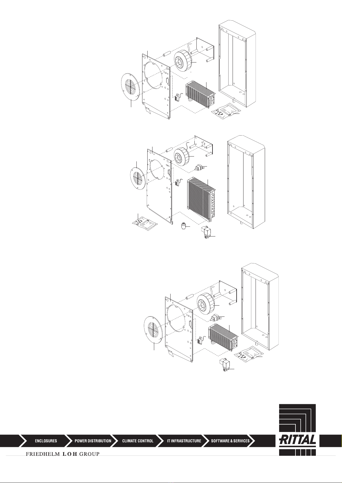
32
33
35
91
48
15
10
75
SK 3216.480
75
10
91
48
15
SK 3212.xxx
SK 3212.230 / SK 3214.100 /
SK 3215.100
32
75
10
35
91
48
15
*
*
9
air/water heat exchanger

6514283271
5
4
Geräteanbau
External mounting
Montage en saillie
Apparaatopbouw
Påbyggnad
Montaggio sporgente
Montaje exterior del aparato
表面取付け
Geräteeinbau
Internal mounting
Montage encastré
Apparaatinbouw
Inbyggnad
Montaggio incassato
Montaje interior del aparato
全埋め込み取付け
3
Geräteanbau
External mounting
Montage en saillie
Apparaatopbouw
Påbyggnad
Montaggio sporgente
Montaje exterior del aparato
表面取付け
Geräteeinbau
Internal mounting
Montage encastré
Apparaatinbouw
Inbyggnad
Montaggio incassato
Montaje interior del aparato
全埋め込み取付け
Abb. 3.2 Anbringung der Dichtung
Fig. 3.2 Attaching the seal
Fig. 3.2 Mise en place du joint
Afb. 3.2 Aanbrengen van de afdichting
Bild 3.2 Montage av tätning
Fig. 3.2 Applicazione della guarnizione
Fig. 3.2 Colocación de la junta
図3.2 パッキンの取付
SK 3212.xxx / SK 3214.100 /
SK 3215.100 / SK 3216.480
SK 3212.xxx / SK 3214.100 /
SK 3215.100 / SK 3216.480
SK 3212.xxx / SK 3214.100 /
SK 3215.100 / SK 3216.480
SK 3212.xxx / SK 3214.100 /
SK 3215.100 / SK 3216.480
10
air/water heat exchanger
SK 3212.230
Anschlußplan
Wiring diagram
Schéma des connexions
Aansluitschema
Anslutningsdiagram
Schema di allacciamento
Esquema de conexiones
配線図
024
M
1~
C1
M1
X10
L1 N
X11
X20
SK 3212.230
Anschlußplan
Wiring diagram
Schéma des connexions
Aansluitschema
Anslutningsdiagram
Schema di allacciamento
Esquema de conexiones
配線図
230
11
air/water heat exchanger

1~
32
X10 3
C1
F1.2
Y1
14
31
T
34
M1
45
X20
X10
L1 N
T
11
F1.1
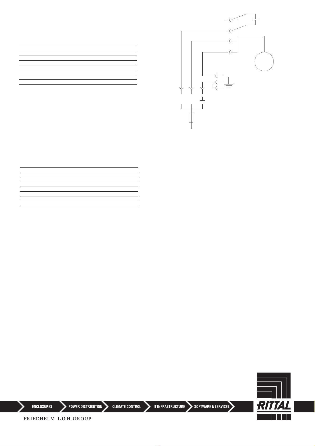
SK 3214.100 / SK 3215.100
Wiring diagram
Schéma des connexions
Aansluitschema
Anslutningsdiagram
Schema di allacciamento
Esquema de conexiones
配線図
Technische Daten siehe Typenschild
Technical data see name plate
Données techniques voir plaque signalétique
Technische gegevens zie typeplaatje
Tekniska data se typskylten
Caratteristiche tecniche vedi dati di targa
Datos técnicos ver placa de características
仕様については銘板参照
M
SK 3216.480
Anschlußplan
Wiring diagram
Schéma des connexions
Aansluitschema
Anslutningsdiagram
Schema di allacciamento
Esquema de conexiones
配線図
12
air/water heat exchanger
Anschlußschema
A1 = Steuerplatine
B1 = Temperaturfühler
B2 = Leckagefühler
C1 = Betriebskondensator
F1 = Thermostat
F1.1 = Schaltkontakt
F1.2 = Störmeldekontakt
M1 = Ventilator
Y1 = Magnetventil
X1 = Klemmleiste
X10 = Stecker Netzanschluß (schwarz)
X11 = Stecker Sammelstörmeldung (braun)
X12 = Gerätesteckanschluß TW
X20 = Steckverbindung Ventilator
P1 = Sollwert-Potentiometer
Schrankinnentemperatur
ABC = Umschaltung der Betriebsart
Aansluitschema
A1 = Stuurstroomprint
B1 = Temperatuursensor
B2 = Lekkagesensor
C1 = Bedrijfskondensator
F1 = Thermostaat
F1.1 = Schakelaar
F1.2 = Storingsmelderkontakt
M1 = Ventilator
Y1 = Magneetventiel
X1 = Klemmenstrook
X10 = Stekker netaansluiting (zwart)
X11 = Stekker verzamelsfoormelding
(bruin)
X12 = Connectoraansluiting TW
X20 = Connector voor ventilator
P1 = Temperatuur in kast
ABC = Omschakeling van bedrijfsstand
Esquema
de conexiones
A1 =
Pletina de mando
B1 =
Sensor de temperatura
B2 =
Sensor de fugas
C1 =
Condensador de servicio
F1 = Termostato
F1.1 = Contacto de conexión
F1.2 = Contacto de aviso de averia
M1 =
Ventilador
Y1 = Válvula electromagnética
X1 = Regleta de bornes
X10 = Enchufe alimentación de red (negro)
X11 = Enchufe aviso de avería colectiva
(marrón)
X12 = Conexión de enchufe del aparato TW
X20 = Conexión ventilador
P1 = Valor teórico potenciómetro
temperatura interior armario
ABC =
Conmutación de la clase de servicio
D
NL
E
Wiring diagram
A1 = Control PCB
B1 = Temperature sensor
B2 = Leak sensor
C1 = Operating capacitor
F1 = Thermostat
F1.1 = Switch contact
F1.2 = Fault signal contact
M1 = Fan
Y1 = Solenoid valve
X1 = Terminal strip
X10 = Mains plug connector (black)
X11 = Collective fault signal plug (brown)
X12 = Unit plug connector TW
X20 = Plug connection fan
P1 = Set-point setter,
enclosure internal temperature
ABC = Changeover of operating mode
Anslutningsschema
A1 = Styrkort
B1 = Temperaturavkännare
B2 = Läckageavkännare
C1 = Driftkondensator
F1 = Termostat
F1.1 = Omkopplare
F1.2 = Felmeddelande
M1 = Fläkt
Y1 = Magnetventil
X1 = Klämlist
X10 = Kontakt nätanslutning (svart)
X11 = Kontakt störsignaler (brun)
X12 = Aggregatuttag TW
X20 = Anslutning fläkt
P1 = Apparatskåpets innertemperatur
ABC = Växling av funktion
配線図
A1 = 制御PCB
B1 = 温度センサー
B2 = 漏水センサー
C1 = 操作用コンデンサー
F1 = サーモスタット
F1.1 = スイッチ接点
F1.2 = エラー信号接点
M1 = ファン
Y1 = マグネットバルブ
X1 = ターミナルストリップ
X10 = 電源プラグ(黒)
X11 = 集合故障信号プラグ(茶)
X12 = ユニットプラグコネクタ TW
X20 = プラグ接続式ファン
P1 = 設定値ポテンシャルメータ
エンクロージャー内部温度用
ABC = 運転モード切替
GB
S
J
Schéma électrique
A1 = Platine de commande
B1 = Sonde de température
B2 = Sonde de niveau d’eau
C1 = Condensateur de régime
F1 = Thermostat
F1.1 = Contact de commutation
F1.2 = Contact de signalisation de défaút
M1 = Ventilateur
Y1 = Vanne électromagnétique
X1 = Bornier
X10 = Bornes de raccordement secteur (noir)
X11 = Bornes de raccordement des
indications de défaut (brun)
X12 = Connecteur enfichable TW
X20 = Fiche du ventilateur
P1 = Potentiomètre de réglage de la
température intérieure de l’armoire
ABC =
Commutation du mode
de fonctionnement
Schema allacciamenti
A1 = Piastra circuito stampate
B1 = Sonda di temperatura
B2 = Rivelatore (sonda) di predita
C1 = Condensatore d’esercizio
F1 = Termostato
F1.1 = Contatto degli interruttori
di distribuzione
F1.2 = Contatto di segnalazione guasti
M1 = Ventilatore
Y1 = Valvola elettromagnetica
X1 = Morsettiera
X10 =
Spina allacciamento rete (nero)
X11 =
Spina circuito de segnalazione
(marrone)
X12 = Allacciamento apparecchio TW
X20 = Connettore per ventilatore
P1 = Regolazione della temperatura interna
ABC = Commutazione del tipo esercizio
F
I
13
air/water heat exchanger
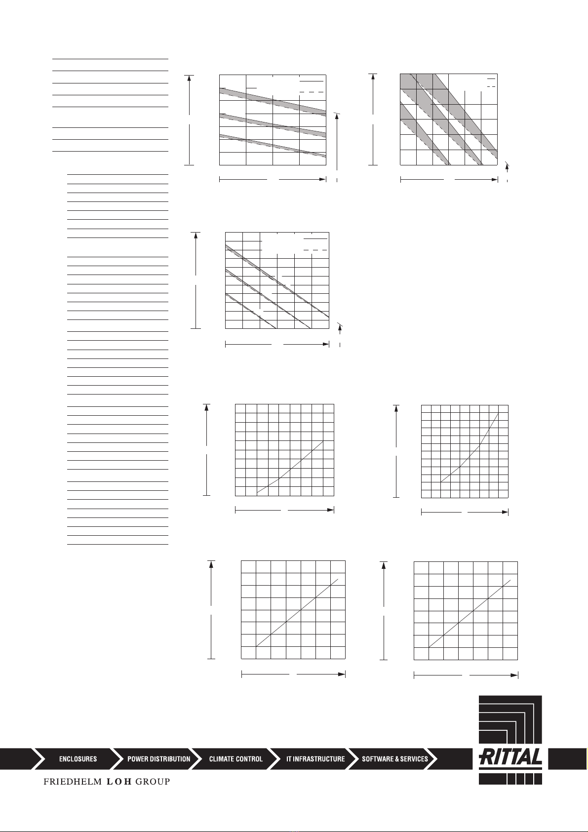
Kennlinienfeld (DIN 3168)
Performance diagram
Diagramme aéraulique
Karakteristiek
Karakteristik kurva
Diagramma delle curve
caratteristiche
Diagrama de potencia
動作性能表
700
600
500
400
300
200
100
10 15 20
QK
.
TW
Ti
VW= 400 l/h
.
VW= 200 l/h
.
45 °C
35 °C
25 °C
5
1000
10 15 20 25 3530
2000
3000
4000
5000
6000
7000
45 °C
35 °C
25 °C
QK
.
TWTi
VW
= 500 l/h
VW
= 400 l/h
.
.
ΔP
V
200100 300 400
800
600
400
200
1000
.
ΔP
V
200100 300 400
1000
800
600
200
400
1200
.
Dauer-Nutzkühlleistung [W]
Continuous useful cooling output
Puissance frigo. en régime permanent
Nuttig koelvermogen
Kyleffekt
Potenza frigorifera utile
Potencia útil de refrigeración
冷却能力
Q
·K=
Schaltschrank-
Innentemperatur [°C]
Enclosure internal temperature
Température à l’interieur de l’armoire
Temperatuur in de kast
Temperatur inne i skåpet
Temperatura interna dell’armadio
Temperatura interior armario
エンクロージャー内部温度
Ti=
Wassereintrittstemperatur [°C]
Water inlet temperature
Température de l’eau à l’entrée
Waterinlaattemperatuur
Vattnets ingångstemperatur
Temperatura d’ingresso dell’acqua
Temperatura de entrada del agua
注入時水温
Tw=
Kennlinienfeld SK 3216.480
(DIN 3168) (50/60 Hz)
Volumenstrom [l/h]
Volume flow
Débit d’air
Volumestroom
Volymström
Portata
Caudal volumétrico
水量
V
.=
Wasserwiderstand [m/bar]
Water resistance
Résistance hydraulique
Waterweerstand
Vattenmotstånd
Resistenza dell’acqua
Resistencia del agua
耐水圧
6P=
Kennlinienfeld SK 3212.xxx
(DIN 3168) (50/60 Hz)
Wasserwiderstandskennlinie
SK 3216.480
Wasserwiderstandskennlinie
SK 3212.xxx
2400
2200
2000
1600
1400
1200
1000
800
600
400
200
510 15 20 25 30 35
45°C
35°C
25°C
VW= 400 l/h
.
VW= 200 l/h
.
QK
.
TW
Ti
Kennlinienfeld SK 3215.100
(DIN 3168) (50/60 Hz)
ΔP
V
.
300 400 500
300
200
100
400
ΔP
V
.
200 300 400
300
200
100
400
Wasserwiderstandskennlinie
SK 3214.100
Wasserwiderstandskennlinie
SK 3215.100
14
air/water heat exchanger

◾Enclosures
◾ Power Distribution
◾ Climate Control
◾ IT Infrastructure
◾ Software & Services
You can find the contact details of all
Rittal companies throughout the world here.
www.rittal.com/contact
RITTAL GmbH & Co. KG
Postfach 1662 · D-35726 Herborn
Phone +49(0)2772 505-0 · Fax +49(0)2772 505-2319
6st edition 07 / 2019 / ID no. 239952
15
air/water heat exchanger
This manual suits for next models
3
Table of contents
Popular Water Heater manuals by other brands

Galmet
Galmet SGW 120 Installation and operating manual / warranty card

AquaStar
AquaStar 80 VP Install and operation instructions

AEG
AEG U5 Operation and installation

Qtermo
Qtermo TREND 50 CERAMIC MANUAL FOR INSTALLATION, OPERATION AND MAINTENANCE

EDN
EDN RADIASOL T150 Technical manual

Bradford White
Bradford White 50T Specification sheet

WarmFlow
WarmFlow Cylinder Passport User instructions

Invest
Invest ISP 2.0 installation manual

Enviroheat
Enviroheat 200EH1-14 Operation and installation manual

Nibe
Nibe VPB 500 User's and installer's manual

Rheem
Rheem Gas Domestic Indoor Water Heater Installation and owner's guide

Noritz
Noritz GQ-C2857WS-FF US installation manual


