Franke OMNI 4in1 User manual

2
FRANKE OMNI 4in1
BOILING WATER SYSTEM
Installation instructions

2
ON
OFF
HOT
COLD
The Franke Omni System must be installed using only the
genuine Franke items listed below. Substituting any of the
above 3 items for non-Franke manufactured alternatives, or
failing to install and maintain the unit in strict accordance with
these instructions, will invalidate your product warranty.
Franke will not accept liability for damage or accidents
resulting from the use of non-genuine Franke components,
incorrect installation or operation.
Application
This product is a boiling water device intended for domestic
use only. The water supply pressure must be between
minimum 1.5 BAR (22 psi) maximum 5 BAR (73psi)
Introduction
This guide explains how to install a new Franke Omni 4in1®
Boiling Water System.
Thank you for purchasing a Franke Omni Tap System. In
keeping with Franke’s worldwide reputation this product has
been designed and manufactured to the very highest quality
standards. Correctly installed and properly maintained in
accordance with the following instructions, it will provide you
with reliable service for many years.
The Franke Omni System comprises 3 separately packaged
assemblies:
1. Franke 4in1 Omni tap (Part Number: 119.0380.520)
2. Franke boiler - Model QHT-1 (Part Number: 119.0380.581)
3. Franke water filter complete with a Franke 08 filter
cartridge. (Part Number: 119.0380.582)
Please Note: This diagram is for guidance only

3
Boiler technical data
Description Value Unit
Dimensions 230 x 182 x 354 mm
Load 10 Amps
Voltage 230 Volts
Power 1500 Watts
Stored Temperature 105 °C
Min Water Pressure 1.5 Bar
Max Water Pressure 5 Bar
Heating Up Time 20 Mins
Recovery Time 10 Mins
Boiler Capacity 4 Litres
Pressure Release Valve Rating 8 Bar
Before you begin
1. Check the mains water pressure. The pressure must not
be below 1.5 BAR (22 psi) or above 5 BAR (73psi),
measured during a low demand period – (mid-morning or
mid-afternoon). If the pressure exceeds 5 BAR a pressure
reducing valve must be installed in the cold mains supply
to protect both the boiler and the water filter housing. A
suitable pressure reducing valve can be purchased at
www.frankefilterflow.co.uk.
2. The unit must be installed in a frost free environment.
3. Ensure that the cabinet is well ventilated. If in doubt it is
advisable to improve the circulation of air by drilling some
holes in the top and bottom of the rear panel.
4. Be careful when making the various connections to the
mains water stop valve and the boiler. Do not be tempted
to over-tighten the connections. It is only necessary to
firmly hand tighten the nuts using the patented
NutRunna®plastic tightening devices provided to make a
secure watertight seal.
5. Locate the existing hot and cold water supply pipes.
6. Shut off the mains water supply.
7. Switch off the mains electricity supply at the socket.
Safety
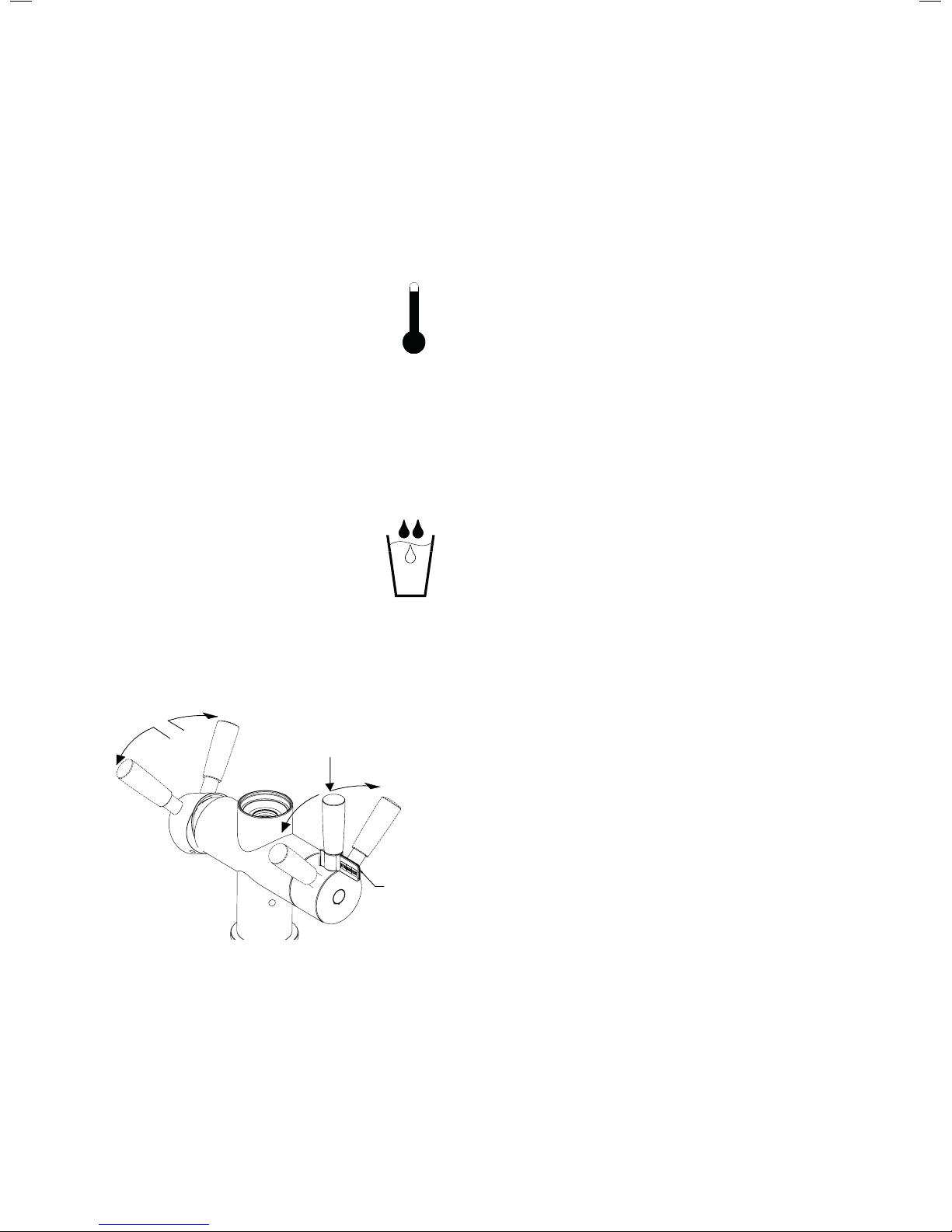
Remember: Boiling water is potentially dangerous and great
care should be exercised when using the Franke Omni tap.
The installation must be carried out by a suitably qualified
professional in strict accordance with the instructions
provided and comply with the UK Water Supply (Water
Fittings) Regulations 1999 and safety standards.
• If a new electrical power supply is required you must
seek the services of a qualified electrician.
• The boiler must only be connected to the 230V mains
electricity supply through either an earthed independent
wall socket or a fused spur.
• The boiler is fitted with an electrical lead terminating in
a UK 3 pin fused plug for connection to the 230 volt 13
amp domestic electricity supply. It is important to use a
socket with a built in switch and position it to provide
convenient access to switch off the boiler.
• Turn off the mains water supply before commencing
installation.
• Never lift the boiler by the flexible connector hoses.
• The power to the boiler must only be switched on once
the installation is complete and the tank is full of water.
• Always turn off the electricity supply to the boiler before
you close the mains stop valve. Restore power to the
boiler after the mains stop valve has been opened.
• Young people and potentially vulnerable users must
be instructed how to operate the boiling water function
safely by a responsible adult.
• This is a domestic appliance and must not be installed in
a commercial environment.
• If the supply cord is damaged it must be replaced by
the manufacturer, an official service agent or similarly
qualified persons in order to avoid a hazard.

4
Component list
1. Franke Omni 4in1 tap
2. Filter Cartridge change indicator module
3. Safety clip for boiling water handle
4. AA Batteries for filter cartridge change
indicator module x2
5. Tap clamp
6. Tap clamping nut x2
7. Box spanner for tap clamp nuts
8. Compression washer for underside of tap
9. Cable ties x4
10. NutRunna®hand-tightening device for
G¼” nuts x2
11. NutRunna®hand-tightening device for
G½” nuts x4
12. Franke QHT-1 boiler
13. Push-fit elbow
14. Tapered silicone washer for boiling water
outlet. (red sticker)
15. Flat silicone sasher for boiler water inlet.
(green sticker)
16. Vent assembly
17. Saddle clamp
18. Vent hose
19. Vent assembly elbow
20. Pipe cutter
21. Water filter housing assembly
22. Franke 08 water filter cartridge
23. Stop valve
24. Water filter retaining screws
Supplied in box with tap
Supplied in box with boiler
Supplied in box with filter system
A
B
C
D
A
G1/2" x2
B
Stem Elbow
C
G1/4"
D
LED Plug
AA
x2
x4 x2 x4
x2
1 2 3
4 5
6 7 8
119 10
233mm
182mm
352mm
80mm Min clearance
A
B
A
Straight Stem
B
G1/2"
12 13 14
15
17
16
18
19 20
A
B
A
G1/2"
B
G1/4"
x3
Flow
21 22
23 24

5
THE INSTALLATION PROCEDURE
Install the Franke Omni 4in1 kitchen tap
Carrying out this operation first will make it easier to plan
the layout inside the cabinet. For safety, it is advisable to
locate the tap at, or towards, the back of the sink out of
reach of smaller children.
1. The tap will require a standard 35mm diameter hole
drilled in the kitchen work surface. Important note:
before drilling the hole make sure that there is enough
clearance between the tap handles and the back splash
when the handles are in the fully open position.
2. Insert the flexible hoses and the wire lead through the
35mm hole.
Position the tap for the owners convenience. (The tap
can be rotated 180° for left handed operation of the
boiling water function).
3. Working inside the cabinet, slide the gasket (8) and the
clamp plate (5) over the hoses and the two studs at the
base of the tap. Screw the two clamp nuts (6) on to the
studs using the box spanner (7).
4. Check the alignment of the tap then tighten the two
clamp nuts using the box spanner to firmly secure it on
the work surface.
Plan the layout inside the cabinet
• Determine the best positions for the hot and cold mains
water supply.
• Determine the best positions for the boiler and the filter
unit, making sure that the boiler power cable, the flexible
hoses, and the filter cartridge change indicator cable, are
all within comfortable reach of their respective
connection points without them being compressed,
stretched or kinked.
• The boiler must be installed upright with the hose
connections at the top, never on its side.
• Allow a minimum clearance of 80mm at the top of the
boiler for the connecting hoses.
• Choose a location for the filter unit (21) and the stop
valve (23) to allow convenient access for future filter
cartridge changes.
SCALE 1 : 2
240mm
Min
100mm
235mm
385mm
35mm
60mm Max

6
The plumbing
Provide a hot and cold water supply for the tap. (We
recommend that service stop-valves are fitted in both the hot
and cold water supplies to the tap).
1. Tee off the cold mains water supply to provide an
independent feed to the water filter.
2. Install the stop-valve (23) inline on the independent feed
to the filter. Important note: the ends of the stop valve
are different. One end has an internal chamfer to connect
to compression pipework; the opposite end has a flat
washer face to suit the G½” (½” BSP) nut and washer of a
flexible hose (refer to diagram (23) in component list).
3. Connect the hot and cold G½” flexible hoses to the
respective hot and cold supplies and tighten them firmly
to make a watertight seal — two G½” NutRunna®hand
tightening devices (11) are supplied loose with the tap for
this purpose. The tap hose with the blue indicator should
be connected to the cold supply and the hose with the
orange indicator to the hot supply.
Install the filter unit
Important note: The filter unit must be installed inside a
cupboard. Long term exposure to direct light can degrade the
plastic sump leading to eventual failure.
1. Position the filter unit (21) vertically with the hoses at the
top, in its previously determined location.
2. Mark the positions for the two filter unit support screws
(24) using the holes in the filter bracket as a guide.
3. Set the filter unit aside and screw in the two screws
leaving the heads slightly proud (approximately 4mm).
4. Take the G½”nut (21.A) at the free end of the filter inlet
hose (blue indicator) and screw it on the G½” male outlet
thread of the stop valve (23). Hand tighten the nut firmly
using the attached NutRunna® (11) sufficient to make a
watertight seal. Do not overtighten.
5. Take the grey push fit stem elbow at the free end of the
cold filtered water hose attached to the tap, wet the stem
before pushing it firmly into the female outlet at the top
of the filter. Important note: ensure that the stem
connector is pushed fully home — 10mm of the stem
should enter the female connector.
6. Hang the filter unit on the two screws. If the panel is too
thin to mount the filter securely strengthen the panel with
a wooden batten.
Cold water
inlet from
filter stop valve
Filtered water
outlet to tap
Filtered
water
outlet
to boiler
Pressure relief
button
Filtered water
outlet to tap
Filtered water
outlet to boiler
Pressure relief
button
Cold water
inlet from
filter stop valve

7
Install the plastic vent assembly
Important note: The vent pipe must be installed vertically
with the air-gap at the top. The vent pipe conforms to the
building regulations and on no account should be shortened
or modified in any way.
1. Choose a convenient position to fit the saddle clamp (17)
preferably on a vertical section (Option 1) of the waste
pipe, or alternatively on a horizontal section (Option 2).
When installing the saddle clamp horizontally the elbow
(19) is not required. Be careful to allow sufficient
clearance for the height of the vent assembly and enough
room to operate the pipe cutter (20).
2. Separate the two halves of the saddle clamp by
unscrewing and removing the four nuts and bolts. Discard
the two black rubber inserts for 41mm waste pipe. Leave
them in place for 32mm pipe.
3. Place the saddle clamp in position on the chosen section
of waste pipe and re-assemble the clamp. Tighten the
nuts and bolts securely to make a watertight seal.
4. Insert the pipe cutter (20) into the saddle clamp and cut
a hole in the waste pipe by rotating it to the right until it
breaks through. (see diagram.)
5. Screw the vent assembly (16) into the saddle clamp. When
the saddle clamp is installed on a vertical section of the
waste pipe screw the elbow in first and use the lock nut to
secure the air gap assembly in the vertical position.
6. Take the vent hose (18) (black indicator) and connect
the G½” nut end onto the corresponding G½” male
thread at the top of the vent assembly. Use the attached
NutRunna® (11) to tighten the nut firmly, sufficient to
make a water- tight seal. Do not overtighten.
365mm
Lock Nut
Option 1 Option 2
Lock Nut
365mm

8
13
Install the boiler
Important note: Do not plug the boiler into the power supply
at this stage.
For ease of installation the boiler connections and the flexible
hoses are colour coded:
Green - Filtered water
Red - Boiling water
Black - Vent
1. Remove the protective caps from the three connections
on the top of the boiler.
2. Place the boiler (12) in position upright on a flat surface
inside the cabinet with the connections to the top.
3. Take the G¼” female nut (21.B) at the free end of the
filter outlet hose (green indicator). Carefully position the
flat silicon washer (15) inside the nut. Screw the nut onto
the G¼” male boiler inlet (green dot). Hand tighten using
the attached NutRunna®sufficient to make a watertight
seal. Do not overtighten.
4. Take the free end of the boiling water flexible hose
attached to the base of the tap (red indicator). Carefully
position the tapered silicon washer (14) on the G1/4”
male boiler outlet (red dot). Take the spare G1/4”
NutRunna®(10) and place over the nut. Screw the nut
onto to the G1/4” boiling water outlet of the boiler
(red dot). Hand tighten the nut firmly, sufficient to make a
watertight seal. Do not overtighten.
5. Take the push-fit elbow (13). Connect the elbow to the
grey push-fit stem on the end of the vent flexible hose
(18) (black indicator). Push the push-fit elbow firmly home
in place onto the metal spigot (black dot) protruding from
the top of the boiler.
6. Use the cable ties (9) to neatly secure the various flexible
hoses out of harm’s way.
Install the filter change indicator module
1. Install the 2x AA batteries (4) in the module (2). A “bleep”
will confirm that they are correctly installed.
2. Choose a convenient location for the module, on the side
of the cabinet or the boiler, making sure that the attached
power cable is within easy reach of the mating cable
attached to the base of the tap.
3. Secure the module in place using the self-adhesive Velcro
pad provided.
4. Plug the two cables together.
5. The LED light on the tap will glow RED followed by GREEN
and the emit an audible BEEP before turning off.
The LED indicator:
Red - Indicates that the water filter cartridge needs
replacing.
Yellow - Indicates that the two AA batteries in the module
need replacing.
Flat silicone
washer
Tapered silicone
washer
Female-female
push fit elbow
Flat silicone
washer
Tapered
silicone
washer
Female-female
push fit elbow

9
Commissioning the system
1. Install the filter cartridge into the filter housing. (Refer to
the separate Cartridge Change Instructions in the filter
system box).
2. Turn on the water supply.
Operate the boiling water function for 3 minutes to
flush the system. (Please see the OPERATING THE
OMNI TAP overleaf.)
3. Turn the tap off and check the connections for leaks.
4. Plug the boiler into the mains electricity supply socket.
5. Remove the warning strip covering the “ON-OFF” switch
on the front of the boiler and turn the switch to the “ON”
position. Check the top LED (Plug logo) on the boiler
turns green to indicate power is on. The lower LED (Mug
logo) will turn red to indicate the boiler is heating up.
6. Wait for 10 minutes and then check that water is
discharging from the vent pipe. Important note: If water
does not start to discharge from the vent pipe into the
cup after 10 minutes, switch off the power, operate the
boiling water function on the tap to release the pressure,
and refer to the Troubleshooting Guide overleaf.
7. Allow approximately 20 minutes for the boiler to reach full
operating temperature, indicated by the lower LED
turning green.
8. Operate the tap boiling water function for a minute to
exhaust trapped air from the system.
9. The system is now ready for use. Please demonstrate to
the homeowner the procedure for replacing the water
filter cartridge and explain the importance of scheduled
cartridge changes to maintain the quality of the filtered
drinking water and the boiler warranty.
Top LED indicates
power on/off
Bottom LED
Red=tank is heating
Green=ready
Warning strip
Top LED indicates
power on/off
Bottom LED
Red = tank is heating
Green = ready
Warning strip

10
Operating the Omni tap
The body of the tap is clearly marked to show the 4 functions.
Normal unfiltered mains hot and cold water.
The hot and cold water is controlled in the normal manner
by the lever opposite the boiling/cold filtered water lever.
Boiling Filtered water
Remove the red safety clip (3)
Depress the boiling water lever to release
the safety lock and rotate it against the
spring pressure.
Guide the boiling water lever back to the ‘’OFF” position.
Note: Do not just release the handle or it will pass through
the “off” position and turn on the cold filtered water.
The correct way to dispense the boiling water is to contain
the end of the spout inside the vessel you are filling; gradually
lowering the container as it fills.
Cold filtered water
The cold filtered water function is controlled
by turning the boiling filtered water lever in
the opposite direction, but without the need
to depress the lever to disconnect the safety
lock beforehand.
Mains Cold
Mains Hot
Filtered Boiling
Filtered Cold
Removable
Safety
Clip
Mains Cold
Mains Hot
Filtered
Cold
Filtered
Boiling
Removable
Safety
Clip
Care and maintenance
Cleaning the Omni tap
The Omni tap is manufactured in stainless steel and is
therefore extremely durable and stain resistant. All that is
required to keep it in good condition is a regular wipe over with
a damp cloth - Franke offer a micro-fibre cloth for this purpose
that can be purchased on line at www.frankefilterflow.co.uk—
and an occasional wash with a proprietary moisturising hand
cleaner or the application of a small amount of baby oil on a
soft cloth or tissue will also help to keep the finish bright and
free of smears.
Changing the batteries in the filter cartridge change module
If necessary separate the module from the Velcro pad and
slide off the battery cover at the side of the module. Remove
the battery carrier and replace the two old AA batteries with
two new ones. Press the reset button.
Removing the boiler
1. Disconnect the electricity supply to the boiler.
2. Operate the boiling water function and run the boiling
water until the water flowing from the spout runs cold.
3. Shut off the water supply to the boiler.
4. Operate the boiling water for a second time until the water
stops flowing to release the pressure in the boiler.
5. Disconnect the hoses from the boiler using a suitable
container to catch residual water.
6. Remove the boiler carefully, unscrew the brass drain nut
at the base and pour out the water it contains.
100°c

11
Water filter maintenance
1. The water filter supplied with this unit is designed to both
protect the boiler and provide high quality drinking water
free of sediment, chlorine and other potentially harmful
contaminants.
2. Changing the filter cartridge every 6 months will keep the
boiler in good condition and maintain the quality of the
filtered drinking water. Franke will not accept
responsibility for boiler failures due to the build-up of
limescale if the filter cartridge has not been replaced at
the recommended 6 month intervals.
3. The occasional wash in warm soapy water is sufficient to
keep the plastic housing clean. Under no circumstances
should the plastic filter housing come into contact with
any proprietary cleaners such as kitchen sprays, bleach
etc. as contact with certain chemicals can degrade the
plastic and cause it to fail.
4. The plastic housing must be replaced every 10 years
due to the tendency of plastic materials to degrade and
weaken over time.
5. A smear of WRAS approved silicon grease applied to the
filter sump thread and to the rubber sealing ring in the
head of the filter at each cartridge change will make it
easier to unscrew the sump. Only a WRAS approved
alternative grease must be used for this purpose.
Non-approved greases may degrade both the seal and
the plastic housing and lead to eventual failure. Small
tubes of WRAS approved silicon grease are available at
www.frankefilterflow.co.uk.
6. The standard replacement filter cartridge for the Franke
Omni system is the Franke 08. The Franke 08 will
remove sediment, chlorine and other chemicals as well
as prevent limescale from damaging the boiler. It should
be replaced every 6 months. Other filters are available
for specialist applications, for more information visit
www.frankefilterflow.co.uk
Changing the filter cartridge
1. Operate the switch on the front of the boiler to switch off
the boiler power supply.
2. Shut off the water supply to the filter using the adjacent
stop-valve.
3. Press the red button at the top of the filter unit to exhaust
the pressure in the system. It will not be possible to
unscrew the filter canister if this operation is not carried
out.
4. Place a shallow container in the cabinet to catch any
water residues when removing the filter sump. Grip the
sump firmly and turn it firmly to the left to break the seal.
Unscrew the sump by hand until it separates from the
head of the filter.
5. If the old cartridge does not automatically fall free press
down on the top mount of the cartridge to release it.
Remove the old cartridge and discard the remaining water
in the sump.
6. Remove the new filter cartridge from its packaging, wet
the “O” seal and place it in the filter sump. Position the
sump, with the cartridge inside, under the filter head and
screw it in place. The cartridge should engage
automatically. Tighten the sump sufficient to make a water
tight seal.
7. Turn the water supply ‘on’ and check the system carefully
for leaks.
8. Operate the system and run the filtered water for a few
moments until the water runs clear. Run the boiling water
for a moment to release any trapped air.
9. Turn the boiler power supply back on.

12
Frequently asked questions &
troubleshooting guide
The boiling water flow is agitated and noisy
Please bear in mind that your Franke Omni system is
dispensing boiling water, rather than very hot water, and as a
consequence there will be the normal steam, agitation and
noise associated with boiling water. Initially this may be
alarming, but read through the technique suggested below
and practice it a few times. Soon you will gain confidence and
using the tap will be second nature.
Operate the boiling water function. Discharge a small amount
of water until steam appears. Turn off the boiling water,
position the vessel over the outlet of the tap spout and
continue to dispense boiling water by maintaining pressure
on the handle. Gradually lower the vessel while keeping the
spout just above the surface of the water.
Please take a moment to visit www.franke.co.uk for a short
video demonstration of an Omni in use to accompany the
above instructions.
The flow of boiling water splutters more than shown
in the video
• Check that the stop valve is fully open and for kinks in the
flexible hoses; particularly the boiling water hose.
• If this does not resolve the issue, check the water
pressure using a gauge rather than estimating to ensue a
reliable reading. As previously stated it should fall
between 1.5 bar (22 psi) 5 bar (73psi).
• If the problem persists, remove the filter cartridge and try
running the system without the cartridge installed to
determine whether the cartridge is blocked and restricting
the flow.
Water fails to discharge from the vent tube after power
has been switched on to the boiler for 10 minutes
• Check there is power to the boiler. The ‘Plug’ LED should
be green. Check there are no kinks in the vent hose.
Water is continually dripping/running into the
vent assembly
Water continuously discharging from the vent indicates that
the water pressure is too high; above the 5 bar (73 psi)
stipulated maximum. In normal operation the pressure relief
valve will allow water to drip for approximately 20 minutes
after the boiler is switched on. Thereafter it will drip
periodically; after water is drawn off and as the boiler comes
back up to temperature.
Check the water pressure at a low demand period (mid
morning or mid afternoon). If it exceeds 5 bar (73 psi)
it will be necessary to install a 3-4 bar pressure reducing valve.
A suitable valve can be purchased at
www.frankefilterflow.co.uk or from a plumber’s merchant.
While waiting for the pressure relief valve to be fitted turn
off the boiler.
100°C
Caution!

13
The vent assembly is overflowing
• Check that the has been hole has been properly cut in the
waste pipe.
The hot water flow from the tap is slow (not the
boiling water)
• Check the hot water pressure. A minimum of 0.8 bar
pressure is required.
The filtered cold and boiling water flow from the
tap is slow
• Generally this indicates that the filter cartridge is clogged
with contaminants and needs replacing. You can check by
operating the filtered water with no cartridge in the filter
housing.
The flow of filtered water has slowed to an unacceptable
level inside the 6 months change period
• The period between cartridge replacements is not
guaranteed; it is an estimate based on filtering mains
water of average quality. Please bear in mind that water
quality varies from locality to locality and situation to
situation. In areas with higher than average turbidity
(particle contamination) more frequent cartridge changes
may be necessary.
The boiling water function is dispensing cold water
instead of boiling water
• Check that the electrical supply is correctly connected.
• Check the 13amp fuse in the plug.
• If you are still experiencing problems after completing
these steps please contact Franke FilterFlow on 01603
875 468
Unsightly deposits on the surface of a cup of tea
• In hard water areas a ‘scum’ can appear on the surface of
hot tea. Although unsightly it is completely harmless. The
cause is related to the precipitation of calcium and
magnesium in hard water regions and a reaction with the
tea bag material. Changing tea bags will often remedy the
problem. Alternatively you can consider switching to a
Franke 06 cartridge which will remove the calcium and
magnesium however please note this filter will need to be
change more frequently, perhaps every 2- 3 months. The
life of the Franke 06 is dependent on the hardness of the
water supply and the volume of water passed through it, so
is impossible possible to predict, however the return of the
‘scum’ on hot drinks is an indication it should be replaced.
Foam is forming on the surface of hot drinks
• This is caused by a combination of the agitation of the
boiling water creating millions of tiny air bubbles and the
amount of oil in the teabag material. To reduce the problem
try filling the teapot or cup with boiling water and allowing
the water to settle before dropping the tea bag in rather
than running the boiling water directly onto the teabag, or
perhaps experiment with different brands of tea bag.
Milky or cloudy appearance of the filtered water
• A new filter cartridge has a significant amount of air
trapped in the microporous structure of the cartridge.
This will form tiny bubbles and give the water in the glass
a milky appearance that will soon disperse when left to
stand for a few moments. This may continue for 2 to 3
weeks until the cartridge is fully conditioned.
Tiny black specks in the water
• Tiny black specks may appear initially in the water. These
are harmless particles of carbon; residues from the
manufacturing process. Allow the filtered water to
continue flowing for a while until they are completely
flushed through.
Condensation is dripping from exposed copper pipes
adjacent to the boiler
• This can be reduced by wrapping insulation around the
pipes in question.

14
Guarantee
This Franke product carries a 3 year warranty against material
and manufacturing defects. The warranty will be valid from the
date of purchase as shown on the sales invoice. Please keep
the invoice for your records. This appliance is intended for
domestic use only. The warranty does not apply to products
installed outside a domestic environment.
Warranty
What is covered by the Franke guarantee?
• The repair or replacement of all or part of your system
if your system is found to be defective due to faulty
materials or manufacture within 3 years of purchase
at Franke’s discretion.
• If any part is no longer available, or out of manufacture,
Franke reserve the right to replace it with a suitable
alternative.
Terms and conditions of the Franke 3 year guarantee
• The guarantee is valid for the UK and Republic of Ireland.
• The guarantee becomes effective at the date of purchase
or at the date of delivery if this is later. Proof of purchase
is required under the terms of the guarantee.
• The guarantee provides benefits in addition to your
statutory consumer rights.
Franke does not guarantee the repair or replacement of a
product that has failed for any of the following reasons:
• Faulty installation, repairs or alterations not in accordance
with the installation guide.
• Normal wear and tear.
• Accidental damage or faults caused by negligent use
or care; misuse; neglect; careless operation and failure
to use the system in accordance with the Omni operating
guidelines.
• Failure to maintain the water filter in accordance with
the instructions.
• The use of anything other than genuine Franke
replacement parts, including the water filter cartridge.
The use of the filter system for anything other than
normal domestic household purposes.
• Failures of, or failures caused by, parts not supplied with
the Omni system.
How do I make a claim under my Franke 3 year guarantee?
• If you are in doubt about what is covered by your
guarantee, or wish to discuss a claim, please call Franke
FilterFlow on 01603 875 468 Monday to Friday between
the hours of 9.00am and 5.00pm.
• If you are calling for the first time please have your receipt
to hand so that we can record your date of purchase.
• Franke FilterFlow is the exclusively appointed after sales
agent and water filter supplier for the Franke Omni 4in1
Boiling Water System.
• The company reserves the right to alter, change or modify
product specifications without prior notice.

15
Declaration of conformity
The Omni boiler complies in accordance
with the following directives:
2006/95/EC Low Voltage Directive
2011/65/EU RoHS Directive
2009/125/EC Eco Design Directive
Protection Level: IP20
The Omni boiler conforms to the
requirements of the relevant EU guidelines.
The symbol on the product or on its
packaging indicates that this product may
not be treated as household waste. Instead
it shall be handed over to the applicable collection point for the
recycling of electrical and electronic equipment.
By ensuring this product is disposed of correctly, you will help
prevent potential negative consequences for the environment
and human health, which could otherwise be caused by
inappropriate waste handling of this product.
For more detailed information about recycling of this product,
please contact your local city office, your household waste
disposal service or the shop where you purchased the product.
The Franke Omni 4-in-1 system is a product designed in
conjunction with Greg Rowe Ltd, England, and is protected by
the following patent applications
GB1515295.2, GB1515293.7, EP15182884.5, US14/837,640,
and in China.
NutRunna® is a registered trademark.
© Greg Rowe Ltd. All Rights Reserved

After Sales Service
Franke FilterFlow
Old Winery Business Park
Chapel Street
Cawston, Norfolk
NR10 4FE
Phone: +44 (0)1603 875 468
Email: info@frankefilterflow.com
Franke UK Limited
West Park, MIOC
Styal Road,
Manchester
M22 5WB
Phone: +44 (0)161 436 6280
Fax: +44 (0) 161 436 2180
Email: info.uk@franke.com
www.franke.co.uk www.frankefilterflow.co.uk
Table of contents
Other Franke Water Heater manuals
Popular Water Heater manuals by other brands

STIEBEL ELTRON
STIEBEL ELTRON DHA 4/8 L Operating and installation

Haier
Haier DSF80B E operating manual

Strebel
Strebel S-WG 100 Installation, operating and maintenance manual

Bradford White
Bradford White PDV Series Service manual

Dux
Dux DN15DS Installation and owner's guide

Haier
Haier ES30V-A3 instruction manual

DeDietrich
DeDietrich Kaliko TWH 200E Installation and service manual

Helios
Helios O3 installation manual

Ketko
Ketko Capri Flostatic user manual

emmeti
emmeti Comfort S Series Installation and use manual

Ariston
Ariston Nuos Split Flex 150L manual

HOT WATER HEAT PUMPS
HOT WATER HEAT PUMPS Econergy EC180L installation guide