Rivera Sedona User manual

O W N E R’S M A N U A L
NEW SEDONA LITE

YO U R R I V E R A AM P I S AN I M P O RTA N T PA RT
OF YO U R SOUND
Your sound is your signature, your mark, your voice. An amp only deserves to have your guitar
plugged into it if it can deliver the tone you want—and, of course, the dependability you need. It’s
as simple as that. And it’s exactly why you bought your RIVERA amp. For that, we thank you, and
we’re confident that you’ll enjoy your amp for years to come.
Many factors go into creating a great amp—experience, an understanding of what guitarists want,
and a lot of hard work. You’ll notice that tone isn’t on any parts list. Road worthiness isn’t, either.
And there’s no law saying that an amp must sound good or be well-made. But we dedicate
ourselves to making the best-sounding, most reliable amplifiers anywhere. That’s why we use only
the highest-quality components, regardless of price. Such features as metal jacks, ultra-strong
dadoed cabinet construction, and highest-quality electronic components are part of our
uncompromising approach. They’re chosen for their precision, strength, and ability to withstand the
rigors of years of use—and occasional abuse—on the stage and in the studio. No compromises are
made because cutting any corners—no matter how small—means settling for second best. This
requires dedication to you, the guitarist, and a belief that an amp is more than a collection of parts.
It’s part of your sound.
Please fill in the following information for future reference:
Model Name: Sedona
Serial Number:
Dealer’s Name:
Dealer’s Address:
Date of Purchase:
PA C K I N G INFORMAT I O N
Unpacking
Before you plug in, inspect your Sedona amp for any damage. Your amp was inspected and sound-
tested before shipment, but transportation can sometimes be tough. Check that the power cord was
shipped with the amp. If parts are missing, or if any damage has occurred, contact your dealer.
Packing Materials
We designed the original box and packing materials to protect your amp during shipment. Save
them. If you ever need to send your amp to us or to anyone else, the original box and packing
materials will ensure safe transit.
S A F E T Y P R E C A U T I O N S
Throughout this manual, the lightning flash with an arrowhead symbol within a triangle is intended
to alert you to the presence of uninsulated “dangerous voltages” within the product’s enclosure that
may be of sufficient magnitude to constitute a risk of electric shock to persons.
The exclamation point within a triangle is intended to alert the user to the presence of important
operating and maintenance (servicing) instructions in the literature that accompanies the product.
There are no user-serviceable parts inside of this amplifier.

Warning: To avoid the risk of shock or fire, do not expose this amplifier to moisture. Do not
remove the chassis from its cabinet, or remove metal covers from chassis parts. Removing the
chassis from its cabinet exposes extremely dangerous high voltages. There are no user-serviceable
parts inside. Hazardous voltages are present inside the chassis. Refer all servicing to qualified
personnel.
Caution: To avoid a fire hazard, always replace the fuses with the same type and rating.
Caution: Always replace the line cord (mains supply) with the proper type.
Caution: Always turn off the amplifier before making or unplugging any speaker connections.
Always transport your amplifier securely, preferably in a suitable flight case or packing carton.
Before operating your amplifier, be sure the speakers used are properly connected. For countries
where 220 to 240 volts AC
is encountered, make sure that you have the correct power cord. Our 230-volt export unit can be
used with any of these voltages. For Japan 100VAC models, all instructions for the 115VAC
models apply. In the event that you have questions, comments, or suggestions, please contact us at:
Rivera Amplification
508 S. Varney, Burbank, CA 91502 USA
Phone: (818) 767-4600 • Fax: (818) 394-2097
Email: support@rivera.com • http://www.rivera.com
WA R R A N T Y
Subject to the Obligations and Exclusions found below, this RIVERA product is warranted against
manufacturing defects in material and workmanship for the period of one (3) year from the date of
purchase, with the exception of tubes, which carry a 60 day warranty, and loudspeaker drivers,
which are covered for 90 days. The warranty period commences on the date of purchase by the
original user. Performance under this warranty must be obtained at one of the following: a RIVERA
Authorized Service Station, by returning the unit to the RIVERA factory with prior authorization,
or (in countries outside of the United States) by a representative RIVERA distributor. A list of
RIVERA Authorized Service Stations can be obtained from RIVERA, e-mail: support@rivera.com.
1. This warranty will be honored only on the presentation of the original proof of purchase.
2. Transportation of the product to the service station or RIVERA factory is the responsibility of the
user unless specifically stated otherwise in this warranty. RIVERA will pay for return shipping
charges if the repairs are covered by the warranty.
Exclusions
1. This warranty shall not cover adjustment of customer-operated controls as explained in the
appropriate model’s instruction manual, or products that have been altered, replaced, or have
missing serial numbers.
2. This warranty shall not apply to the appearance of accessory items including, but not limited to,
cabinets, cabinet parts, or knobs.
3. This warranty does not apply to uncrating, setup, installation, or the removal and reinstallation of
products for repair.
4. This warranty shall not apply to repairs or replacements necessitated by any cause beyond the
control of RIVERA including, but not limited to, any malfunction, defects, or failure caused by or
resulting from unauthorized service or parts, damaged or broken tubes, incorrect line voltage,

improper maintenance, modification or repair for the user, abuse, misuse, neglect, accident, fire,
flood, or other Acts of God.
5. This warranty shall not apply to any loudspeaker drivers that have been damaged due to thermal
destruction, or physical destruction such as moisture, rips, tears, shock, or transport.
6. Responsibility for any repair of any RIVERA product sold outside of U.S. boundaries is borne by
the RIVERA representative in that particular country or territory. Also, the warranty term and
conditions may be different from those stated above. Please contact the RIVERA distributor or
dealer in your country for more information.
The foregoing is in lieu of all other expressed warranties, and RIVERA does not authorize any
party to assume for it any other obligation or liability. In no event shall RIVERA be liable for
special or consequential damages arising from the use of this product, or for any delay in the
performance or this warranty due to causes beyond our control. Some states do not allow limitations
on how long an implied warranty lasts and/or do not allow the exclusion or limitation of
consequential damages, so the above limitations on implied warranty and consequential damages
may not apply to you. This warranty gives you specific legal rights. You may have
other rights that vary from state to state.
NO T I M E T O R E A D T H I S MA N U A L ?
AT L E A S T R E A D T H I S PA G E NOW!
Before you plug in:
Take a quick look inside the back of your amp. Make sure of the following—
1. The tubes are securely seated in their sockets (see page 24 for further information on checking
for loose
tubes).
2. The internal speaker’s cord is plugged into the Speaker 1 output (this jack must always be used
first) and the Tweeter cord is plugged into the Tweeter output.
3. The power cord is plugged in.
Now look at the front to make sure:
1. The Volume controls are set at low levels (2 is a good starting point).
2. The Power switch is off (the lower half is pushed in).
3. The Standby switch is set to standby mode (the lower half is pushed in).
Plug in!
Now plug the amp into the wall, plug your guitar into either input jack, and set your controls to one
of the
Quick Start settings outlined here. Then turn on the Power switch. Wait for about a minute for the
tubes to warm up. Turn on the Standby switch. Now it’s time to rock. After you’ve played with
your Sedona for a while, check out the rest of the manual for some good tips on getting the most out
of your amp.
QU I C K S TA R T: Electric and Acoustic SE T T I N G S
If you’re looking for a good starting point, use these settings. Remember that every guitar sounds
different, so adjust the controls to suit your taste.
“Clean Electric”
Plug into input 2 for CHANNEL 2
If using a Taylor T5 (T5’s have a balanced output) use input 1 for Channel 1 with a TRS to TRS
cable.
“Clean Acoustic”
Turn on Tweeter (switch is located on the rear panel next to the tweeter jack).
(If using a Taylor with the Expression system plug into Input 1 for Channel with TRS to TRS cable)
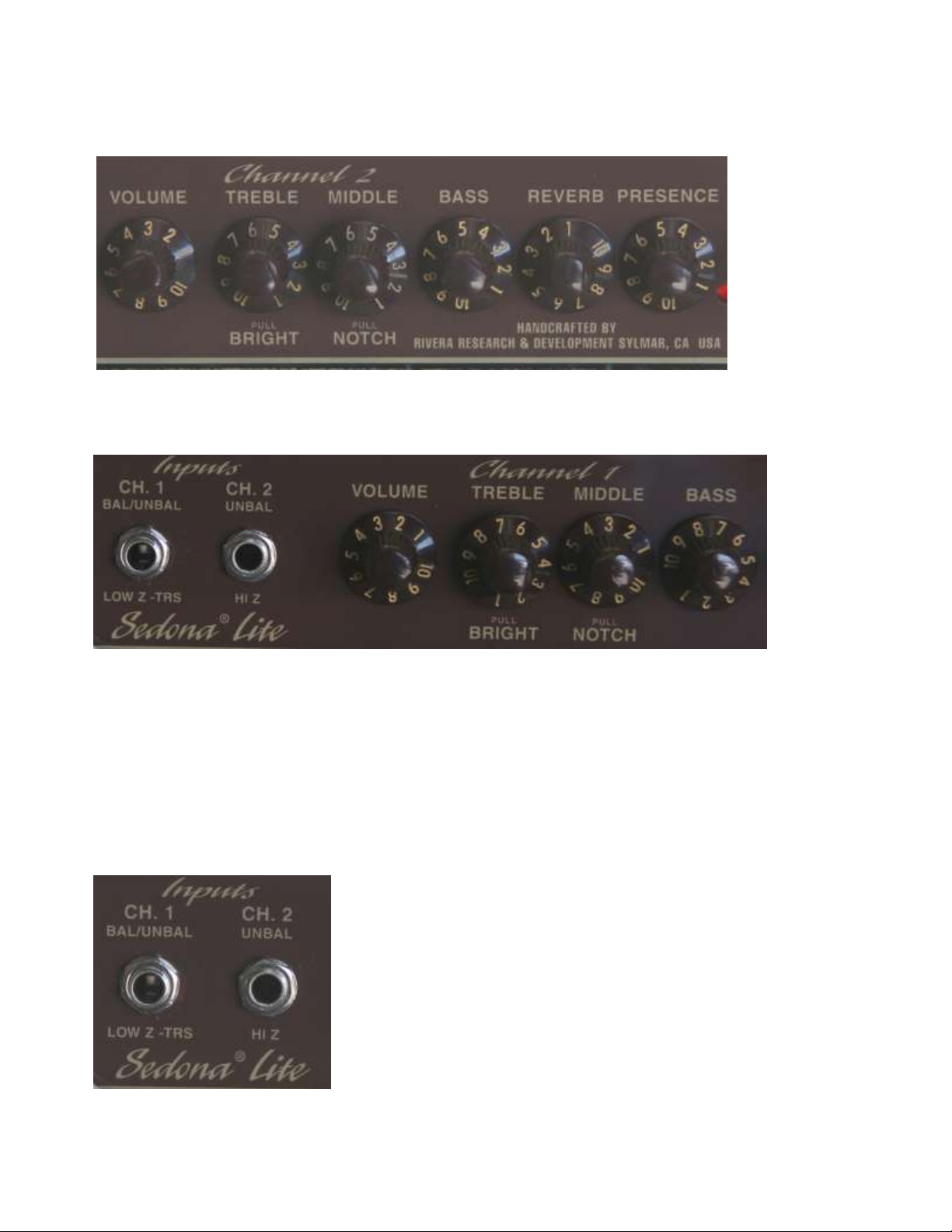
F R O N T PA N E L
Channel 1-Bal/Unbal input
This features a balanced or unbalanced input depending on the cable or instrument you use. If your
instrument has a balanced output like most Taylors with the Expression System, then you’ll want to
use a TRS to TRS cable (tip-ring-sleeve or also called stereo cable). You can also use Channel 1
for a Mic. Use a XLR to TRS cable when using a Mic. You can also use a non-balanced cable
when using a non-balanced instrument like most electric or acoustic guitars.
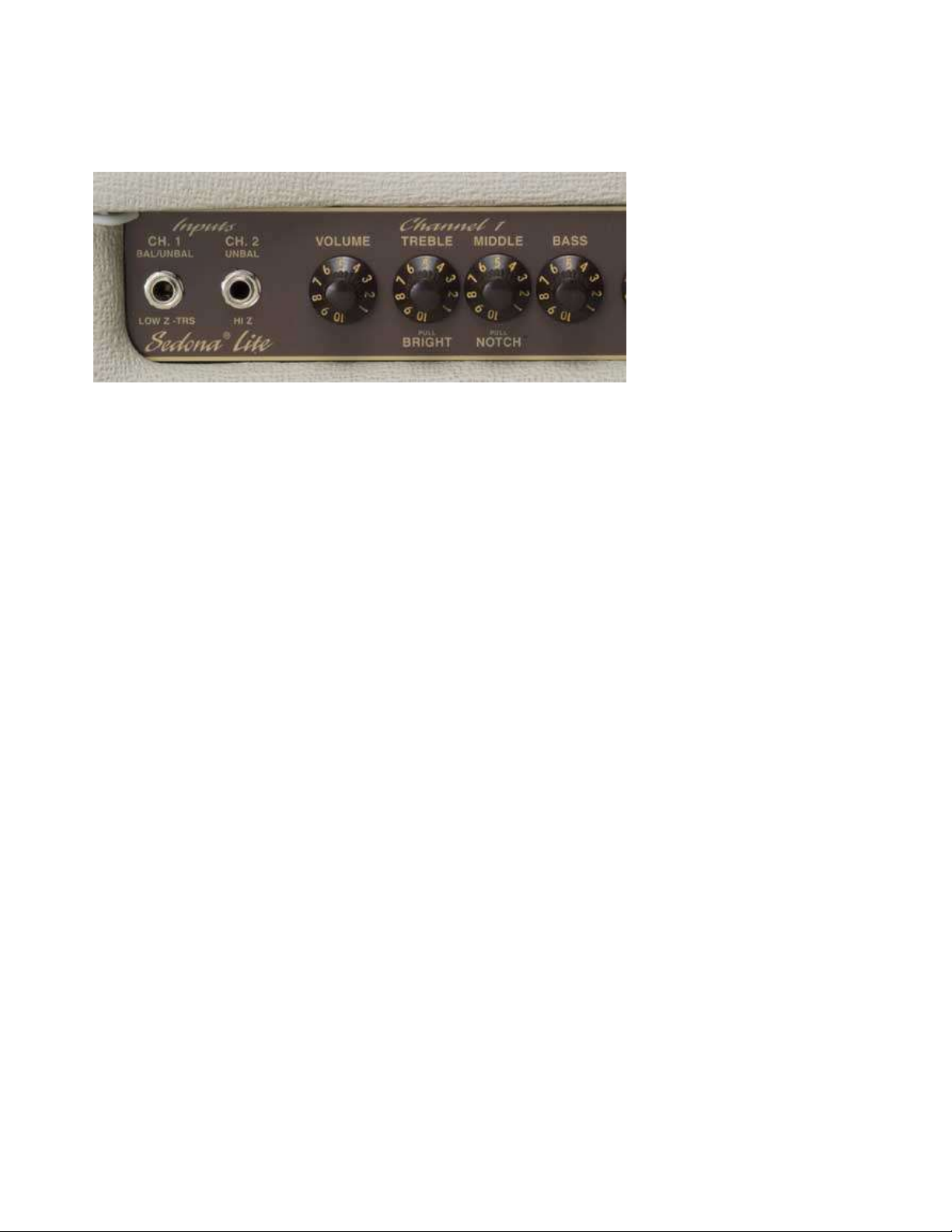
Channel 2-Unbal input
This is a normal non-balanced input for unbalanced instruments. Most electric and acoustic guitars
have a non-balanced output.
Channel 1
Channel 1 Both channels can be used simoultaneously. This can allows you to have separate
EQ for you Mic and your Guitar in Channel 2.
Channel 1 should be used for your Mic or Taylor ES-equipped guitars for maximum volume and
tone when balanced. You can also use Channel 1 with non-balanced guitars.
Volume
Although it’s labeled “Volume,” this control also adds gain. A simple rule of thumb is, the higher
the Volume is set, the more overdrive you’ll get.
Treble (with Pull Bright switch)
This treble control is similar in operation to the one on Channel 1. In addition, it has a built-in Pull
Bright switch. When pulled, it adds highlights to the tone. This is very useful for acoustic
instruments. If the treble frequencies are too extreme when the control is pulled, try setting the
treble control to a lower number and the Pull Bright switch off, and compare this tone to what you
get with the treble control at a higher setting. Note: Refer to the section on the Presence control for
an explanation of its relationship to adding brightness.
Middle (with Pull Notch switch)
The midrange circuit has a slight notch in the frequency spectrum at about 550 Hz, and turning the
knob alters that notch’s depth. Its Pull Notch switch shifts the notch’s frequency center down to
about 250 Hz. For reference, most 1950s “tweed” amps have their notch centered at 550 Hz, while
classic “blackface” amps have theirs centered at 250 Hz. Large-bodied acoustic instruments, such as
guitars and cellos, will have fewer feedback problems caused by resonant droning if the Pull Notch
switch is engaged.
Bass The “chunk” and support that form the backbone of your tone come from this control. Its
effect on your overall sound will be different at high and low volumes due to the speaker’s
characteristics and how much distortion you use.

Channel 2
Channel 2
Channel 2 has a non-balanced input. Use this channel for your non-balanced guitar.
Volume
Although it’s labeled “Volume,” this control also adds gain. A simple rule of thumb is, the higher
the Volume is set, the more overdrive you’ll get.
Treble (with Pull Bright switch)
This treble control is similar in operation to the one on Channel 1. In addition, it has a built-in Pull
Bright switch. When pulled, it adds highlights to the tone. This is very useful for acoustic
instruments. If the treble frequencies are too extreme when the control is pulled, try setting the
treble control to a lower number and the Pull Bright switch off, and compare this tone to what you
get with the treble control at a higher setting. Note: Refer to the section on the Presence control for
an explanation of its relationship to adding brightness.
Middle (with Pull Notch switch)
The midrange circuit has a slight notch in the frequency spectrum at about 550 Hz, and turning the
knob alters that notch’s depth. Its Pull Notch switch shifts the notch’s frequency center down to
about 250 Hz. For reference, most 1950s “tweed” amps have their notch centered at 550 Hz, while
classic “blackface” amps have theirs centered at 250 Hz. Large-bodied acoustic instruments, such as
guitars and cellos, will have fewer feedback problems caused by resonant droning if the Pull Notch
switch is engaged.
Bass The “chunk” and support that form the backbone of your tone come from this control. Its
effect on your overall sound will be different at high and low volumes due to the speaker’s
characteristics and how much distortion you use.
Reverb In the tradition of classic amps, your Sedona Lite is equipped with a spring reverb. Its
single-knob operation controls its effect on the signal coming from both
preamp channels. Specially buffered circuitry drives the reverb, keeping your tone intact
minimizing harshness.
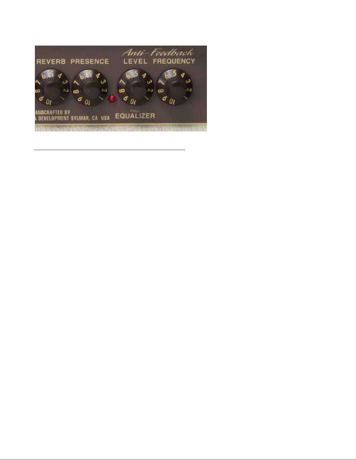
Presence The Presence control is incorporated as a vital part of the power amp section. Think of
it as a final brightness control after all the EQ, distortion, effects, and reverb.
Anti-Feedback Equalizer
This works with both channels simultaneously
The Sedona Lite is provided with a special circuit that can reduce the tendency or amount of
resonant feedback that commonly occurs when amplifying acoustic instruments. This is possible by
enabling a dip or cut in the frequencies that are amplified, with the frequency and amplitude of the
dip continuously variable (like a parametric equalizer). The design parameters of this “cut-only”
equalizer were chosen for their musical and sonic qualities.
It may also be desirable to use this feature for additional equalization to work in tandem with a
Channel’s passive 3-band (Treble, Middle, Bass) controls. For instruments that may have an
excessively fat or midrange tone, you can select a deeper midrange notch.
Anti-Feedback Level (with Pull On switch)
To activate this feature, pull out the knob on the control labeled Level located in the right area of
the front panel. An adjacent red LED will illuminate, indicating that the circuit is engaged. Rotating
this control adjusts the level of “cut,” or “dip,” with 1 providing the minimum cut and 10 providing
the maximum cut.
Anti-Feedback Frequency Control
Rotating this control with the Anti-Feedback equalizer engaged continuously sweeps the different
center frequencies of the “cut,” or “dip.” The knob setting of 1 corresponds to the narrowest range
(150 Hz) and 10 correspond to the widest range (3.5 kHz).
PRACTICAL USE OF THE ANTI-FEEDBACK EQUALIZER
A. For controlling feedback When the equalizer off, adjust the volume and tone
controls to taste. When a note or frequency begins to drone or howl, indicating feedback,
turn on the equalizer and rotate the Level knob to 10. Then rotate the Frequency knob until
you find the setting that tunes out the note or frequency that is feeding back. Now try
lowering the “cut” amount by decreasing the equalizer’s Level control until the feedback
comes back. Now slightly increase the amount of “cut.” By minimizing the Equalizer’s
“cut,” you minimize the effect it has on the overall tone. The most effective adjustment of
this equalizer is a matter of taste, and varies according to the type and size of your
instrument, Channel 1 or 2’s volume and tone settings, room acoustics, and your demands.
B. For additional EQ Some instruments require more midrange notch, or “cut,” than others,
so you may want to adjust your sound using the Anti-Feedback equalizer. For example, typical

rhythm accompaniment sounds are usually equalized for bottom and top-end tones with a decreased
midrange. Using an instrument with midrange-rich pickups such as dual-coil hum buckers may
require far more “cut” than a similar instrument equipped with single-coil pickups. Selecting a
humbucking pickup equipped semi-acoustic guitars neck-position pickup provides a very bass-
heavy and fat tone that may be too “dark,” but by experimenting with different settings, you can
dial in a much more pleasant rhythm sound.
Standby By turning the Power on and the Standby off (the down position, labeled with a
“0”), you can warm up the amplifier before applying full voltage to the preamp and power
output tubes. This prolongs tube life. Using the Standby switch when you’re taking a break
also helps to extend the tubes’ life, plus it keeps the amp constantly at the ready. Just flip the
Standby switch to the up (“I”) position, and you’re ready to play.
Power This is your main power switch. The on position is indicated by the light being
illuminated. The off position is marked by the “0” on the switch. Before turning the amp on, always
check that a speaker is connected and that the power cord is firmly plugged into the amp and the
outlet.
R E A R PA N E L
Mains Input
Your Sedona has a detachable power cord that connects to the chassis AC connector labeled Mains
Input. Always use this cord and, in the event that the power cord requires replacement, replace it
with the same type of power cord.
Consult your RIVERA dealer for further information. Be sure to use a grounded electrical mains
power supply socket whenever possible. These outlets have a grounding pin in addition to the
normal line and neutral pin. The power cord supplied with your Sedona has a 3-pin plug. Do not cut
off or damage the ground pin. If the available electrical outlet is of the older 2-pin type, use a
suitable ground-lift adapter. The U.S.A., Canada, and Japan share a common CSA/UL-style cord.
Most of Europe and Scandinavia utilize a Euro plug and have a NEMKO/CE-style cord. Australia
uses a different type of plug, as does England.
Note: Avoid using long extension cords. Long cords have sufficient resistance to electrical current
that the voltage arriving at your amp can be significantly reduced. This can have a bad effect on
your tone.
Mains Fuse
This AC line fuse protects your amplifier from damage due to shorts, momentary surges, and
defective power tubes. In the event of a fuse failure, always replace it with the same type of fuse.
Note: Always turn the amp off and wait about five minutes before replacing a fuse. This allows the
parts to cool and high voltages to dissipate.
For 100VAC and 115VAC versions, the Mains Fuse is: 3 Amp, 250 Volt Slo-Blo type (size 3AG,
or MDL)
For 230VAC versions, the Mains Fuse is: T 1.6A (time-delay, 5mm x 20mm size)
HT Fuse
The power amplifier circuit has its own fuse for protecting the output section from short circuits and
transient current peaks that exceed the normal current draw. These conditions are usually caused by
a bad tube. When a short circuit or transient peak causes the fuse to blow, the output tubes should
be checked and replaced, if necessary.
For 100VAC and 115VAC versions, the HT Fuse is: 1/2 Amp, 250 Volt Slo-Blo type (3AG, or
MDL)
For 230VAC versions, the HT Fuse is: T 500mA (time-delay, 5mm x 20mm size)
Repeated blowing of this fuse is a clear indicator of a defective output tube.
Always use the correct fuse value when replacing the HT Fuse.
If the Mains Fuse or the HT Fuse repeatedly blows, refer your amp to your local RIVERA dealer or
contact us at (818) 767-4600 or support@rivera.com for further service assistance.
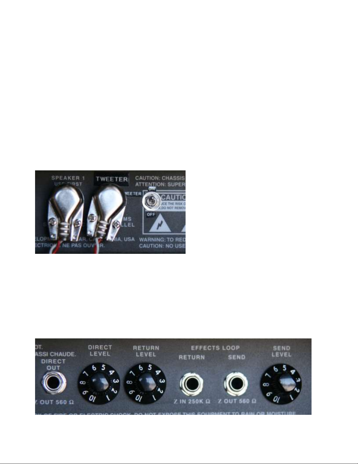
Speaker outputs
Two 1/4" Speaker Output phone jacks are provided. The first is for the Celestion G12T-75 full
range driver. The second is for the tweeter. The first jack of the pair labeled Speaker 1 must be
used first, as there is a built-in safety standby switch that will interrupt the power amp section from
drawing DC current if a plug is not inserted into the jack. (This feature is also provided for
technicians to easily and accurately adjust the amplifier’s bias by measuring the DC idle current.
See the Bias Adjustment section for more details.)
The second jack is intended to drive an internal tweeter or tweeter input of the Sedona Extension
Enclosure. The switch labeled Tweeter On/Off functions on this jack.
Effects Loop

Of course, you can use pedals and rack-mounted effects between your guitar and the amp. In fact,
that’s where most wah-wahs and other pedals sound exceptionally good. However, rack signal
processors are often best suited to being placed after the preamp’s tone-shaping circuitry. Your
Sedona’s Effects Loop is designed to give you the best match between the amp and the processor
by allowing you to set the level of the signal going to the effect, as well as the one coming back.
Therefore, you can tailor your amp/effects levels for best signal-to-noise ratio and the amount of
distortion you want. The Anti-Feedback Equalizer is placed in the signal chain after the Effects
Loop.
Note: The Effects Loop send can be used to route a signal to a guitar tuner.
The Effects Loop comes after the preamp and reverb sections. In addition, its low-impedance
circuitry lets you drive everything from the simplest stomp-box effect to the most sophisticated pro
signal processor with excellent results. It’s also fully buffered, meaning that it can drive long cords
and line-level gear and mixing consoles. (Because the signal is electrically unbalanced, you can use
an unbalanced-to-balanced output transformer to connect to equipment requiring a balanced input.)
Before you connect a signal processor to your amp, either turn the amp off or to standby.
Use high-quality shielded cords between the amp and processor. Never use a speaker cord.
Setting Effects Loop levels
1. After you connect the amp’s Send and Return with the signal processor’s input and output, set
the amp’s Send Level and Return Level between 1 and 2.
2. Plug in your guitar, turn the signal processor on, and then turn on the amp (or flip the standby
switch).
3. Set the amp’s Effects Loop Send Level and the signal processor’s input level so that you don’t
overload the processor. Keep your ears open for unwanted distortion from the signal processor
(you’ll know it by its crackly, unmusical sound). Whack a few chords on your guitar to check that
your settings are correct.
4. Now turn up the Effects Loop Return knob until the proper volume and overdrive are dialed in.
You’ll probably have to experiment with the signal processor’s output level until you get the best
sound and lowest amount of noise.
5. Make sure that you set your straight/effects blend at the signal processor, since all of your
preamp’s signal is passed through the Effects Loop. Do not use an effects-only output to return
from the processor to the amp. Always use the “mix” output, if the unit has one.
The Effects Loop Send is configured so that it is always active, so you can use it as a variable
output. Note that if you use the Send to drive slave amps, etc., and have nothing plugged into the
Return jack, the signal still passes from the preamp to the power amp.
Direct Out
Internal to Sedona is a direct box with an adjustable level output. It is terminated with an
unbalanced-line 3-pin XLR male-type connector, and can drive impedances as low as 600 ohms.
The signal-level output is continuously adjustable and can be set from below Instrument level
(-20dBv) to line level (+10dBv). This level is ultimately determined by the strength of the signal
from the instrument. Like any true direct box, the signal that is present at the ¼ output is directly
from the instrument, fully buffered.
Direct Level Control
To adjust the output of the Tube Direct Box, rotate the Level control until the desired level is
obtained. If you are connecting to a recording or broadcast-quality mixer, try bypassing the mixer’s
microphone preamp and plug in prefader. This may require increasing the level control’s setting,
but will save the noise generated by the microphone preamp in the mixer. It may also result in a
better overall sound quality.
Speaker System
Your Sedona’s speaker system has been specially designed to handle a wide variety of instruments
with the best possible tone. It is a two-way system, with a 12" JBL M121 driver and a special
Electro-Voice high-power dome tweeter. It has a crossover consisting of a 12dB/octave air-core
inductor divider network, with a crossover point at 4 kHz. To protect the driver and dome tweeter,
keep the grille on your amp at all times, do not expose the amp to moisture (direct or indirect), and
don’t use the back of your amp for storing any sharp objects.
1
C O N N E C T I N G T H E SEDONA WI T H OT H E R GE A R
Make sure the amp and all other gear are turned off whenever you make or change any connections.
Using a heavy-gauge speaker cord, connect the output jack labeled Speaker 1 with a Y cable and
reconnect the internal Jack and a the Speaker cord to the speaker input on an extension cabinet with
an 8-ohm impedance and power-handling capacity of at least 55 watts.
Don’t use a 16-ohm extension speaker.
Driving a full-range Sedona extension speaker cabinet
Using a Y cord, connect the Speaker 1 with the internal jack and speaker cable into the Full range
input of the Sedona extension cabinet. Then using a Y cord, connect the Tweeter output of the amp
with the internal Jack and speaker cable to the Tweeter input of the Sedona cxtension cabinet. This
will allow you to turn the tweeter on or off in both in the combo and the extension cabinet.
Note: Use only speaker cables.
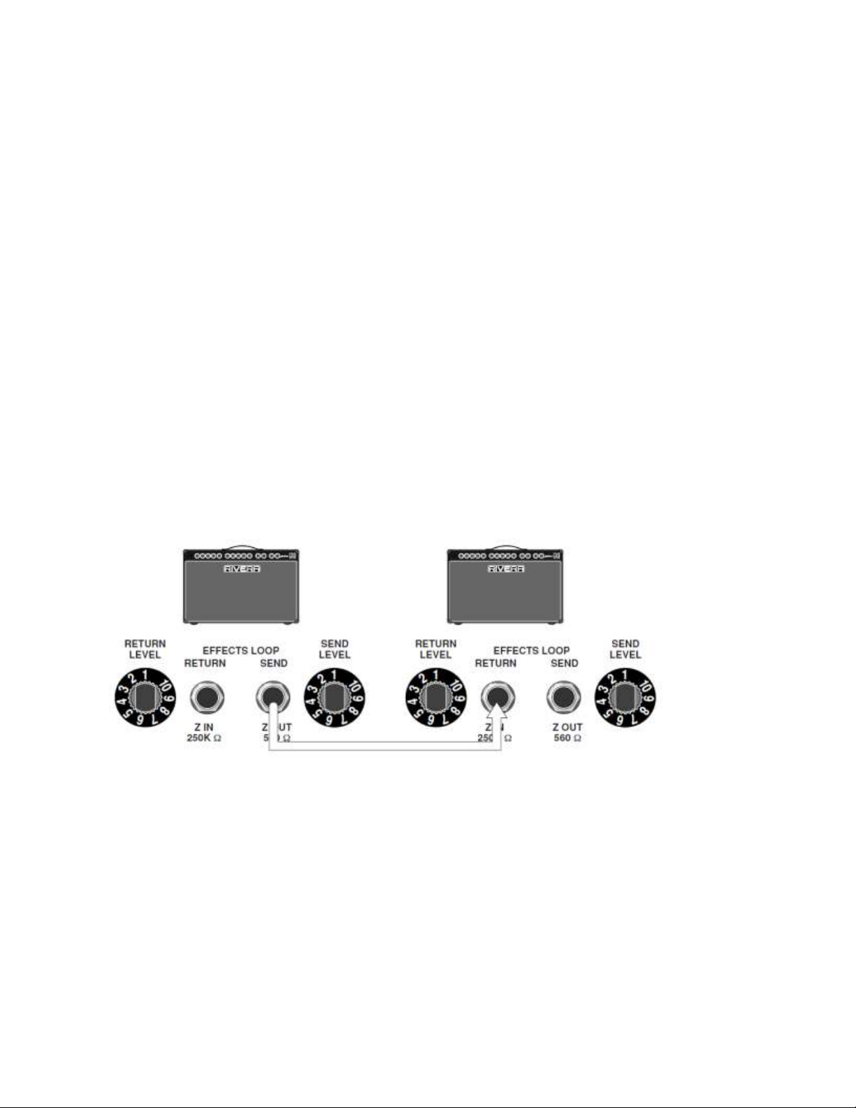
Slaving a second Sedona
Using a shielded cord, connect the first Sedona’s Effects Loop Send to the Effects Loop Return jack
on a second Sedona. Adjusting the Return Level sets the relative volume of the second amp. All
tone and distortion adjustments are made by the first amp. The first amp’s Send Level control sets
the signal level being sent to the second amp.

Slaving a second amp or power amp
5
Connect a shielded cord from your Sedona’s Effects Loop Send to the power amp input or Effects
Loop Return on a second amp. All volume and tone changes made on the Sedona will affect what
comes out of the second amp.
Caution: Never use the speaker outputs as line outputs. Their power level is extremely high and can
cause tremendous damage to another amp’s input. If you don’t have any effects patched into the
Sedona’s Effects Loop, you can use its Send jack instead of the Line Out. The Send Level knob
then acts as a variable output level.
987654321
__10987
654321
_
_10987654321
765432
1
Placing a signal processor in the effects loop
Using shielded cords, connect the Effects Loop Send to the processor’s input, and the processor’s
output to the Effects Loop Return. Adjust the mixture of effect/non-effect sounds at the signal
processor, and set the levels at the amp and processor for lowest distortion. If you use multiple
signal processors, connect them in series (processor 1’s output to processor 2’s input, etc.), and
patch the Sedona’s Send to the first processor’s input and the Sedona’s Return to the last

processor’s output. If the processor has stereo outputs, you can connect one to the Effects Loop
Return of a second amp.
Sending a direct signal to P.A. or recording gear
Using a shielded cord with an ¼ jack, connect the Sedona’s Direct Output to the line input or
channel input of a mixer. Caution: Never use the speaker output to connect to audio inputs.
654321
__10987654321
__1098
__10987654321
__10987
654321
_10987654321
Running two Sedonas in stereo
When you run two Sedonas in stereo, you can place a stereo signal processor (reverb, delay, etc.) in
the line between the first Sedona’s Effects Loop Send and the second Sedona’s Effects Loop
Return. Do not forget to include a return from the signal processor to the first Sedona’s Effects
Loop Return. Set the first Sedona’s Effects Send and Return levels and the signal processor's input
and output levels for best signal-to-noise ratio and best tone. In addition, set your effects/dry signal
blend in the signal processor. If you want to use a volume pedal, the line between the first Sedona’s
Effects Loop Send and the signal processor’s input is an excellent location. Always use high-quality
shielded cables for these connections.
C A R E & TR O U B L E S H O O T I N G
Chances are, you bought your RIVERA amp to make your guitar sound great, not to improve your
skills with electronics. What we’re saying is, “If something ever goes wrong with your amp, don’t
try to fix it yourself.” There are some potentially lethal high voltages inside the amp, plus if you do
something that causes even more damage than when you started out, the person who does the real

repair will probably tell you, “Hey, I know what’s wrong. Somebody’s been monkeying around in
here.” And, of course, your warranty will be void.
There are some things you can do to keep your amp running and to determine (and hopefully
remedy) common difficulties.
Keep the amp out of the elements. A lot of this is common sense. Don’t use your amp in
a sauna or in the bathtub. Don’t leave it out in the rain or in a damp basement. If you take it to a gig
or to practice and it’s cold out, give it 15 minutes or a half-hour to stand in the room where you’ll
be playing. That way, it can get acclimated and sound its best when you’re ready to play.
Be nice to it. The jury is still out on whether talking to plants makes them happy, or whether
Elvis lives on the moon, but the verdict on pampering amps is well-known. Don’t drop, knock over,
kick, or otherwise mistreat your amp. If you don’t have a flight case for travel, use the box it came
in, or wrap it in something thick, soft, and protective. RIVERA amps are built to take a lot, but why
push it? If you treat your amp well, it will treat you (and your guitar’s tone) well.
Check for loose tubes. Here’s as close as you should get to being inside your amp. With the
amp unplugged and cooled off, examine the tubes to make sure they’re in tight and straight. Note:
Unlike light bulbs, tubes push straight into their sockets. Never try to twist them! Also note that
some of the tubes are inside of metal sleeves. These are easy to remove for checking the tubes.
Grasp the sleeve with your fingers and depress it (it’s spring-loaded) and turn to the left
(counterclockwise). Now pull it off; this may require a little wiggling action. Remember to put the
sleeve back on after you check the tube.
Make sure the power cord is tightly plugged in. This is critical at both ends of the
cord. And don’t use one of those 3-pin-to-2-pin adapters unless you connect the ground lug to the
outlet. Leaving the ground disconnected isn’t just cheating—it’s dangerous to unground any
electrical device that’s supposed to be grounded.
Let it idle before you play. If you have a few minutes to spare before you play, turn the
amp on and set it to standby so that all the parts can get warmed up and stable. Once the amp’s nice
and warm (5 or 10minutes), flip the Standby switch and get busy on your guitar.
Don’t use the back of the cabinet as a storage locker. Remember, there’s a speaker
and glass tubes in there. Both cost money to replace (money that’s better spent on strings, picks,
etc., right?). Stash your footswitch and any other heavy and/or hard-edged stuff in a bag or a case
for travel.
Clean your amp once in a while. You can use a damp cloth or one dipped in a weak
solution of dishwashing detergent and water (lots of water!) to wipe off grime, dried Pepsi, and
whatever else accumulates on the vinyl covering. Make sure the amp is unplugged first. Everything
else can be vacuumed, as long as you’re gentle and use a soft-bristled brush attachment on the
vacuum hose.
1
QU I C K T R O U B L E S H O O T I N G GU I D E
Amp won’t turn on
1. Make sure that the AC mains cord is securely connected at both ends.
2. Verify the power source with something that you know works (a radio, a light, etc.).
3. Check the Mains Fuse, and replace it if necessary (if it blows again, refer your amp to qualified
service personnel).
There’s no sound
1. Make sure that the guitar cord to the input is okay (wiggle it—check your guitar’s volume
setting, too).
2. Check the Volume controls.

3. Check the Standby switch.
4. If an effect or signal processor is plugged into the Effects Loop, make sure it’s turned on and that
the level controls on the amp and processor are set correctly.
5. Check the speaker cable or cables to see if they are disconnected or shorted.
6. Check for blown speakers.
7. If a fuse is blown, replace it (if it blows again, refer your amp to qualified service personnel).
The amp shuts down unexpectedly
1. Follow the seven steps in the “There’s no sound” section.
2. Turn off the amp and wait 25 minutes before turning it on again. An internal thermal protection
circuit can shut the amp down if it becomes overheated.
3. After 25 minutes, turn it on, and if it shuts down again, refer the amp to qualified service
personnel.
Note: On SEMKO 230-volt models, there is one additional T 8A (250 Volt Slo-Blo type, 5mm x
20mm)
fuse and two T 1A (250 Volt Slo-Blo type, 5mm x 20mm) fuses located internally. These should
only be
replaced by qualified service personnel.
There’s unwanted distortion
1. Check the speaker.
2. Check the cables.
3. Check the signal level at other devices in the signal path.
4. One or more tubes may be bad (refer to the tube information on page 24, or take your amp to
qualified
service personnel).
B I A S AD J U S T M E N T
Caution! There are no user-serviceable parts inside your Sedona Amplifier.
The following information is intended for qualified technical personnel only. Do not remove
the Sedona Chassis from its cabinet, as high-voltage shock hazard exists inside this chassis.
Internal to the Sedona and located on the main PC board is a potentiometer for adjusting the bias.
The DC idle current can be measured between Pin 8 of the EL-34 tubes and the chassis ground. The
cathodes of the EL-34s are wired together and are switched by an isolated standby switch located in
the #1 speaker jack labeled “Speakers.”
Bias Test Procedure: Start by connecting a DC milliampere meter (most analog and digital volt
meters have this feature) between Pin 8 of the EL-34s and ground. With nothing plugged into
speaker jack #1, and an 8-ohm load connected into speaker jack #2, turn on the amplifier, and do
not insert a signal.
The DC Idle current should be set between 75 and 90 milliamperes for the pair of EL-34s.
Use a small screwdriver to turn the potentiometer on the main PC board, which raises or lowers the
idle current. If the tubes are set with excessive bias (low idle current), the sound will be gritty and
cold. If the idle current is set too high (low bias voltage), the EL-34 output tubes will run
excessively hot, and this will shorten their life considerably.
T U B E C A R E & R E P L A C E M E N T
Like a sports car, there’s a certain amount of wear and tear to be expected in a high-performance
tube amp. Over time, especially with hard use, tubes may need replacement. That’s why it’s a good
idea to make note of when you purchased your amp and whenever you replace tubes. It’s no
accident that your amp has two common types of tubes: They’re great-sounding and reliable, and
it’s easy to find replacements. Here’s a tube chart to show you which tubes go where.
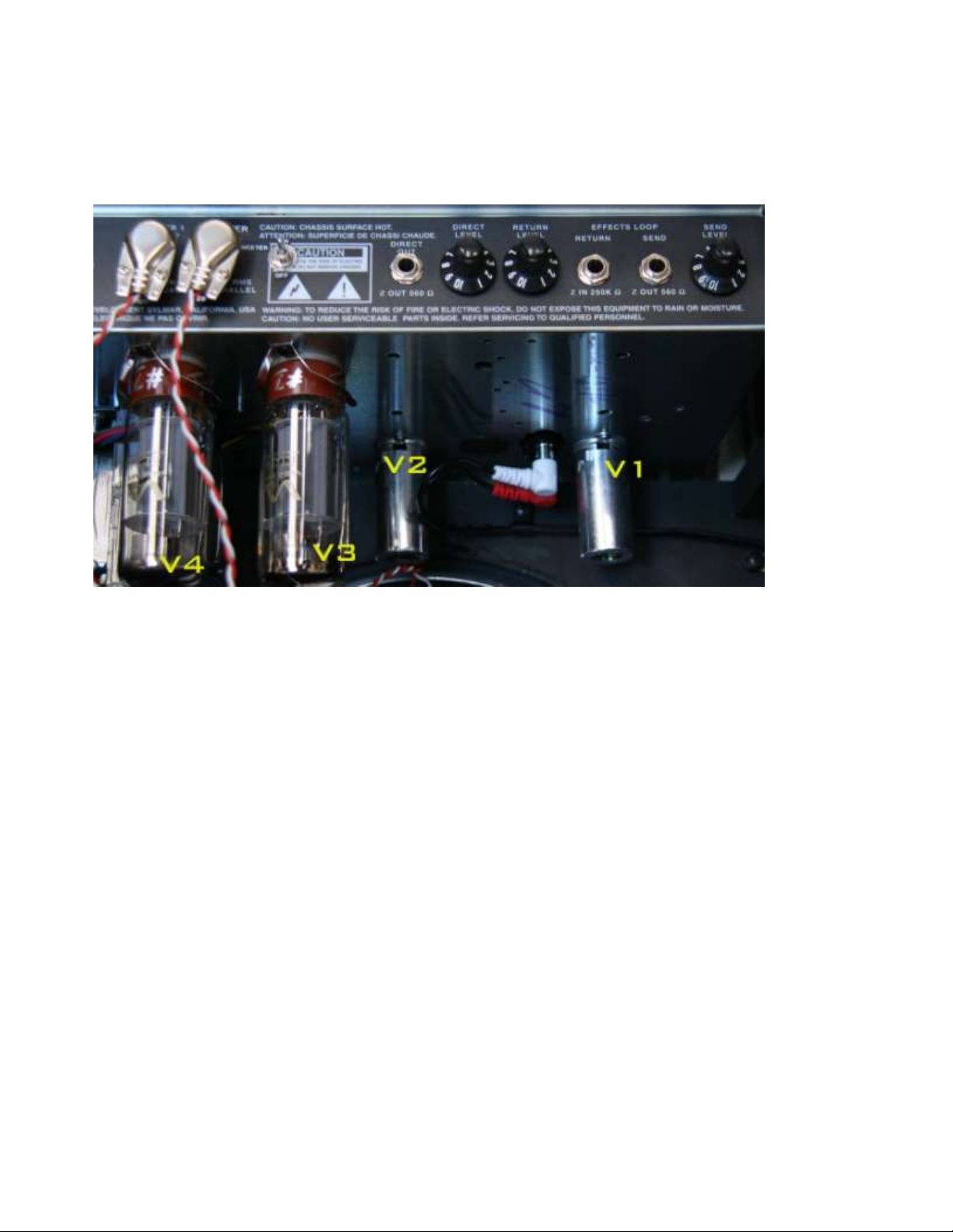
Location Type
Preamp tubes
V1 12AX7
V2 12AX7
Power Tubes
V3 EL-34
V4 EL-34
Here’s a brief description of what each tube does:
V1 Input buffer and tone control driver for Channel 1 & 2
V2 Phase inverter driver tube for the power amp section
V3 & V4 Power amp tubes—for best operation, they should always be changed in pairs
Checking for microphonic tubes
As tubes wear, some problems can come up. One of the most common symptoms is a ringing
sound. This is usually due to the tube becoming microphonic (like its name suggests, it’s picking up
sound and amplifying it).
With the amp unplugged and cooled off, examine the tubes to make sure they’re in tight and
straight. Never twist them! Gently grasp the tube and wiggle it into place. Because some of the
tubes are inside of metal sleeves, you will have to remove the sleeves to check them for
microphonics. Grasp the sleeve with your fingers and depress it (it’s spring-loaded) and turn to the
left (counterclockwise). Now pull it off; this may require a little wiggling action.
1
Preamp tube first aid
If you hear ringing (a feedback-like high-pitched sound) in your amp, it’s probably coming from a
preamp tube. The tube most susceptible to ringing are V1. Here’s a procedure to find which tube is
giving you trouble.
With nothing plugged into either the High Gain or Low Gain inputs, the amp on.
Turn up the Volume on Channel 1 and Channel 2. Now use the tip of a pencil to gently tap the end
of each of V1 and listen for sustained ringing or rattle.
Turn off the amp, and allow the tubes to cool. Now pull out the troublesome
tube and replace it with one of the same value (that is, if you’re
pulling out a 12AX7, replace it with a 12AX7).
Make sure that the tube is oriented correctly when pulling it out or putting it back in. If you look at
the end of the tube and the socket, you’ll notice that the nine pins are arranged in an incomplete
circle. Always make sure the pins are aligned correctly. Never force a tube into its socket.
Remember to put the sleeve back on after you check or replace a tube.
Power amp tube first aid
Like preamp tubes, power amp tubes can go bad or wear out. Your Sedona Lite has two power amp
tubes, and if one goes bad, they should both be replaced. This assures optimum output and tone.
If a power tube shorts out, the HT Fuse will be blown. Remove power from
the amp and replace the fuse before doing the following:
1. Remove the power tubes. Remember the way the eight pins are arranged, and note that the center
hole on the socket has a keyway that matches the center post on the tube.
2. Replace one tube. Turn the amp on again. If the fuse blows (or the tube glows cherry red,
indicating an internal short), you’ve found the bad tube. Turn off the amp immediately.
If the fuse doesn’t blow, replace the second tube and turn the amp on again.
3. When the tubes have cooled, remove them. Replace both tubes. (Don’t throw away the good tube
from the old pair, though—save it as a spare!)
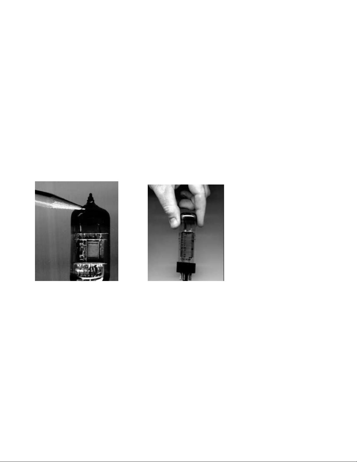
Testing a preamp tube: Tap gently
and listen for ringing. Grip the tube firmly and the wiggle it out of its socket.
Testing a preamp tube: Tap gently Grip the tube firmly and the
wiggle it out of its socket.
AC C E S S O R I E S
Available from your local Rivera dealer are accessories specifically designed for your Sedona
Amplifier.
Sedona Extension Enclosure: With the same speaker system as your Sedona Amplifier, this
handsome
extension enclosure features a closed back and a port, adding a substantial amount of level and
bottom
end when used in conjunction with the Sedona’s internal speaker system.
Rivera Replacement Tubes: All Rivera tubes are thoroughly tested and selected to assure that
your Rivera
Amplifier performs flawlessly through the years. Since our output tubes are graded and labeled, if
you

request the same grade of replacment as the original, you will not need to re-bias the amplifier
(provided
the bias was not adjusted from the original Rivera factory setting).
Footswitch Extension Cable: An optional 10-meter-long, 8-pin DIN male-to-female extension
cable is
available. Coupling the extension cable with the FS-7 footswitch’s 5-meter-long cable provides for
a 15-
meter total length. Up to two extensions may be used end to end between the Sedona and the FS-7.
S P E C I F I C AT I O N S
Speaker Output Impedance: 8 ohms
Direct Box Output Impedance: 600 ohms
Preamp Tubes: Two 12AX7A
Output Tubes: Two EL-34
Output Power: 55 Watts RMS into 8 ohms
Mains Operating Voltage: 115 Volts AC 50/60 Hz (North America), or 230VAC 50 Hz
(CE/Nemko model), 250 VAC 50 Hz (UK, Australia, New Zealand, and South Africa) or 100 VAC
50/60 Hz (Japan Only)
Speaker system: 12" Celestion G12T-75 8-ohm, high-power dome tweeter
Speaker System power handling: 75 Watts RMS
Crossover Network: 12 dB/octave air-core inductor
Crossover frequency: 4kHz
Reverb Type: Accutronics Spring
Height: 18"
Width: 20.75"
Depth: 12"
Weight: 49 lbs (estimate)
Cabinet Thickness: 3/4"
Baffle board: 3/4" Plywood
Covering: Nubtex
Cleaning of vinyl covering: Moist cloth, dishwashing liquid
Care of Grille cloth: Remove frame, use compressed air to blow out dust.
Because we strive to build the highest-quality product, we reserve the right to change specifications
of our products without prior notice.
Rivera Amplification
508 S. Varney, Burbank, CA 91502 USA
Phone: (818) 767-4600 • Fax: (818) 394-2097
Email: support@rivera.com • http://www.rivera.com
This manual suits for next models
2
Table of contents
Other Rivera Amplifier manuals


 Service manual")


