RIVETEC RL 6100 User manual

RIVETEC E120626
O P E R A T I N G M A N U A L
Pneumatic - hydraulic riveting tool with hexagonal holes
intended for mounting hexagonal riveting nuts
RIVETEC s.r.o., Albrechtice nad Vltavou 19, CZ - 398 16 Albrechtice nad Vltavou

OPERATING MANUAL
RL 6100
Page
2
Prepared by:
O. Čáp
RIVETEC E120626
TABLE OF CONTENTS
1.
TECHNICAL CHARACTERISTICS ..................................................................................................................... 3
2.
TOOL DESCRIPTION............................................................................................................................................. 4
2.1
P
REPARING BEFORE USE
...................................................................................................................................... 4
3.
OPERATION............................................................................................................................................................. 5
3.1
D
ESCRIPTION OF FUNCTIONS
............................................................................................................................... 5
3.2
P
UNCHING PROCESS
............................................................................................................................................ 7
3.3
P
UNCHING PINS CHANGING
................................................................................................................................. 9
4.
MAINTENANCE..................................................................................................................................................... 10
4.1
A
DDING HYDRAULIC OIL
,
VENTING OF THE HYDRAULIC
.................................................................................... 10
4.2
P
UNCHING SYSTEM CLEANING
.......................................................................................................................... 10

OPERATING MANUAL
RL 6100
Page
3
Prepared by:
O. Čáp
RIVETEC E120410
1. TECHNICAL CHARACTERISTICS
Pneumatic - hydraulic riveting tool with hexagonal holes intended for mounting hexagonal
riveting nuts
Range of application: - rivet nut holes for M4 - M8
- all types of material with a strength of 600 MPa (see Table 1)
- thickness from 0.5 to 6 mm (see Table 3)
Height: 300 mm
Length: 320 mm
Weight: 2,9 kg
Operating pressure: 6 Atm.
Tractive force at 6 atm.: 24.4 kN
Air consumption per hole: 7.0 l
Notice to the terms of use and safety when using the punchong tool
1. Prohibition of use the tool in explosive atmosphere
2. Compressed air used must conform to ISO 8573-1
3. Periodically check the hose connections with compressed air
Oil
The device is allowed to use only oils and lubricants recommended by the manufacturer
přístrojích je povoleno používat pouze oleje a maziva doporučená výrobcem
1. Hydraulic Oil ISO HN 32, e.g. OH-HM32
Noise and vibration
Acoustic noise level Lpai 86 db
Sound power level Lwai 103 db
(measured under ČSN ISO 3744:1996: ČSN EN ISO 12201:1997 )
total rms acceleration transmitted to the hands and % 0,5 m s
(measured under ISO/FDIS 8662-11:1999 )
OPERATING MANUAL
RL 6100
Page
4
Prepared by:
O. Čáp
RIVETEC E120626
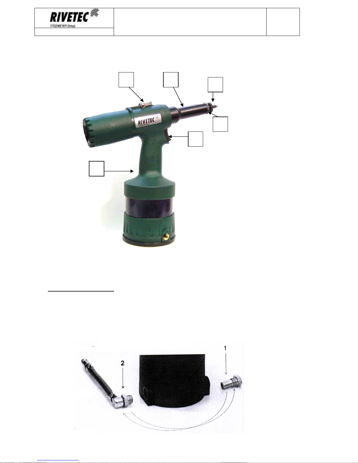
2. TOOL DESCRIPTION
Fig. 1
Max. working pressure of 7 bar. Compressed air as modified in accordance with ISO 8573-1.
Operating temperature + 5 °to + 45 °C.
2.1 Preparing before use
Remove the accessories from the safety valve (Fig. 2 Item 1) and air connection (Fig. 2 Item 2) and
screw of your choice for the right or left hand, one or the other side of the lower body of the device.
Safety valve wrench 17 and air connection internal hex key # 4 (You can use any air connection with
external thread R ¼ "with a nominal diameter of 6 mm according to ISO 228)
Fig. 2
1. Button
2. Punching trn
3. Nozzle
4. Front nozzle
5. Clamp
6. Oil filling screw
1
2
3
45
6

OPERATING MANUAL
RL 6100
Page
5
Prepared by:
O. Čáp
RIVETEC E120410
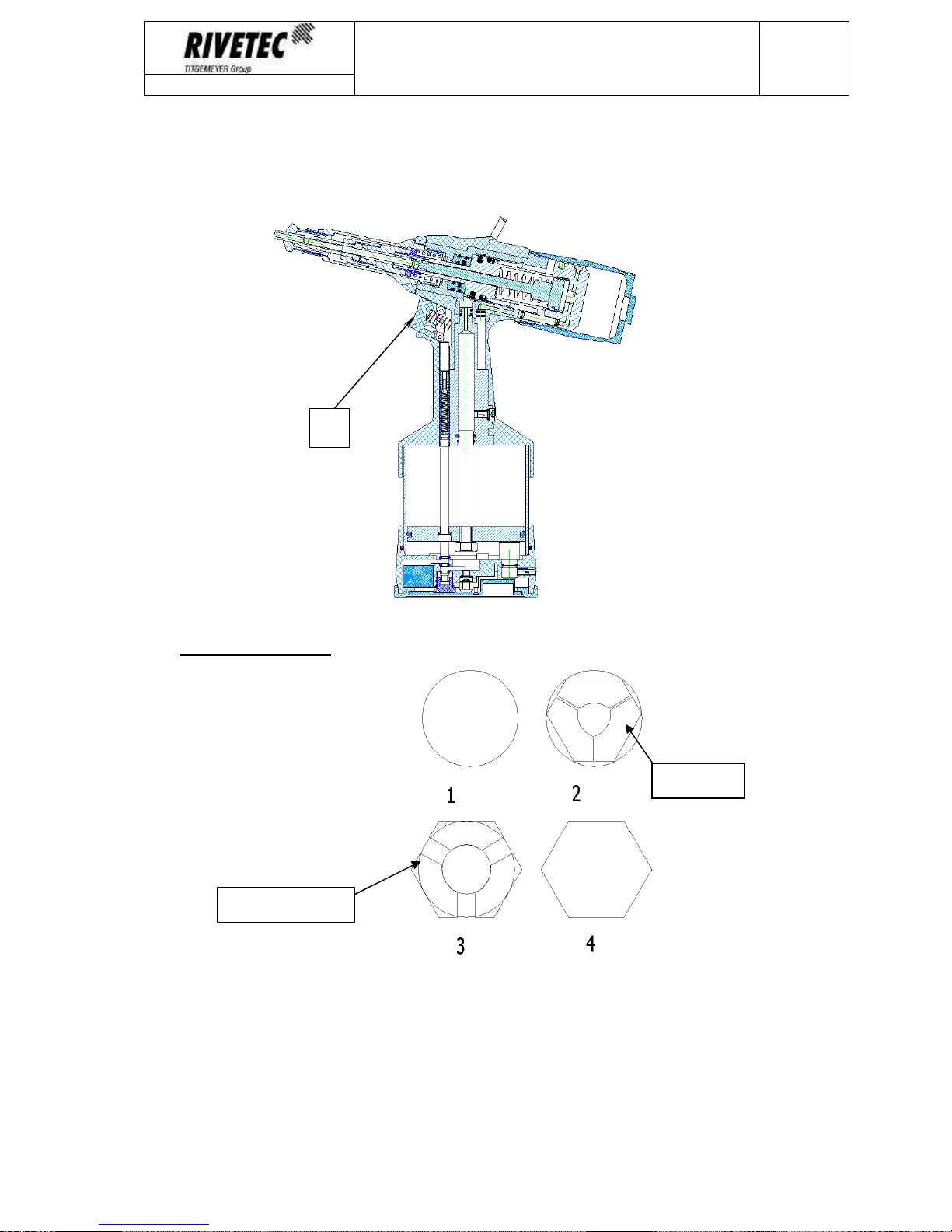
3. OPERATION
3.1 Description of functions
1
st
phase - tool is connected to compressed air, all internal components are on the starting
positions (punching thorn /1/ extends from the nozzle /2/, centering pin /3/ in the rear
position and does not interfere with a centering hole in the punching pin)
2
nd
phase – insert punching pin into the hole in the material
1
2
3

OPERATING MANUAL
RL 6100
Page
6
Prepared by:
O. Čáp
RIVETEC E120626
3
rd
phase - when button is pressed /4/ to the first position will open the ball valve /5/,
compressed air enters channels in the valve head /6/ and pushes the centering pin /3/ using
a pneumatic piston /7/ to punching pin /1/
4th phase – pressing the button /4/ to the end position of the main valve is open /8/ and
compressed air is released under the main pneumatic piston /9/, the piston in the cylinder is
pushed toward the hydraulic body /10/ and hydraulic rod /11/ pushes into the oil /12/, which
pushes hydraulic piston /13/ to the rear position. Given that the hydraulic piston /13/ strongly
associated with punching pin /1/, this also moves backwards and there is punching the
material between the punching pin /1/ and punchinch nozzle /2/.
4
5
6
7
8
9 10
11
12
13
OPERATING MANUAL
RL 6100
Page
7
Prepared by:
O. Čáp
RIVETEC E120410
5
th
phase – after releasing the button /4/ it will be back with the help of compression springs
to its original starting position
3.2 Punching process
1. The circular hole drilled in the plate
2. Insert the punching collet to the hole – that is pressed and skips to the edge of the
cylindrical part when placing next to the hole
3. Insert in the the center of the collet centering pin which expands punching collet into
the desired shape
4. After pulling the punching pin created a hexagonal hole
collet
Centering pin
4

OPERATING MANUAL
RL 6100
Page
8
Prepared by:
O. Čáp
RIVETEC E120626
Warning:
1. Always hold the tool perpendicular to punched material when punching.
2. Consider the size of the pre-drilled hole (this will ensure the centering pin ejection)
3. Before the next hole punching always remove chips from punching pin (prevent the damage)
Table 1
3.2.1.1 Punching pins and nose caps according to material thickness – ordering numbers
M4
M5
M6
M8
Drilled
hole
–
mm
(+0,1mm)
6,1
7,1
9,1
11,1
Punching set for material
up to 3mm 87-0001 87-0002 87-0003 87-0004
Punching set for material
from 3-6 mm - 87-0005 87-0006 87-0007
Punching
pin
for material
up to 3 mm 87-0450 87-0451 87-0453 87-0455
Punching
pin
fo
r material
from 3-6 mm - 87-0452 87-0454 87-0456
Table 2
3.2.1.2 Usability table ( according to material thickness in mm)
Material strength
(MPa) 100 200 300 400 500 600
Material thickness
(mm)
M8
steel
3,5 3,1 2,8 2,6
brass
4,1 3,7 3,5 3,2
Alloy (
Al)
4,6 4,2 3,9 3,7 3,5
M6
steel
4,1 3,5 3,2 2,9
brass
4,8 4,4 4,0 3,7
Alloy (Al)
5,5 5,0 4,6 4,3 4,0
M5
steel
5,0 4,3 3,9 3,5
brass
5,9 5,3 4,9 4,5
Alloy (Al)
6,0 6,0 5,6 5,2 4,9
M4
steel
5,8 5,0 4,5 4,0
brass
6,0 6,0 5,7 5,3
Alloy (Al)
6,0 6,0 6,0 6,0 5,7

OPERATING MANUAL
RL 6100
Page
9
Prepared by:
O. Čáp
RIVETEC E120410
3.3 Punching pins changing
Remove the front nozzle, allow the nut and remove the pin. We will exchange the pin, secure the nut
(pin must always be free to rotate). On the front nozzle mount the nose cap (appropriate size to
used pin) and secure by the locknut.
Punching pin
Centering
pin
Front nozzle Nose cap
locknut

OPERATING MANUAL
RL 6100
Page
10
Prepared by:
O. Čáp
RIVETEC E120626
4. MAINTENANCE
The user may only perform the activities described below, other maintenance and repair is
authorized to carry by the manufacturer or its authorized service centers.
4.1 Adding hydraulic oil, venting of the hydraulic
1. Disconnect the tool from any compressed air
2. Clamp the tool horizontally in a vice
3. Unscrew the filling oil screw by the internal hex key 4
4. Screw the filling adapter instead of screw
5. Fill the syringe with hydraulic oil and place it into the adapter
6. Add oil to the bottom visible thread rotation
7. Remove the syringe and remove the filling adapter
8. Give back the adding oil screw and tighten with internal hex key 4
9. Remove the tool from the vice and connect the compressed air supply
10. The tool is ready for use oplnění hydraulického oleje, odvzdušnění hydraulické části
4.2 Punching system cleaning
1. Keep the punching pin and nose cap cleen! To ensure the free movement of pin and
centering pin the chips must be removed during all the operation!
Manufacturer’s address:
RIVETEC spol. s r.o.
Tel.: +420 382 206 711
398 16 Albrechtice Nad Vltavou Fax: +420 382 206 719
Albrechtice Nad Vltavou 16 www.rivetec.eu
Czech Republic E-mail: info@rivetec.cz
Table of contents


