RIVI EV35 User manual

EV35 Access Point
Quick Setup Guide
This Quick Setup Guide provides step-by-step instructions on how to
field-install the EV35 access point (AP). For detailed information on
planning the installation, performing a site survey, and operating the
EV35.
WARNING! Only trained and qualified personnel should be allowed to
install, replace, or service this equipment.
WARNING! Installation of this equipment must comply with local and
national electrical codes.
CAUTION! Form a 80-mm to 130-mm (3-in. to 5-in.) drip loop in any
cable that is attached to the AP or the building. This will prevent water
from running along the cable and entering the AP or the building where
the cable terminates.
CAUTION! Be sure that grounding is available and that it meets local
and national electrical codes. For additional lightning protection,
use lightning rods and lightning arrestors.
CAUTION! Make sure that proper lightning surge protection
precautions are taken according to local electrical code.
CAUTION! RIVI strongly recommends that you wear eye
protection before mounting the EV35.
Required Hardware and Tools
•No. 2 Phillips screwdriver
•Small flat-blade screwdriver
•Wide flat-blade screwdriver
•Torque wrench or torque screwdriver with sockets
•Long-nose pliers
•Electrical wire stripping and terminal crimping pliers
•Pipe or pole, or a sturdy flat surface
•Electric drill with drill bits and customer-supplied wall anchors,
flat washers, and hex nuts for flat-surface mount
Package Contents
A complete EV35 field installation package includes all of the following
items:
•EV35 Access Point
•M25 data cable gland
•Ground wire with lug
•Pole/Wall Mount Bracket Kit
•Two steel pipe clamps
•Declaration of Conformity/Regulatory
Statement
FIGURE 1 EV35 Package Contents
1. EV35 Access Point
2. M25 data cable gland
3. Ground wire with lug
4. Pole/Wall Mount Bracket Kit
Unleashed Network Configuration
Setup Using the Unleashed Mobile App
To perform setup using the Unleashed Mobile App, download the iOS
or Android app from the app store.
Scan here for IOS app
3. Launch the app, and follow the on-screen instructions to configure
your Unleashed network(s).
FIGURE 2 Unleashed Mobile App for iOS and Android
FIGURE 3 Configuring Unleashed from the Mobile App
Setup Using a Web Browser
1. As soon as the Unleashed AP is powered on and connected to the
local network, it boots up and begins broadcasting a temporary
unencrypted WLAN named “Configure.Me-[xxxxxx]” from both
radios.
2. Using your client’s Wi-Fi connection settings, select and associate
to the “Configure.Me-[xxxxxx]” WLAN.
3. Launch a web browser and enter the following into the browser’s
URL bar: unleashed.rivinetworks.com, and press Enter.
4. You will be redirected to the Setup Wizard. Complete the steps in
the Setup Wizard and click Finish.
Page 1 of 4
© 2022 RIVI Networks Ltd. All rights reserved. Trade
Mark No: UK00003636458 Published Jan 2022,
Part Number 800-72972-301 Rev A
1. As soon as the Unleashed AP is powered on and connected to the
local network, it boots up and begins broadcasting a temporary
unencrypted WLAN named “Configure.Me-[xxxxxx]” from both
radios.
2. Using your client’s Wi-Fi connection settings, select and associate
to the “Configure.Me-[xxxxxx]” WLAN.
Scan here for Android app
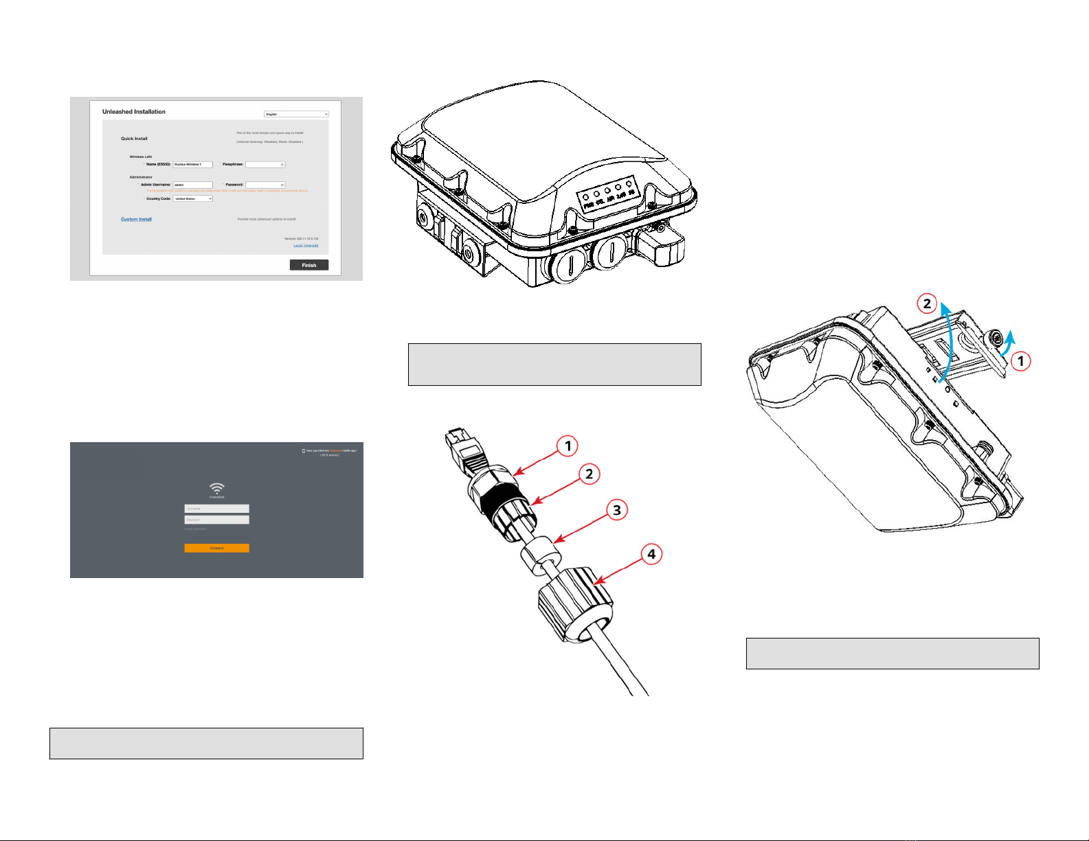
FIGURE 4 Complete the Setup Wizard to set up your
Unleashed network
5. Once the Setup Wizard is finished, a “Configuring system settings
and rebooting” progress screen appears. Wait until the process is
complete.
6. Connect to the WLAN that you configured in the Setup Wizard,
and click OK to reconnect. You will be redirected to the Unleashed
login screen.
7. Enter your Admin Name and Password to login.
FIGURE 5 The Login page
8. Upon successful login you will be presented with the Unleashed
Dashboard, which displays an overview of your Unleashed
network.
Mounting Instructions
Connecting and Sealing the RJ-45 Cables
Connect and seal the RJ-45 cables using the M25 data cable glands.
WARNING! Do not use any PoE injector not tested and approved by
RIVI to power the EV35 Access Point.
FIGURE 6 EV35 LEDs and Ports
1. Feed the end of the cable through the sealing nut, rubber O-ring,
clamping ring assembly, and cable gland base, as shown in Figure 7.
NOTE: Do not seat the clamping ring and rubber O-ring into
the gland body until the gland body has been torqued to
specifications.
FIGURE 7 RJ-45 Cable and Gland Assembly
1. Cable gland
base
2. Clamping ring
3. Rubber O-
ring
4. Sealing nut
2. Use a wide flat-blade screwdriver to remove the required (PoE IN)
blanking cap from the AP.
3. Connect the cable to the Ethernet port on the AP.
4. Tighten the cable gland base into the AP chassis to 7 N.m or 62 in-
lbs.
5. Wrap the clamping ring assembly around the rubber O-ring. Make
sure that the clamping ring assembly fully encloses the rubber O-
ring.
6. Seat the clamping ring assembly and rubber O-ring in the cable
gland base.
7. Hand-tighten the sealing nut.
Attaching the Mounting Bracket to a Flat Surface
1. The AP mounting bracket attaches to the AP using a captive screw.
Use a medium flat-blade or No. 2 Phillips screwdriver to loosen
the captive screw, as shown in Figure 8, and pull up on the end
of the bracket to remove the bracket from the AP, as shown in
Figure 8.
FIGURE 8 Removing the Mounting Bracket
1. Loosen the captive
screw
2. Pull up on the end of the
bracket
2. Using either of the two options shown in Figure 9, hold the mounting
bracket at the location on the mounting surface where you want
to mount the AP. Use the holes on the mounting bracket as a
template to mark the locations of the mounting holes.
NOTE: The mounting bracket can be mounted to a vertical or
horizontal surface to support the AP in the required orientation.
Page 2 of 4
© 2022 RIVI Networks Ltd. All rights reserved. Trade
Mark No: UK00003636458 Published Jan 2022,
Part Number 800-72972-301 Rev A
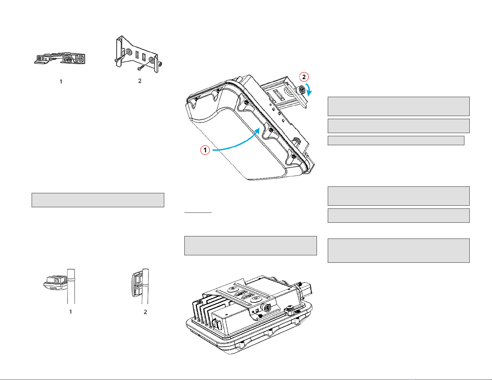
FIGURE 9 Mounting Bracket on a Flat Surface
1. Horizontal mounting 2. Vertical mounting
3. Remove the mounting bracket from the mounting surface.
4.
5.
Drill holes required for the customer-supplied mounting
hardware. Attach the mounting bracket to the flat surface using
the mounting hardware.
6. Using the mounting hardware instructions, tighten the
hardware to secure the mounting bracket.
7. Continue with Mounting the AP on page 3.
Attaching the Mounting Bracket to a Pole
1.
2.
The AP mounting bracket attaches to the AP using a captive
screw. Loosen the screw and pull up on the end of the bracket to
remove the bracket from the AP, as shown in Figure 8 on page 2.
Insert the open end of one steel clamp into two of the slots on the
mounting bracket.
NOTE: The mounting bracket can be mounted to a vertical or
horizontal pole to support the AP in the required orientation.
3.
4.
Using either of the two options shown in Figure 10, use the clamps
to attach the mounting bracket to the pole. Tighten the clamps to
3 N.m or 27 in-lbs, or per manufacturer’s specifications if the
factory-supplied clamps are not used.
If necessary, daisy-chain the other steel clamps to accommodate
larger poles.
FIGURE 10 Mounting Bracket on a Pole
1. Horizontal pole
mounting
2. Vertical pole mounting
5. Continue with Mounting the AP.
Mounting the AP
1. Snap the AP back onto the mounting bracket, as shown in Figure 11,
and use a medium flat-blade or No. 2 Phillips screwdriver to
tighten the captive screw to 1.1 N.m or 10 in-lbs to secure the
bracket to the AP, as shown in Figure 11.
FIGURE 11 Attaching the Mounting Bracket to the AP
1. Snap the AP to the
mounting bracket
2. Tighten the captive
screw
2. Optional Step: If you also need to lock the mounting bracket to the
AP, then use an appropriately sized screwdriver to screw the
customer-supplied locking stainless steel 6-mm M3 panhead
security screw through the mounting bracket and into the AP
chassis.
CAUTION! Make sure that the customer-supplied locking stainless
steel M3 panhead security screw is no longer than 6mm. If the
security screw is longer than 6mm, it can damage the AP chassis.
FIGURE 12 Locking the Mounting Bracket to the AP
You have completed mounting the AP to the mounting bracket.
Powering the AP with DC Power
The AP can accommodate two sources of power: PoE (48V) power and
12V DC.
The AP can draw power from the Ethernet input as a Class 4 device,
providing a maximum of 18 W to the system. Alternately, power can be
supplied through a customer-provided 12V DC power supply (12V DC
preferred, 7-20V DC acceptable) that will connect to a two-pin terminal
block. The terminal block is accessible through a water-tight gland on
one end of the unit. The terminal block connection has surge and
polarity protection to protect against inserting the wrong polarity leads
into the terminal block.
NOTE: If both the PoE and DC ports are used, separate cable glands
must be used for each port. Additional cable gland (Part Number
902-0183-0000) can be be purchased.
NOTE: When both the 12V DC and the 48V PoE power are active, the AP
will prioritize the 12V DC power.
CAUTION! Ensure that the DC power source does not exceed 20V DC.
1. Install the DC power supply as described in the DC power
supply accessory installation guide.
2. Connect the power cord to a DC power source.
3. Verify that the PWR LED is a steady green.
Earth Grounding the AP
CAUTION! Make sure that earth grounding is available and that it meets
local and national electrical codes. For additional lightning protection,
use lightning rods and lightning arrestors.
NOTE: The color coding of ground wires varies by region. Before
completing this step, check your local wiring standards for guidance.
Using the factory-supplied ground wire and ground screw and washer
set, connect a good earth ground to the AP chassis ground point.
CAUTION! The EV35 includes one 9-mm stainless steel M6x1 earth
ground screw with split lock and flat washers. Make sure that any
replacement screw is no longer than 9 mm. If a screw is longer than 9
mm, it can damage the AP chassis.
Page 3 of 4
© 2022 RIVI Networks Ltd. All rights reserved. Trade
Mark No: UK00003636458 Published Jan 2022,
Part Number 800-72972-301 Rev A

FIGURE 13 Connecting a Good Earth Ground to the AP
1. Earth ground screw
Installing a USB Dongle
To install a USB dongle (for example, an IoT radio device such as BLE,
802.15.4, Z-wave, or similar), remove the two 3-mm hex screws,
remove the cap, and insert the dongle into the USB port.
Once installed, replace the cap and the hex screws, and tighten the
screws to 0.79 N.m or 7 in-lbs.
NOTE: If required, a larger USB dongle cap can be purchased
separately. The maximum dimensions of the USB dongle that can be
inserted (with the large USB dongle cap, part # 902-0127-000) are 6
cm x 2 cm x 1.1 cm. Max Power: 450mW (SiLabs EM3578 max current
draw at +20 dBm is 80mA over a 3.3V rail).
FIGURE 14 Installing a USB Dongle
Troubleshooting
CAUTION! If required, you can reset the AP to its factory default
settings by pressing the reset button located inside the PoE IN port.
Use the tip of a pen or a 3-mm flat-blade screwdriver to press the reset
button. Press and hold the reset button for 4 seconds or longer to
restore to factory defaults. DO NOT RESET THE AP TO FACTORY
DEFAULT SETTINGS UNLESS SO INSTRUCTED. (Doing this resets the
AP IP address to 192.168.0.1.)
NOTE: After a reset, you can access the internal AP web interface
using https://192.168.0.1. Your device must use any other address
from 192.168.0.2 through 192.168.0.254, with subnet mask
255.255.255.0. The username is super, and the password is sp-admin.
Refer to the Outdoor Access Point User Guide for information on
configuring and operating the AP. This document is available at
https://support.rivinetworks.com.
Page 4 of 4
© 2022 RIVI Networks Ltd. All rights reserved. Trade
Mark No: UK00003636458 Published Jan 2022,
Part Number 800-72972-301 Rev A
Other RIVI Wireless Access Point manuals


 installation guide")
