RKR Designs LLC Alpha 8410 User manual

Alpha 8410 Linear Amplifier
User Manual
RKR Designs LLC
Document Issue 1.1
August 2015

Alpha 8410 Linear Amplifier User Manual RKR Designs LLC
DOCNUMBER 8410
Document Issue 1.1
Page ii August 2015
Alpha 8410 Linear Amplifier User Manual
RKR Designs LLC
632 S Sunset St
Longmont CO 80501
303-473-9232
To reach technical support or obtain copies of this document, go to
www.rksdesignsllc.com.
Copyright © 2014 RKR Designs LLC. All rights reserved. Specifications
subject to change without notice.

RKR Designs LLC
Product Release 1 Contents
DOCNUMBER 8410
Document Issue 1.1
August 2015 Page iii
Contents
1. Introduction . . . . . . . . . . . . . . . . . . . . . . . . . . . . . . . . . . . . 1-1
1.1 Product Description 1-1
1.2 Product Capabilities 1-2
1.3 Safety Considerations 1-2
1.4 Related Products 1-3
1.5 Assistance 1-4
2. Amplifier Components and Specifications . . . . . . . . . . . . . . . . . . . 2-1
2.1 Boards 2-3
2.2 Controls and Display 2-6
2.3 Output-Tank Circuit 2-6
2.4 Tubes and Tube Deck 2-6
2.5 Specifications 2-7
3. Preparing Your Station . . . . . . . . . . . . . . . . . . . . . . . . . . . . . . 3-1
3.1 Prepare Your Station 3-1
3.2 Limitations of Operation at Nonstandard Voltage 3-4
4. Setting Up the Amplifier . . . . . . . . . . . . . . . . . . . . . . . . . . . . . 4-1
4.1 Unpack the Amplifier and Transformer 4-1
4.2 Connect the Transformer 4-2
4.3 Check the Tubes and Exhaust Chimney 4-3
4.4 Connect the Voltage Tap 4-3
4.5 Connect the Cables 4-4
4.6 Set the Input-Drive Power 4-6
4.7 Connect the Transceiver Keying Line 4-7
5. Operating the Amplifier . . . . . . . . . . . . . . . . . . . . . . . . . . . . . . 5-1
5.1 Principles of Operation 5-1
5.2 Start Up the Amplifier 5-2
5.3 Tune the Amplifier 5-3
5.4 Operate the Amplifier 5-7
6. Maintaining the Amplifier . . . . . . . . . . . . . . . . . . . . . . . . . . . . . 6-1
6.1 Clean the Amplifier Chassis 6-1
6.2 Replace Tubes and/or Fuses 6-2
6.3 Retune the Amplifier 6-3
7. Diagnosing Faults and Troubleshooting . . . . . . . . . . . . . . . . . . . . 7-1
7.1 Diagnose Faults 7-1
7.2 Troubleshoot Problems 7-4
Terminology Term-1
Schematics Schem-1

Alpha 8410 Linear Amplifier User Manual RKR Designs LLC
Contents Product Release 1
DOCNUMBER 8410
Document Issue 1.1
Page iv August 2015

List of Procedures
DOCNUMBER 8410
Document Issue 1.1
August 2015 Page v
List of Procedures
Procedure 3-1, “Prepare your station,” page 3–1
Procedure 4-1, “Unpack the amplifier and transformer,” page 4–1
Procedure 4-2, “Connect the transformer,” page 4–2
Procedure 4-3, “Check the tubes and the exhaust chimney,” page 4–3
Procedure 4-4, “Connect the voltage tap,” page 4–4
Procedure 4-5, “Connect the cables,” page 4–4
Procedure 4-6, “Connect the transceiver keying line,” page 4–7
Procedure 5-1, “Start up the amplifier,” page 5–2
Procedure 5-2, “Tune by the recommended dip-and-load method,”
page 5–5
Procedure 5-3, “Tune by the alternate nominal-gain method,” page 5–5
Procedure 5-4, “Operate the amplifier,” page 5–7
Procedure 6-1, “Clean the amplifier chassis,” page 6–1
Procedure 6-2, “Replace tubes and/or fuses,” page 6–2

Alpha 8410 Linear Amplifier User Manual RKR Designs LLC
List of Procedures
DOCNUMBER 8410
Document Issue 1.1
Page vi August 2015
1
DOCNUMBER 8410
Document Issue 1.1
August 2015 Page 1–1
1 Introduction
1.1 Product Description 1–1
1.2 Product Capabilities 1–2
1.3 Safety Considerations 1–2
1.4 Related Products 1–3
1.5 Assistance 1–4
Congratulations on your purchase of a professional-quality Alpha 8410
linear amplifier.
1.1 Product Description
The Alpha 8410 (see Figure 1-1) is a self-contained manual-tune HF
linear power amplifier. It is capable of continuous operation at 1500 W
peak power output on single sideband (SSB), keyed continuous wave
(CW), slow-scan television (SSTV), radioteletype (RTTY), digital modes
or FM, with no time limit.
CAUTION
!
CAUTION! Study this manual carefully before operating your
amplifier for the first time. In particular, it is extremely important that
you thoroughly review the installation and operation sections. Failure
to do so could result in serious damage not covered under warranty.
Remember
REMEMBER Amplifier components as photographed for this manual may differ
from those in your amplifier, depending on your amplifier vintage.

Alpha 8410 Linear Amplifier User Manual RKR Designs LLC
Introduction
DOCNUMBER 8410
Document Issue 1.1
Page 1–2 August 2015
11
1
Figure 1-1 Alpha 8410
1.2 Product Capabilities
Product capabilities include:
•Continuous RF output. The Alpha 8410 is capable of 1.5-kW
continuous RF output on all commonly used modes and on any
authorized amateur frequency from 1.8 to 29.7 MHz (other than the
60-meter band).
•Compatibility with popular amateur transceivers and exciters. The
Alpha 8410 requires ~50-W peak RF drive for 1.5-kW output.
•Capable of full CW break-in (QSK) and all digital modes when used
with any appropriate transceiver.
•Built-in protective functions. The control system incorporates
protective functions that minimize the probability of accidental
damage to the amplifier or its power tubes. In most cases, when one
of the protective functions is tripped, the amplifier goes to standby.
•USB interface allows for remote operations, diagnostics, and
firmware upgrades.
1.3 Safety Considerations
•Locate the Alpha 8410 where there is good air circulation all around
and on top of the cabinet. The unit may become hot during operation.
•When moving the Alpha 8410, use proper lifting techniques and two
people. Never transport the amplifier with the transformer in place.

1
1
1
DOCNUMBER 8410
Document Issue 1.1
August 2015 Page 1–3
RKR Designs LLC Alpha 8410 Linear Amplifier User Manual
Introduction
•Although the Alpha 8410 meets international safety standards and
FCC regulations, remember that the equipment works with high
voltages that can be LETHAL!
This operating manual contains information, cautions, and warnings that
you must follow to ensure safe installation and operation. Read Chapter 1
before attempting to unpack or operate the Alpha 8410. Failure to perform
procedures properly may result in amplifier damage, fire hazard, or
electric shock.
!
IMPORTANT •NEVER open the amplifier case without unplugging the unit
from the wall outlet.
•NEVER touch an antenna during transmission.
•NEVER turn on the amplifier without the cover securely in
place and all attachment screws inserted.
•NEVER turn on the amplifier without a good ground
connection on the rear-panel ground terminal.
•NEVER turn the amplifier back on after a hard fault (that is, a
fault to power off) without waiting at least 20 seconds.
•NEVER cover or obscure the exhaust holes in the amplifier
cover. Never stick objects into the holes or allow liquids to
enter through the holes.
•NEVER allow key-down plate current to exceed 1.5 A for
more than 1 or 2 seconds. If you do and a plate current trip
occurs, it automatically resets in ~4 seconds if the amplifier
is returned to receive (key-up).
•NEVER allow the red GRID LED to stay brightly illuminated
for more than 1 second.
1.4 Related Products
Other products available to enhance your use of the Alpha 8410 include:
•Alpha 2000 full 1500-W-rated 50-ohm dummy loads
•Alpha 4500 series standing-wave-ratio (SWR) meters and wattmeters
For more information, go to www.rksdesignsllc.com or call 303-473-
9232.

Alpha 8410 Linear Amplifier User Manual RKR Designs LLC
Introduction
DOCNUMBER 8410
Document Issue 1.1
Page 1–4 August 2015
11
1
1.5 Assistance
Technical assistance from RKR Designs is available from several
sources.
•Go to our website at www.rksdesignsllc.com and click Support. On
this site you can get the following assistance:
•Alpha Forum
•FAQs
•Legacy equipment information
•Manuals
•Repair information
•Software downloads
•Tech tips
•Technical support
•E-mail us by completing a support request at
www.rksdesignsllc.com.
•Fax us at 719-428-1919.
•Phone us at 303-473-9232.

2
DOCNUMBER 8410
Document Issue 1.1
August 2015 Page 2–1
2 Amplifier Components and Specifications
2.1 Boards 2–3
2.2 Controls and Display 2–6
2.3 Output-Tank Circuit 2–6
2.4 Tubes and Tube Deck 2–6
2.5 Specifications 2–7
Remember
REMEMBER Amplifier components as photographed for this manual may differ
from those in your amplifier, depending on your amplifier vintage.
The Alpha 8410 uses ceramic-and-metal forced-air-cooled tetrode
vacuum tubes for amplification. The main power supplyis an unregulated
transformer/rectifier/capacitor power supply for the high-voltage (HV)
and heater circuits. All other power supplies are regulated.
The control circuit uses a microprocessor “in the loop” to monitor and
control amplifier operation. There are seven circuit boards in the
amplifier:
•Center-partition board
•Control board
•Display board
•HV board
•Mains board
•Transmit/receive (T/R) board
•Tube-deck board
In addition to these, the tubes, tank circuit assembly, and transformer
complete the main sections of the amplifier. These major blocks are
described below.
The amplifier includes a 5-V power supply mounted behind the front
panel. Whenever the amplifier is plugged into the mains power, this
supply is active and there is power to the microcontroller on the main
control board. This feature enables the amplifier to be turned on or off
remotely. It also enables remote monitoring and debugging via a USB
cable connected to a computer.

Alpha 8410 Linear Amplifier User Manual RKR Designs LLC
Amplifier Components and Specifications
DOCNUMBER 8410
Document Issue 1.1
Page 2–2 August 2015
22
2
The amplifier front, back, and interior are shown below (see Figure 2-1,
Figure 2-2, and Figure 2-3). Amplifier components are listed
alphabetically and described below.
Figure 2-1 Amplifier front
Figure 2-2 Amplifier back
2
2
2
DOCNUMBER 8410
Document Issue 1.1
August 2015 Page 2–3
RKR Designs LLC Alpha 8410 Linear Amplifier User Manual
Amplifier Components and Specifications
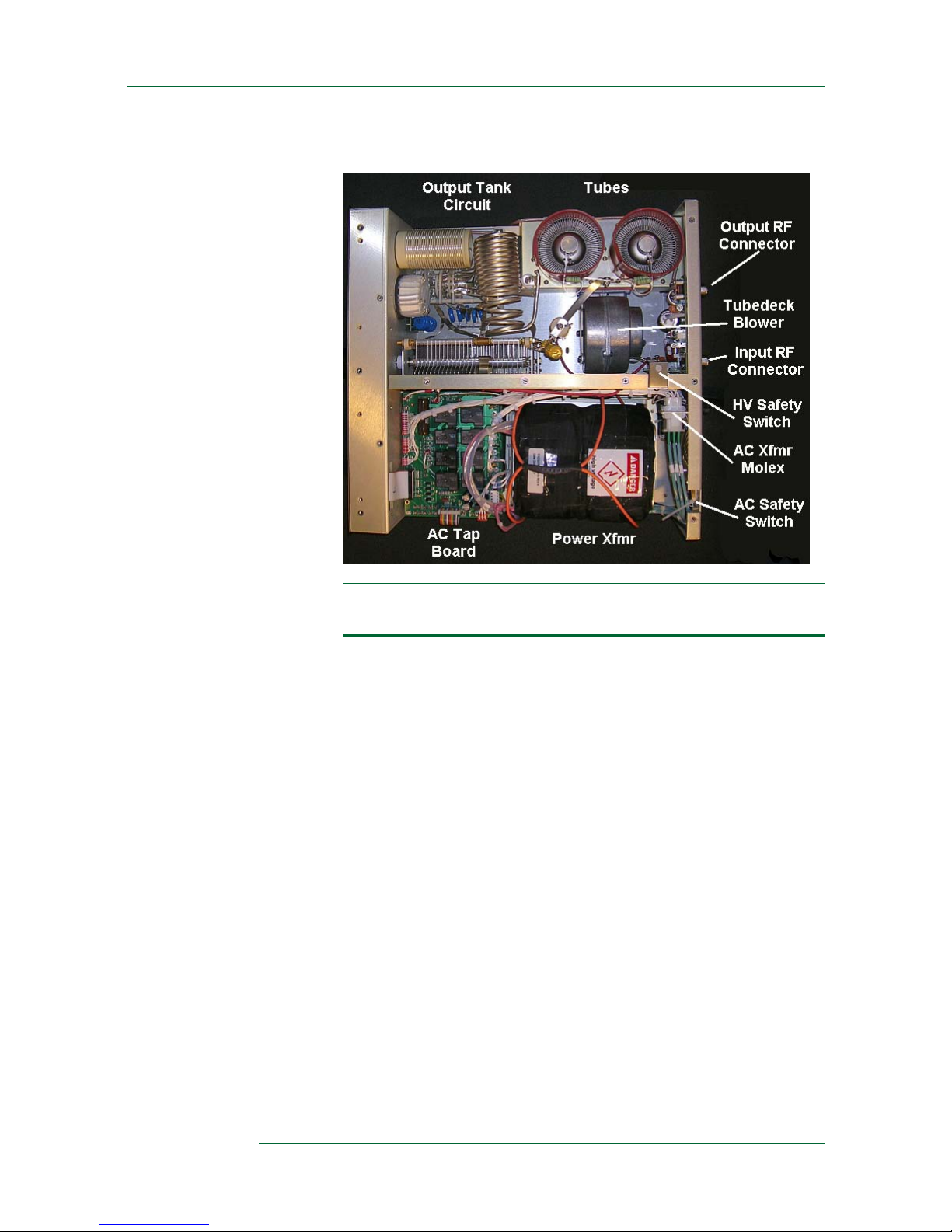
Figure 2-3 Amplifier interior (components may differ from those in
your amplifier, depending on its vintage)
2.1 Boards
The following amplifier boards are described below in alphabetical order:
•Center-partition board
•Control board
•Display board
•HV board
•Mains board
•Transmit/receive (T/R) board
•Tube-deck board
Center-Partition Board
The center-partition board contains the RF decoupling circuit on the B+
line as well as the crowbar safety circuit. When you remove the top cover
of the amplifier, the spring metal of this safety device shorts out the B+
line.

Alpha 8410 Linear Amplifier User Manual RKR Designs LLC
Amplifier Components and Specifications
DOCNUMBER 8410
Document Issue 1.1
Page 2–4 August 2015
22
2
!
IMPORTANT Do not defeat this safety circuit. It is placed there for your protection.
Control Board
The control board is the heart of the amplifier. It is based on a PIC
microcontroller. This microcontroller has a built-in multichannel analog-
to-digital converter that monitors all critical voltages and currents in the
amplifier as well as the input power and output forward and reflected
power. It uses these converted values to control the amplifier’s operation
and to drive the display board on the front panel.
A USB port on the back of the amplifier is provided for remote
monitoring. The USB driver for the amplifier is provided on the CD that
ships with the amplifier or is available at www.rksdesignsllc.com.
Display Board
The display board uses a MAX7219 LED driver chip. It receives data
from the controller via a serial peripheral interface (SPI). It contains a
regulator to drop voltage from +12 V to +5 V for the display.
HV Board
The main high voltage for the amplifier is created on the HV board using
a full-wave bridge rectifier and a bank of capacitors. This power supply
has two 10-ohm resistors, one in the positive (B+) lead and one in the
negative return that goes to ground. This combination of resistors limits
the surge current in the case of a B+ arc.
The voltage across the resistor in the negative return is used to monitor
tube plate current in the control board. It is also used to generate a hard-
fault condition. When the power-supply current exceeds ~2.5 A, a relay
opens the coil circuit of the mains tap relays on the mains board, causing
the amplifier to go to the power-off state. This hard-fault circuit operates
independently of microprocessor control.
The regulated screen supply is also located on this board.
All power-supply filter capacitors on this board have bleeder resistors that
discharge the capacitors in less than 60 seconds. If you must work on this
board, confirm the discharged condition with a voltmeter, due to the
remote possibility of bleeder resistor failure.

2
2
2
DOCNUMBER 8410
Document Issue 1.1
August 2015 Page 2–5
RKR Designs LLC Alpha 8410 Linear Amplifier User Manual
Amplifier Components and Specifications
Mains Board
Power-supply functions are split between the mains board and the HV
board. The mains board deals mostly with the primary side of the
transformer. The various taps for the transformer primary are routed
through this board and so is the AC line input. Relays on the mains board
connect the AC line to the appropriate taps on the transformer primary.
Also on the mains board is a step-start circuit. This circuit consists of a
relay and a resistor, which are time-sequenced to limit the inrush current
into the amplifier when it is first turned on. When the amplifier is initially
turned on, the tap relays operate from a voltage derived from resistors
from the AC line. They hold via contacts on the trip relay on the HV
board. The regulated –12 and –124-V supplies are also located on this
board. Many of the important voltages for the amplifier are brought to test
points on this board.
The primary voltage taps are located on the top of the mains board,
between the transformer and the front panel.There is a row of five “fast-
on” connectors (J22 through J26) and a flying jumper connector that
mates with them.
T/R Board
The transmit/receive (T/R) board contains the RF input and RF output
relays as well as the input-power detection and output directional
wattmeter. Voltages from the detector are connected to the control board.
A trimmer capacitor on this board has been adjusted at the factory with
the amplifier operating into a good 50-ohm dummy load. This capacitor
should be adjusted only at the factory.
The board also has an 800-V protection device on the RF output.
Tube-Deck Board
The tube-deck board is located in the tube deck, below the tube sockets. It
contains critical circuit elements that need to be in close proximity to the
tubes. The tube heater, bias, and screen connections are all located on this
board. Thetube-decktemperaturesensorandtheinputmatchforthe tubes
complete this board.
For more information on the tube deck, see Section 2.4, “Tubes and Tube
Deck,” page 2–6.

Alpha 8410 Linear Amplifier User Manual RKR Designs LLC
Amplifier Components and Specifications
DOCNUMBER 8410
Document Issue 1.1
Page 2–6 August 2015
22
2
2.2 Controls and Display
The Alpha 8410 controls enable you to adjust and monitor the amplifier
as needed (see Table 2-1).
Table 2-1 Amplifier controls
Control Purpose
BAND Selects an amateur band, designated in megahertz
(MHz).
LOAD Controls the load capacitor. Sets the amplifier plate
loading and determines the power level at which best
efficiency and linearity are achieved. In general,
loading is heavier at higher output power.
TUNE Controls the tune capacitor. Sets the output tank circuit
to resonance within each band. Higher frequencies tend
to tune toward the 0 end and lower frequencies toward
the 100 end of the dial scale.
2.3 Output-Tank Circuit
The output-tank circuit provides reliable high-efficiency, low-distortion
performance in a very compact volume. The basic topology is “pi-L,”
which provides harmonic attenuation adequate to meet the requirements
of all countries globally that permit power outputs of 1500 W.
Band switching is under manual control, accomplished by a 4-wafer band
switch. These wafers are used as multifunction tap selectors, which
simultaneously select band taps on the inductors and include varying
amounts of capacitance to provide band spread on the tune and load
capacitors. The wafers are in the RF tank area. A variable resistor inside
the front subchassis is used by the control board to determine which band
you have selected.
2.4 Tubes and Tube Deck
The amplifier uses two 4CX1500B (Alpha part number VTX-X120)
tetrode tubes, operating well within their ratings and in parallel.
The tubes are very rugged and normally operate with a large margin of
safety. They should provide outstanding service for many years if they are
not damaged by abuse such as overdrive or blockage of cooling airflow.

2
2
2
DOCNUMBER 8410
Document Issue 1.1
August 2015 Page 2–7
RKR Designs LLC Alpha 8410 Linear Amplifier User Manual
Amplifier Components and Specifications
The tubes are operated in Class AB1, with a plate voltage of 2800 V
(nominal, full output, key down), a grid 1 voltage of –50 to –60 (minus 50
to minus 60) V, and a grid 2 voltage of 200 V. They have a low-
inductance resistor in series with their cathodes. This resistor stabilizes
the tube bias and provides negative feedback, which improves linearity
and hence intermodulation distortion (IMD) performance. Electronic bias
switching (EBS) increases the negative grid 1 voltage in pauses in speech
or between Morse code elements. This reduces the standing bias on the
tubes, resulting in less waste heat, longer tube life, and higher overall
amplifier efficiency. The artifacts of EBS are not noticeable under normal
communications conditions.
The tubes are operated as a “swamped grid” tetrode design. The tube grids
are tied at RF to a 50-ohm swamping resistor that absorbs most of the
input-drive power. The RF voltage across this resistor is added to the
grid 1 DC bias to provide the net low-impedance tube grid 1 bias. The RF
impedance represented by grid 1 and its capacitance is compensated for
by a series inductance to provide SWR <2:1 on each band at the
amplifier’s input. At higher frequencies, a relay switches in a separate
matching network. This relay is under microprocessor control and is
actuated according to the band.
NOTE To prolong tube life, refrain from cycling AC power on-off-on-off
repeatedly. It is less stressful to leave equipment in standby for
several hours than to cycle it on and off repeatedly.
The tube deck is a mechanical assembly enclosing the tube sockets and
the tube-deck board. The tube sockets contain the integral screen grid
(grid 2) RF bypass capacitors as well as contacts for the screen, heater,
and filament of the tubes.
2.5 Specifications
The Alpha 8410 linear amplifier specifications are as follows.
Table 2-2 Alpha 8410 linear amplifier specifications
Parameter Value
Frequency coverage 1.8–29.7 KHz
Input-drive level 50 W nominal
Power output 1500 W
SWR tolerance 3:1
Duty cycle 100%
Tubes 2 4CX1500B (Alpha part number VTX-X120

Alpha 8410 Linear Amplifier User Manual RKR Designs LLC
Amplifier Components and Specifications
DOCNUMBER 8410
Document Issue 1.1
Page 2–8 August 2015
22
2
Intermodulation level 30 dB minimum, two exciter
Harmonics –50 dBc
Mode of operation CW, SSB, FM
Input AC voltage 100, 120, 200, 220, 240 selectable
AC current <15 amps @240 VAC @1500 W
Input impedance 50 ohms
Output impedance 50 ohms
RF connectors SO-239
Cooling Forced air
Size 17.3"W x 7"H x 21.0"D including fan space
Weight 70 lb (31.8 kg)
T/R relay Vacuum QSK
Tuning/band switching Manual
Display Bar-graph LED
Interface USB
Protection Against all common faults
RF bypass level <500 W
Table 2-2 Alpha 8410 linear amplifier specifications (Continued)
Parameter Value

3
DOCNUMBER 8410
Document Issue 1.1
August 2015 Page 3–1
3 Preparing Your Station
3.1 Prepare Your Station 3–1
3.2 Limitations of Operation at Nonstandard Voltage 3–4
3.1 Prepare Your Station
The Alpha 8410 is capable of dramatically improving the performance of
your amateur station. It is important that you observe good engineering
practices to achieve all the benefits of such a station in a safe and reliable
manner.
This chapter provides a few important operational considerations. We
recommend that you also consult a good source of general information
such as the latest Amateur Radio Relay League (ARRL) Handbook for
Radio Amateurs, especially if this is the first high-power amplifier that
you have used.
Procedure 3-1 Prepare your station
Step 1 Provide 240 VAC power.
The amplifier runs best when powered by a 200–240 VAC circuit. If you
do not have a 240 VAC outlet in your station, have a licensed electrical
contractor install one. A minimum of a 20 A capacity is required. A 20-A
breaker on your 240-V circuit is sufficient.
Select a location for the outlet as close as possible to where you expect to
operate the amplifier. If you are not sure or contemplate moving the
amplifier, consider installing two outlets.
The amplifier is shipped with a NEMA 6-20-style plug installed.
Ask the contractor to measure the voltage and record it for reference. If
possible, have the contractor measure the line voltage with a 10-A current
draw, and use this value for setting the transformer tap.
Although the amplifier can run when connected to a 120-VAC outlet, you
MAY NOT achieve full-legal-limit output in this case. Rather, you should
not expect more than 1000 W output. For more information on the
limitations of operation when connected to a 110 VAC outlet, see Section
3.2, “Limitations of Operation at Nonstandard Voltage,” page 3–4.
Step 2 Provide proper airflow.

Alpha 8410 Linear Amplifier User Manual RKR Designs LLC
Preparing Your Station
DOCNUMBER 8410
Document Issue 1.1
Page 3–2 August 2015
33
3
It is critical that airflow around the amplifier remain unimpeded at all
times and that the top of the amplifier remain clear of any restrictions.
Maintain at least 3 in. of clearance around the amplifier and at least 4 in.
of clearance around the air intake and exhaust areas to allow for
unobstructed airflow. Ensure that exhausted air cannot recirculate back
into the amplifier air intake. We recommend that you do not stack
equipment on top of the amplifier.
If you are mounting the amplifier in a console, ensure that the exhaust air
is properly and fully removed from the console. If outlet air is drawn back
into the amplifier air intake and recirculated, the amplifier gets hotter and
hotter, resulting in degraded performance or even failure. If you are
designing your own console, consider putting in additional fans and/or
ducting to deal with waste heat.
Minimizethepossibilityofdustor other contaminationgettingdrawninto
or falling on the amplifier. Periodically (at least annually) clean the dust
out of the amplifier, paying particular attention to the tube fins. We
recommend the use of compressed air for dust removal.
Step 3 Ready your antenna for 1500 W.
Ensure that all antennas are rated for 1500 W and that they are carefully
tuned and installed for minimum voltage SWR.
Many antennas that are suitable for general use are unsuited for operation
at full 1500-W power. At this power level in a 50-ohm circuit, the RMS
current is 5.5 A and the peak RF voltage is 387 V. For SWR = 2:1, these
valuesdoubleto11A and 775V.Theactualvoltageandcurrent at various
points in or on your antenna may actually be many times these values.
Ona simple dipolewith sharp wireends,corona(localized ionization)can
easily occur. Corona can (and has!) led to fire in nearby objects. Traps in
beams and verticals can heat up significantly during high-power
operation. Melting or flashover of traps have occurred in many
installations where insufficient thought has been given to their ratings. If
an antenna has been deployed for a long period of time, take it down for
inspection before full-power operation. If any insulators are cracked or
show signs of tracking, replace them.
Step 4 Provide adequate RF cabling.
Use good-quality low-loss coaxial cable.
Use new, clean connectors and install them according to manufacturer
recommendations. Clean the connectors after soldering them and before
mating them with the amplifier.
Remove any excess solder from the connector; likewise, remove any
fragments of braid and the like.
Table of contents
Popular Amplifier manuals by other brands


Hughes & Kettner
Hughes & Kettner RED BOX Classic operating instructions

Federal Signal Corporation
Federal Signal Corporation Rumbler 2 Installation and operation instructions

RCF
RCF MS520 user manual

ADRF
ADRF PSR-78-9537-XB manual

Denon
Denon PMA-2020AE owner's manual

Vitus Audio
Vitus Audio Masterpiece Series owner's manual


