RM Solar Combi Konverter Solar System User manual

Installation Manual
Issue 1
Combi Konverter Solar System
These instructions are specic to the integration of the RMSolar Combi Konverter system with the combi
boiler. The RMSolar instructions should be used in terms of the overall solar installation. Particular
attention should also be paid to the cylinder instructions bearing in mind that the system uses an
unvented hot water storage cylinder which still has to meet Building Regulation Part G3 installation
requirements.
The basic principles of operation are as follows:-
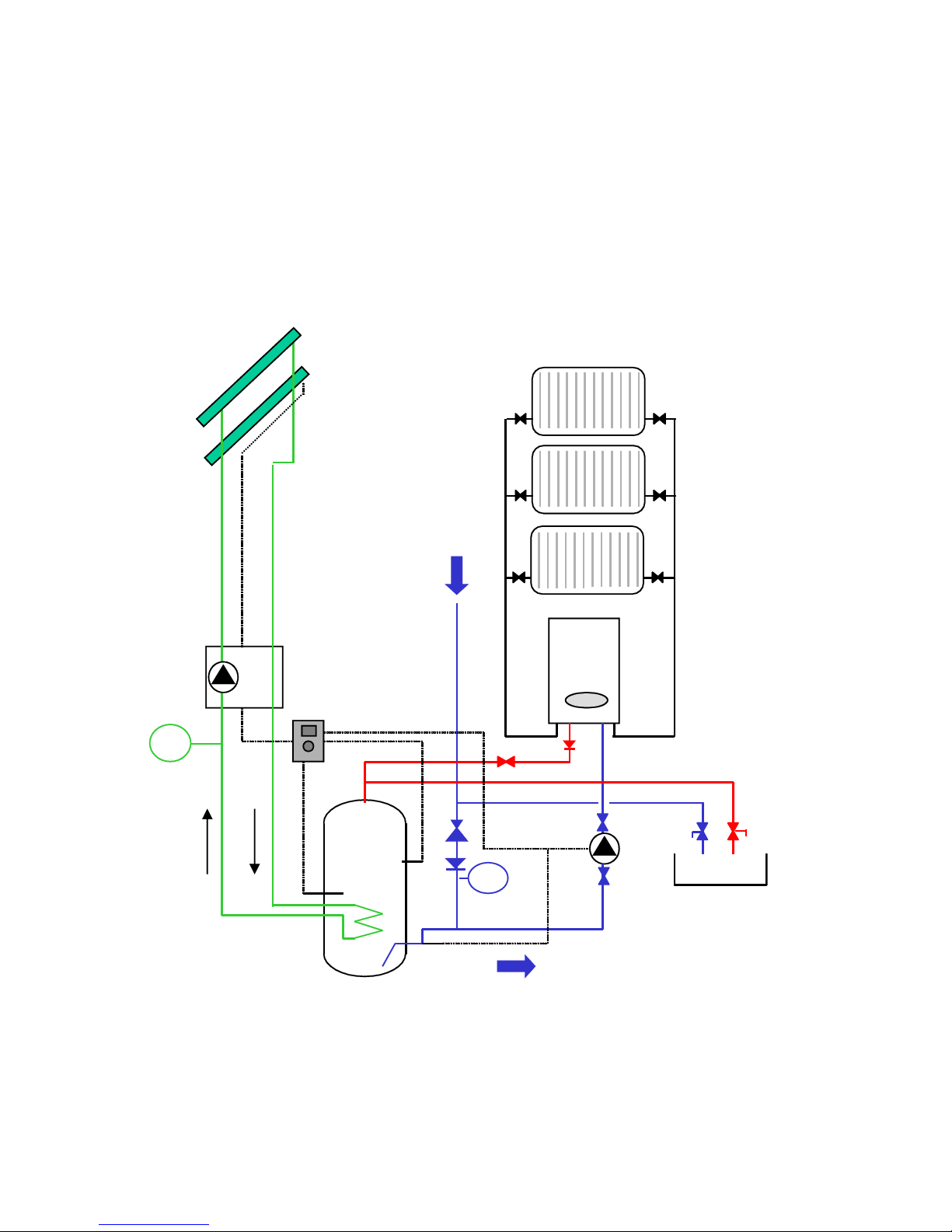
The system is shown schematically by Figs 1 and 2 using the high output domestic hot water output of
the combi to ‘charge up’ the top of the solar cylinder should insufcient solar heating be available.
Fig 1 General Schematic
In a conventional system a combi will re up on demand when it senses a ow to a hot water outlet.
In the Konverter system the combi will re up only in response to a ow through the appliance from a
circulation pump triggered by a cylinder sensor when the top of the cylinder is below a pre determined
temperature.
Panel/s
Solar
Pump
module
Combi
Taps
Cold
Feed
Radiators
Radiators
Radiators

Fig 2 Charging Sequence
Preparing for installation
The installation can be carried out by any competent person in accordance with the relevant building
regulations.
In order to properly commission the system the installer should be equipped with a suitable digital
thermometer to check ow temperatures. In most instances the combi boiler will already be in place thus
a route has to be found for additional pipe-work from the boiler to the hot water cylinder.
You will need to run two additional 22mm pipes from the boiler to the cylinder, one for the cold water feed
and one for the hot water draw off. The 22mm pipe that is allocated to the hot water draw off needs to be
adequately insulated.
As the cylinder is unvented it can be sited virtually anywhere in the dwelling but bearing in mind the likely
position of the solar panels then an upstairs position will probably be favourite.
If the combi boiler was retrotted to replace an old vented hot water storage system then a suitable site
might be the old airing cupboard. As is the case with all unvented systems the provision of a suitable
route for the discharge pipe might be the over riding factoring determining the best position.
In order for the system to operate there has to be a ow and return circuit from the combi to the cylinder
and for optimum performance the hydraulic resistance of this circuit needs to be minimised . The
circulating pump is capable of overcoming a 6 metre head resistance but some of this will be needed to
overcome the hydraulic resistance of the combi itself. This proportion will vary from combi to combi and
needs to be checked by the installer. In some circumstances it may be necessary to order an additional
bronze circulator pump to overcome the hydraulic resistance.
Before contemplating an installation the installer should check that the combi boiler is capable of
providing domestic hot water at circa 60oC. This might mean operating the appliance at a reduced
ow rate and adjusting the external and internal controls (if possible). The combis instructions or
manufacturers data should also be checked to ensure that the combi will re under conditions of low ow
and pressures of down to 0.5 bar. Some manufactures provide conversion ‘packs’ for low water pressure
areas and one of these might be required in some circumstances, normally this simply means removing
a ow restrictor.
It is advised that provision is made for a manual isolating switch on the feed to the circulation pump. This
should ideally be supplemented by the time controller provided and thought should be given to the best
position for these devices.
Connections and Pipe work
Where the combi boiler and the cylinder are in fairly close proximity with less than 5 metres of total (ow
plus return) pipe run then 15 mm copper will normally sufce. Once the length exceed this it is generally
required to use 22mm pipe. The pipe work runs should be designed to minimise hydraulic losses with
swept bends etc preferred to elbows.
The hot side (ow) of the circuit should be adequately insulated to minimise any temperature drop
between the combi and the cylinder. The cold feed (return) side of the circuit from the cylinder to the
combi should not be insulated.
The circulation circuit contains domestic hot water which may carry large amounts of dissolved air
and care should be taken to eliminate the possibility of air traps with pipe-work running as far as
possible from the boiler to the cylinder in a horizontal or uphill manner. Where this is not possible then
consideration should be given to automatic air traps or air separation devices.
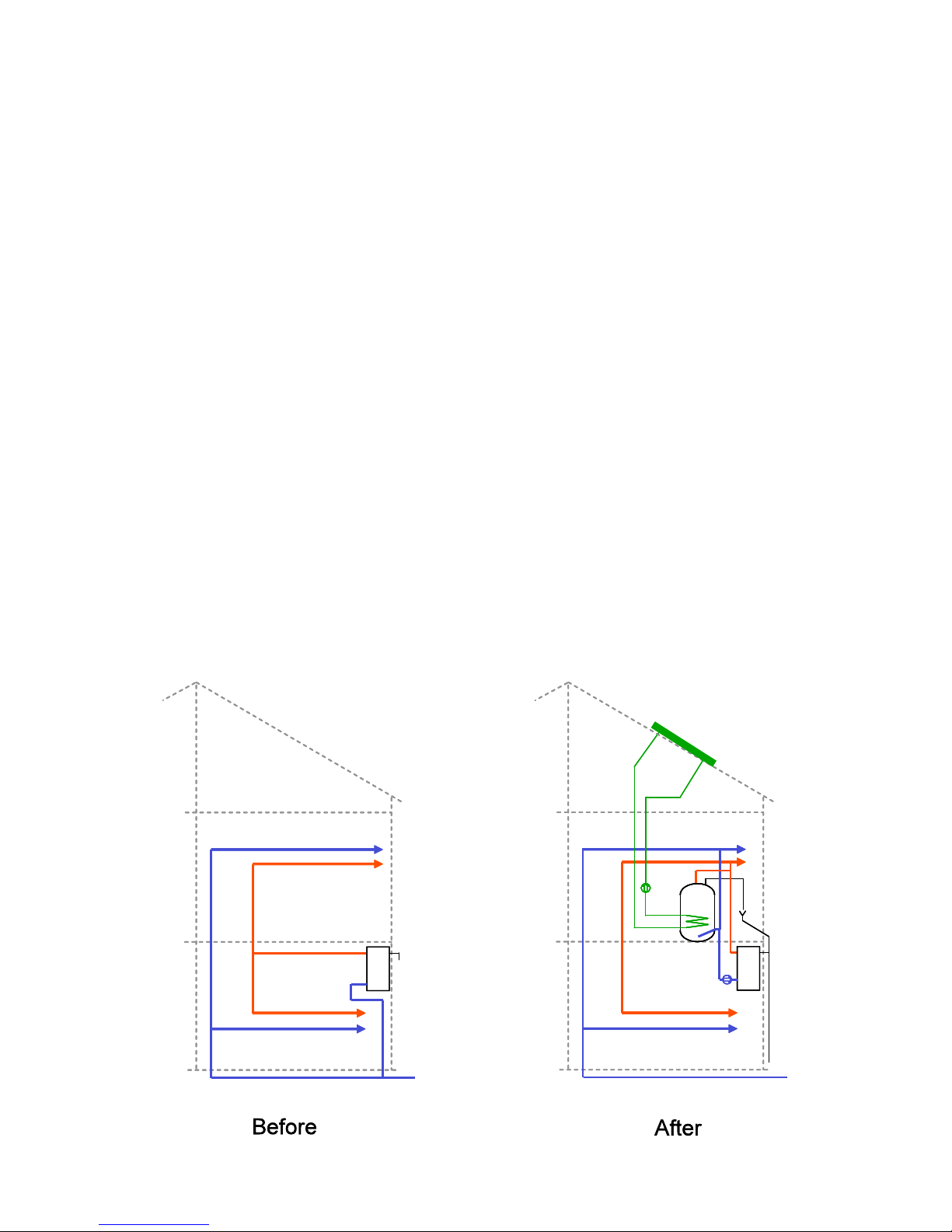
Fig 3 Typical Installation

Fig 4 Cylinder Connections
Hot Flow Pipe
The hot outlet from the Combi boiler should be piped directly to the cylinder hot draw off (there should be
no taps on this pipe that serve baths, basins, sinks ect), but should be tted with a suitable full ow gate
valve or similar so that if required the ow rate can be regulated as part of the commissioning process. In
circumstances where the combi is sited at a higher level than the cylinder then a non return valve should
be tted to the hot outlet where it exits the Combi boiler to prevent gravity circulation.
The hot water draw off at the cylinder should be tee’d into the hot water pipe coming from the Combi (as
shown in Fig 5) and then the outlets ( taps, showers ect,) connected down stream of the cylinder so that
now both the Combi and the cylinder can supply hot water on demand.
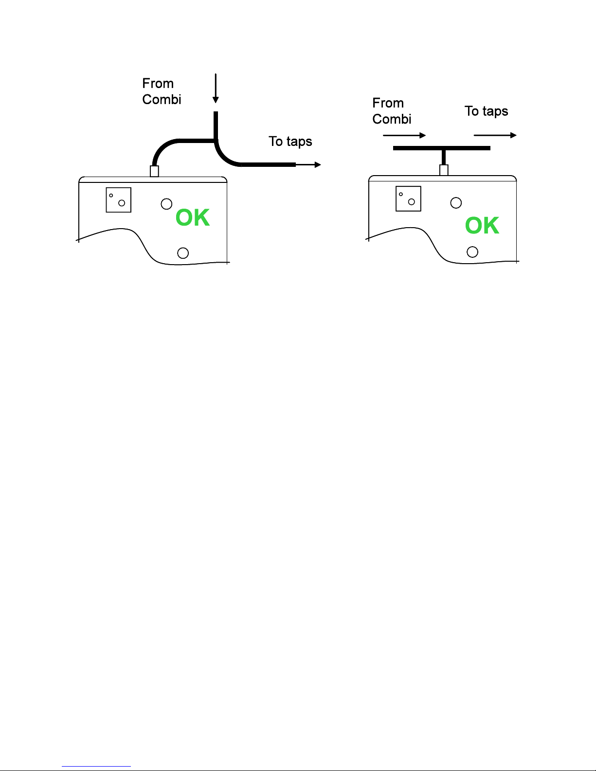
Fig 5
Cold Return Pipe
The mains cold feed needs disconnecting from the Combi boiler and a new cold feed given to the mains
pressure cylinder via the unvented inlet control set components.
(DO NOT use the 22mm pipe laid early, as instructed in Connections and Pipe work)
Connection at the cylinder should be made using the ½”x22x22mm compression tee (supplied). The
probe thermostat and pocket (supplied) are connected to this tee as illustrated. (See g 6).
Cut a Tee into the cold mains feed to the cylinder, (It is important that the Tee is connected at a point
between the unvented inlet control set components and ½”x22x22mm Tee cylinder connection see g
6) and now connect the 22mm pipe laid earlier (as instructed in connections and pipe work) to the spare
tapping on this Tee. (This pipe will be referred to as Combi cold feed from here onwards).
On the Combi cold feed pipe, install the Bronze pump and valves (supplied) with the pump ow pumping
to the Combi boiler.
Most installed combis are not tolerant to incoming ‘cold’ water temperatures of above 30oC but if in doubt
the Combi manufacturers advice on the maximum temperature should be sought . A limit thermostat (see
Fig 6) is tted on the cold feed to the cylinder, this can be set to the appropriate maximum temperature
(normally 30oC).
Where the combi is ‘solar compatible’ then this limit thermostat can be set at a higher temperature as
required.

Fig 6 Cold Inlet Thermostat
Circulation pump
The pump should always be sited with the motor spindle horizontal .Care should be taken to ensure
there is a minimum hydraulic restriction on the inlet side of the pump as this could cause a signicantly
reduced pressure zone thus encouraging dissolved air to cause pumping problems.

Wiring and Controls
The important points are as follows.
To meet G3 requirements the live feed to the solar controller circuit should be taken via the energy cut
out at the top of the cylinder.
The system should be tted with an isolating switch to disable the feed to the circulating pump, a timer is
also supplied, this should be tted in an area accesible to the end user.
Care should be taken to secure the sensors such that they can not slip out of the sensor pockets. This
can be achieved by means of a nylon tie or similar device (Fig 8)
Time switch In Series
with isolator

Fig 8 Sensor attachment
Commissioning
The important factor here is to ensure that the combi res in response to the circulation pump and
delivers water at a suitably high temperature circa 60oC.
The ow rate through the combi should be reduced to a level at which a 60oC charging temperature is
achievable. Too high a ow rate might also result in a high velocity stream of water entering the top of
the cylinder and destroying the stratication required to maintain the ‘hot top’.
In normal circumstances the pump speed should be set at either speed 2 or 3 but a certain amount of
ne tuning may be required to suit the particular installation.
The temperature setting for the combi circulation pump is achieved by programming the SHR controller
using the separate instructions provided and should be set such that the pump stops operating once it
senses water at 55oC at the upper sensor position .A digital thermometer with a thermocouple probe is
invaluable in setting up the system.
The cylinder is tted with a lower probe thermostat (g 6) which is set at the highest temperature
permitted by the combi manufacturer for cold water feed. This is typically 30oC but may be higher if the
combi is ‘solar-compatible’.

Setting the SHR controller
There are 3 settings that need to be changed in order for the system to operate correctly; -
Factory setting Re-set To
Arr - 1 2
AHO - 40.0 oC 50.0 oC
AHF - 45.0 oC 55.0 oC
Optional; -
S MX 60.0 oC Not above 75.0 oC
(S MX = The maximum store temperature achievable by solar input, if this is set above 60.0 oC then a
solar blending valve is strongly recommended on the cylinder hot outlet pipe).
Please adjust the settings in this order, see controller booklet for operating instructions.
Testing the system
Usually the hot water setting on the Combi needs to be set at maximum and the customer needs
informing that it needs leaving at this setting.
Take note of the temperature readings on the controller display panel, readings
TSTU and TSTL are the relevant ones.
When testing the system is operating correctly, sensor TSTU on the controller display (S3 g 4) should
gradually raise to 55.0 oC whilst the bronze pump and Combi boiler are running. This can take 10-
15mins depending on the boiler type. Once TSTU has reach 55.0 oC the boiler and pump will stop.
Open a hot tap and drain the cylinder until display TSTU reaches 50.0 oC then close the tap. The Combi
should re-start and continue to run until TSTU again achieves 55.0 oC then it should switch off.
Re-check the temperature of TSTL (S2 g 4), this reading should only have uctuated by 0-5 oC when
the ow rate from the bronze pump is set correctly. If the uctuation is greater that 5 oC then selecting a
lower pump speed on the Bronze pump and/or semi closing one of the Bronze pump gate valves (located
on the Combi cold feed pipe) will slow the ow rate and stop the problem. Re-test after making any
adjustments.

Hydraulic Balancing
As part of the commissioning process the installer should ensure that adequate hot temperature, albeit
at reduced ow rate, is provided from the Combi under conditions when the cylinder is depleted of hot
water. To ensure this, it is essential that the hydraulic resistance through the Combi circuit is such that
at the point where the ows from the cylinder and Combi combine, the Combi ow circuit will have
a sufcient pressure differential to prevent excessive cooling of the combined ow due to cold water
emerging from the cylinder
Handing over the system
Following commissioning it is important that the householder is made aware of the basic operation of the
system including the end user adjustable settings on the solar controller.
It should be explained to the householder that in situations where low levels of solar input coincide with a
high hot water demand such as bath lling, the hot water delivery characteristics will change signicantly
once the pre-charge of water from the cylinder is exhausted. Under these circumstances by reducing the
ow at the tap (semi-closing the tap) the water temperature will increase to a usable temperature.
Under these circumstances a continuous ow of hot water can still be maintained albeit at a reduced ow
rate.
Optional Blender
If the Combi is known to be solar compatible then an optional blender (see g 7) can be used with an
outlet temperature set to the maximum permissible inlet temperature of the Combi. This is connected
using the ‘spare’ 22mm male connection on the cylinder (see Fig 9).
Fig 9 – Optional Blender
The same option can also be used with most other combis provided the blender set outlet temperature
does not exceed 30oC.

RM Solar Ltd
Unit 4, Gilcar Way, Wakeeld Europort, Castleford WF10 5QS
Tel: 01924 224282 Fax: 01924 224283 Web: www.rmsolar.com
Popular Water Heater manuals by other brands

Vaughn
Vaughn Hydrastone ME Series Operation and installation manual

Rheem
Rheem MPi 551 Series Owner's guide and installation instructions

A.O. Smith
A.O. Smith GCV300 Service handbook

Atmor
Atmor Enjoy Installation and operation guide

Rinnai
Rinnai RV53E Operation and installation manual

Bradford White
Bradford White 203-B Specifications

EcoSpring
EcoSpring ES300 Installation & owner's manual

Aspes
Aspes ATE30S Instructions for use and maintenance

Dimplex
Dimplex Edel 200 WATER/3 installation manual

Watts
Watts Aerco INN 600N manual

Bosch
Bosch BH 120-5 Installation and maintenance instructions for the contractor

Enertech
Enertech WS036 Installation & operation manual


