RME Audio 12Mic-D User manual

12V - 2.5A
Microphone Preamp
User’s Guide
12Mic-D
12-Channel digitally controlled
Microphone Preamplifier with Dante, ADAT and MADI
DANTE | MADI

RME 12Mic-D User’s Guide

Table of Contents
1. Safety Precautions . . . . . . . . . . . . . . . . . . . . . . . . . . . . . . . . . . . . . . . . . . . . . . . . . . . . . . . . . . . . . . . . . . . . . . . Ê1
2. Introduction. . . . . . . . . . . . . . . . . . . . . . . . . . . . . . . . . . . . . . . . . . . . . . . . . . . . . . . . . . . . . . . . . . . . . . . . . . . . . Ê2
2.1. About This Manual . . . . . . . . . . . . . . . . . . . . . . . . . . . . . . . . . . . . . . . . . . . . . . . . . . . . . . . . . . . . . . . . . . Ê2
2.2. Firmware Update . . . . . . . . . . . . . . . . . . . . . . . . . . . . . . . . . . . . . . . . . . . . . . . . . . . . . . . . . . . . . . . . . . . . Ê3
2.3. Controlling the device . . . . . . . . . . . . . . . . . . . . . . . . . . . . . . . . . . . . . . . . . . . . . . . . . . . . . . . . . . . . . . . . Ê4
2.3.1. Sections . . . . . . . . . . . . . . . . . . . . . . . . . . . . . . . . . . . . . . . . . . . . . . . . . . . . . . . . . . . . . . . . . . . . . . . Ê4
2.3.2. Tabs . . . . . . . . . . . . . . . . . . . . . . . . . . . . . . . . . . . . . . . . . . . . . . . . . . . . . . . . . . . . . . . . . . . . . . . . . . Ê5
2.4. Status Indicator Color Chart. . . . . . . . . . . . . . . . . . . . . . . . . . . . . . . . . . . . . . . . . . . . . . . . . . . . . . . . . . . Ê5
3. Hardware . . . . . . . . . . . . . . . . . . . . . . . . . . . . . . . . . . . . . . . . . . . . . . . . . . . . . . . . . . . . . . . . . . . . . . . . . . . . . . . Ê7
3.1. Hardware Specifications . . . . . . . . . . . . . . . . . . . . . . . . . . . . . . . . . . . . . . . . . . . . . . . . . . . . . . . . . . . . . Ê8
3.2. Package Contents . . . . . . . . . . . . . . . . . . . . . . . . . . . . . . . . . . . . . . . . . . . . . . . . . . . . . . . . . . . . . . . . . . . Ê8
3.3. Power On . . . . . . . . . . . . . . . . . . . . . . . . . . . . . . . . . . . . . . . . . . . . . . . . . . . . . . . . . . . . . . . . . . . . . . . . . . Ê8
3.4. Standby Switch . . . . . . . . . . . . . . . . . . . . . . . . . . . . . . . . . . . . . . . . . . . . . . . . . . . . . . . . . . . . . . . . . . . . . Ê9
3.5. Standby Indicator. . . . . . . . . . . . . . . . . . . . . . . . . . . . . . . . . . . . . . . . . . . . . . . . . . . . . . . . . . . . . . . . . . . . Ê9
3.6. Analog Input Connectors . . . . . . . . . . . . . . . . . . . . . . . . . . . . . . . . . . . . . . . . . . . . . . . . . . . . . . . . . . . . Ê10
3.6.1. Analog Input Specifications . . . . . . . . . . . . . . . . . . . . . . . . . . . . . . . . . . . . . . . . . . . . . . . . . . . . . Ê10
3.7. Frequency and Impulse Response . . . . . . . . . . . . . . . . . . . . . . . . . . . . . . . . . . . . . . . . . . . . . . . . . . . . Ê11
3.8. Analog Input LEDs with Integrated Metering . . . . . . . . . . . . . . . . . . . . . . . . . . . . . . . . . . . . . . . . . . . . Ê11
3.9. LED Meters Color and Intensity Reference. . . . . . . . . . . . . . . . . . . . . . . . . . . . . . . . . . . . . . . . . . . . . . Ê11
3.10. Control Section . . . . . . . . . . . . . . . . . . . . . . . . . . . . . . . . . . . . . . . . . . . . . . . . . . . . . . . . . . . . . . . . . . . Ê12
3.11. Headphone Output . . . . . . . . . . . . . . . . . . . . . . . . . . . . . . . . . . . . . . . . . . . . . . . . . . . . . . . . . . . . . . . . Ê13
3.11.1. Analog Output Specifications . . . . . . . . . . . . . . . . . . . . . . . . . . . . . . . . . . . . . . . . . . . . . . . . . . . Ê13
3.12. Power supply . . . . . . . . . . . . . . . . . . . . . . . . . . . . . . . . . . . . . . . . . . . . . . . . . . . . . . . . . . . . . . . . . . . . . Ê14
3.13. MADI Coaxial and SFP . . . . . . . . . . . . . . . . . . . . . . . . . . . . . . . . . . . . . . . . . . . . . . . . . . . . . . . . . . . . . Ê15
3.14. Network Connection . . . . . . . . . . . . . . . . . . . . . . . . . . . . . . . . . . . . . . . . . . . . . . . . . . . . . . . . . . . . . . . Ê16
3.15. Word Clock. . . . . . . . . . . . . . . . . . . . . . . . . . . . . . . . . . . . . . . . . . . . . . . . . . . . . . . . . . . . . . . . . . . . . . . Ê17
3.16. USB 2.0 Type B Jack. . . . . . . . . . . . . . . . . . . . . . . . . . . . . . . . . . . . . . . . . . . . . . . . . . . . . . . . . . . . . . . Ê18
3.17. ADAT Outputs . . . . . . . . . . . . . . . . . . . . . . . . . . . . . . . . . . . . . . . . . . . . . . . . . . . . . . . . . . . . . . . . . . . . Ê18
3.18. Mounting the Rack Adapter Brackets . . . . . . . . . . . . . . . . . . . . . . . . . . . . . . . . . . . . . . . . . . . . . . . . . Ê19
4. Accessories . . . . . . . . . . . . . . . . . . . . . . . . . . . . . . . . . . . . . . . . . . . . . . . . . . . . . . . . . . . . . . . . . . . . . . . . . . . Ê20
5. Dante Connectivity . . . . . . . . . . . . . . . . . . . . . . . . . . . . . . . . . . . . . . . . . . . . . . . . . . . . . . . . . . . . . . . . . . . . . . Ê21
5.1. Identifying a Device Remotely . . . . . . . . . . . . . . . . . . . . . . . . . . . . . . . . . . . . . . . . . . . . . . . . . . . . . . . . Ê21
5.2. Changing the Device Name . . . . . . . . . . . . . . . . . . . . . . . . . . . . . . . . . . . . . . . . . . . . . . . . . . . . . . . . . . Ê22
6. Warranty and Support . . . . . . . . . . . . . . . . . . . . . . . . . . . . . . . . . . . . . . . . . . . . . . . . . . . . . . . . . . . . . . . . . . . Ê23
6.1. Warranty . . . . . . . . . . . . . . . . . . . . . . . . . . . . . . . . . . . . . . . . . . . . . . . . . . . . . . . . . . . . . . . . . . . . . . . . . . Ê23
6.2. Support . . . . . . . . . . . . . . . . . . . . . . . . . . . . . . . . . . . . . . . . . . . . . . . . . . . . . . . . . . . . . . . . . . . . . . . . . . . Ê23
6.3. Support Contacts. . . . . . . . . . . . . . . . . . . . . . . . . . . . . . . . . . . . . . . . . . . . . . . . . . . . . . . . . . . . . . . . . . . Ê24
7. STATE Section . . . . . . . . . . . . . . . . . . . . . . . . . . . . . . . . . . . . . . . . . . . . . . . . . . . . . . . . . . . . . . . . . . . . . . . . . Ê25
7.1. Presets . . . . . . . . . . . . . . . . . . . . . . . . . . . . . . . . . . . . . . . . . . . . . . . . . . . . . . . . . . . . . . . . . . . . . . . . . . . Ê25
7.1.1. Saving Presets . . . . . . . . . . . . . . . . . . . . . . . . . . . . . . . . . . . . . . . . . . . . . . . . . . . . . . . . . . . . . . . . Ê27
7.1.2. Loading Presets . . . . . . . . . . . . . . . . . . . . . . . . . . . . . . . . . . . . . . . . . . . . . . . . . . . . . . . . . . . . . . . Ê29
7.1.3. Loading Factory Default Settings . . . . . . . . . . . . . . . . . . . . . . . . . . . . . . . . . . . . . . . . . . . . . . . . . Ê29
7.2. Device Lock . . . . . . . . . . . . . . . . . . . . . . . . . . . . . . . . . . . . . . . . . . . . . . . . . . . . . . . . . . . . . . . . . . . . . . . Ê29
7.2.1. Locking the Device . . . . . . . . . . . . . . . . . . . . . . . . . . . . . . . . . . . . . . . . . . . . . . . . . . . . . . . . . . . . . Ê30
7.2.2. Unlocking the Device . . . . . . . . . . . . . . . . . . . . . . . . . . . . . . . . . . . . . . . . . . . . . . . . . . . . . . . . . . . Ê30
7.3. Front Panel Illumination . . . . . . . . . . . . . . . . . . . . . . . . . . . . . . . . . . . . . . . . . . . . . . . . . . . . . . . . . . . . . Ê31

7.3.1. Dark Mode . . . . . . . . . . . . . . . . . . . . . . . . . . . . . . . . . . . . . . . . . . . . . . . . . . . . . . . . . . . . . . . . . . . . Ê31
7.3.2. Changing the Meters to Peak or RMS Mode . . . . . . . . . . . . . . . . . . . . . . . . . . . . . . . . . . . . . . . . Ê33
7.3.3. Persistent Clipping Notifications and Peak Hold . . . . . . . . . . . . . . . . . . . . . . . . . . . . . . . . . . . . Ê34
7.3.4. Metering of Digital Signals . . . . . . . . . . . . . . . . . . . . . . . . . . . . . . . . . . . . . . . . . . . . . . . . . . . . . . Ê37
7.4. Remote Control Overview. . . . . . . . . . . . . . . . . . . . . . . . . . . . . . . . . . . . . . . . . . . . . . . . . . . . . . . . . . . . Ê38
7.4.1. Finding the Device on a Network . . . . . . . . . . . . . . . . . . . . . . . . . . . . . . . . . . . . . . . . . . . . . . . . . Ê38
7.4.2. Static IP Address . . . . . . . . . . . . . . . . . . . . . . . . . . . . . . . . . . . . . . . . . . . . . . . . . . . . . . . . . . . . . . Ê39
7.4.3. Web Remote . . . . . . . . . . . . . . . . . . . . . . . . . . . . . . . . . . . . . . . . . . . . . . . . . . . . . . . . . . . . . . . . . . Ê40
7.4.4. JSON(OSC) Remote Control . . . . . . . . . . . . . . . . . . . . . . . . . . . . . . . . . . . . . . . . . . . . . . . . . . . . . Ê41
7.4.5. JSON(OSC) Implementation Chart . . . . . . . . . . . . . . . . . . . . . . . . . . . . . . . . . . . . . . . . . . . . . . . . Ê43
7.5. Device Information . . . . . . . . . . . . . . . . . . . . . . . . . . . . . . . . . . . . . . . . . . . . . . . . . . . . . . . . . . . . . . . . . Ê44
7.6. Power State . . . . . . . . . . . . . . . . . . . . . . . . . . . . . . . . . . . . . . . . . . . . . . . . . . . . . . . . . . . . . . . . . . . . . . . Ê44
7.6.1. Notification of Single Power Failure. . . . . . . . . . . . . . . . . . . . . . . . . . . . . . . . . . . . . . . . . . . . . . . Ê46
8. INPUT Section. . . . . . . . . . . . . . . . . . . . . . . . . . . . . . . . . . . . . . . . . . . . . . . . . . . . . . . . . . . . . . . . . . . . . . . . . . Ê47
8.1. Analog Inputs. . . . . . . . . . . . . . . . . . . . . . . . . . . . . . . . . . . . . . . . . . . . . . . . . . . . . . . . . . . . . . . . . . . . . . Ê47
8.1.1. Analog Input User Interfaces. . . . . . . . . . . . . . . . . . . . . . . . . . . . . . . . . . . . . . . . . . . . . . . . . . . . . Ê48
8.1.2. Adjusting the Input Gain . . . . . . . . . . . . . . . . . . . . . . . . . . . . . . . . . . . . . . . . . . . . . . . . . . . . . . . . Ê48
8.1.3. Enabling Phantom Power (P48) . . . . . . . . . . . . . . . . . . . . . . . . . . . . . . . . . . . . . . . . . . . . . . . . . . Ê50
8.1.4. Switching Between XLR and TRS Inputs . . . . . . . . . . . . . . . . . . . . . . . . . . . . . . . . . . . . . . . . . . . Ê51
8.1.5. Activating High Impedance (Hi-Z) on TRS Inputs . . . . . . . . . . . . . . . . . . . . . . . . . . . . . . . . . . . . Ê52
8.1.6. Inverting the Phase of an Analog Input Signal . . . . . . . . . . . . . . . . . . . . . . . . . . . . . . . . . . . . . . Ê54
8.1.7. AutoSet . . . . . . . . . . . . . . . . . . . . . . . . . . . . . . . . . . . . . . . . . . . . . . . . . . . . . . . . . . . . . . . . . . . . . . Ê54
8.1.8. Activating AutoSet . . . . . . . . . . . . . . . . . . . . . . . . . . . . . . . . . . . . . . . . . . . . . . . . . . . . . . . . . . . . . Ê55
8.1.9. Gain Groups. . . . . . . . . . . . . . . . . . . . . . . . . . . . . . . . . . . . . . . . . . . . . . . . . . . . . . . . . . . . . . . . . . . Ê56
8.1.10. Creation and Use of a Gain Group . . . . . . . . . . . . . . . . . . . . . . . . . . . . . . . . . . . . . . . . . . . . . . . Ê57
8.1.11. Saving, Using and Deleting Gain Groups . . . . . . . . . . . . . . . . . . . . . . . . . . . . . . . . . . . . . . . . . . Ê58
8.1.12. Monitor Analog Inputs at Phones Output . . . . . . . . . . . . . . . . . . . . . . . . . . . . . . . . . . . . . . . . . Ê59
8.2. MADI Inputs . . . . . . . . . . . . . . . . . . . . . . . . . . . . . . . . . . . . . . . . . . . . . . . . . . . . . . . . . . . . . . . . . . . . . . . Ê60
8.2.1. MADI at High Sample Rates . . . . . . . . . . . . . . . . . . . . . . . . . . . . . . . . . . . . . . . . . . . . . . . . . . . . . Ê61
8.2.2. Connecting Two Identical MADI Signals for Redundancy . . . . . . . . . . . . . . . . . . . . . . . . . . . . . Ê61
8.3. Dante Input. . . . . . . . . . . . . . . . . . . . . . . . . . . . . . . . . . . . . . . . . . . . . . . . . . . . . . . . . . . . . . . . . . . . . . . . Ê62
9. OUTPUT Section. . . . . . . . . . . . . . . . . . . . . . . . . . . . . . . . . . . . . . . . . . . . . . . . . . . . . . . . . . . . . . . . . . . . . . . . Ê64
9.1. Routing Signals to the Outputs . . . . . . . . . . . . . . . . . . . . . . . . . . . . . . . . . . . . . . . . . . . . . . . . . . . . . . . Ê65
9.2. Analog Outputs . . . . . . . . . . . . . . . . . . . . . . . . . . . . . . . . . . . . . . . . . . . . . . . . . . . . . . . . . . . . . . . . . . . . Ê66
9.2.1. Phones Out . . . . . . . . . . . . . . . . . . . . . . . . . . . . . . . . . . . . . . . . . . . . . . . . . . . . . . . . . . . . . . . . . . . Ê66
9.2.2. Adjusting the Headphone Volume . . . . . . . . . . . . . . . . . . . . . . . . . . . . . . . . . . . . . . . . . . . . . . . . Ê67
9.2.3. Muting the Phones Output. . . . . . . . . . . . . . . . . . . . . . . . . . . . . . . . . . . . . . . . . . . . . . . . . . . . . . . Ê68
9.2.4. Using Phones Out as a Balanced Line Output. . . . . . . . . . . . . . . . . . . . . . . . . . . . . . . . . . . . . . . Ê68
9.3. MADI Outputs. . . . . . . . . . . . . . . . . . . . . . . . . . . . . . . . . . . . . . . . . . . . . . . . . . . . . . . . . . . . . . . . . . . . . . Ê69
9.3.1. Setting the Output Channel Format and Frame Pattern. . . . . . . . . . . . . . . . . . . . . . . . . . . . . . . Ê69
9.3.2. MADI Daisy Chains . . . . . . . . . . . . . . . . . . . . . . . . . . . . . . . . . . . . . . . . . . . . . . . . . . . . . . . . . . . . . Ê70
9.3.3. MADI Port Mirroring . . . . . . . . . . . . . . . . . . . . . . . . . . . . . . . . . . . . . . . . . . . . . . . . . . . . . . . . . . . . Ê70
9.4. Dante Output . . . . . . . . . . . . . . . . . . . . . . . . . . . . . . . . . . . . . . . . . . . . . . . . . . . . . . . . . . . . . . . . . . . . . . Ê71
9.5. ADAT Outputs . . . . . . . . . . . . . . . . . . . . . . . . . . . . . . . . . . . . . . . . . . . . . . . . . . . . . . . . . . . . . . . . . . . . . Ê71
10. CLOCK Section . . . . . . . . . . . . . . . . . . . . . . . . . . . . . . . . . . . . . . . . . . . . . . . . . . . . . . . . . . . . . . . . . . . . . . . . Ê72
10.1. Clock Status. . . . . . . . . . . . . . . . . . . . . . . . . . . . . . . . . . . . . . . . . . . . . . . . . . . . . . . . . . . . . . . . . . . . . . Ê72
10.2. Leader Clock . . . . . . . . . . . . . . . . . . . . . . . . . . . . . . . . . . . . . . . . . . . . . . . . . . . . . . . . . . . . . . . . . . . . . Ê72
10.2.1. Synchronizing to External . . . . . . . . . . . . . . . . . . . . . . . . . . . . . . . . . . . . . . . . . . . . . . . . . . . . . . Ê74

10.3. Sample Rates Overview . . . . . . . . . . . . . . . . . . . . . . . . . . . . . . . . . . . . . . . . . . . . . . . . . . . . . . . . . . . . Ê74
10.3.1. Number of Channels . . . . . . . . . . . . . . . . . . . . . . . . . . . . . . . . . . . . . . . . . . . . . . . . . . . . . . . . . . Ê75
10.3.2. Number of Channels . . . . . . . . . . . . . . . . . . . . . . . . . . . . . . . . . . . . . . . . . . . . . . . . . . . . . . . . . . Ê75
10.3.3. Selecting a Sample Rate . . . . . . . . . . . . . . . . . . . . . . . . . . . . . . . . . . . . . . . . . . . . . . . . . . . . . . . Ê75
10.3.4. Effects of Sample Rate Changes on Existing Routing . . . . . . . . . . . . . . . . . . . . . . . . . . . . . . . Ê76
10.4. Set Word Clock Output to Single Speed . . . . . . . . . . . . . . . . . . . . . . . . . . . . . . . . . . . . . . . . . . . . . . . Ê77
11. Annex. . . . . . . . . . . . . . . . . . . . . . . . . . . . . . . . . . . . . . . . . . . . . . . . . . . . . . . . . . . . . . . . . . . . . . . . . . . . . . . . Ê78
Glossary . . . . . . . . . . . . . . . . . . . . . . . . . . . . . . . . . . . . . . . . . . . . . . . . . . . . . . . . . . . . . . . . . . . . . . . . . . . . . . Ê79
11.1. Regulatory Compliance . . . . . . . . . . . . . . . . . . . . . . . . . . . . . . . . . . . . . . . . . . . . . . . . . . . . . . . . . . . . Ê79
11.1.1. CE Compliance . . . . . . . . . . . . . . . . . . . . . . . . . . . . . . . . . . . . . . . . . . . . . . . . . . . . . . . . . . . . . . . Ê79
11.1.2. FCC Compliance. . . . . . . . . . . . . . . . . . . . . . . . . . . . . . . . . . . . . . . . . . . . . . . . . . . . . . . . . . . . . . Ê79
11.1.3. Note on Disposal . . . . . . . . . . . . . . . . . . . . . . . . . . . . . . . . . . . . . . . . . . . . . . . . . . . . . . . . . . . . . Ê80

1. Safety Precautions
WARNING
DO NOT OPEN DEVICE - RISK OF ELECTRIC SHOCK
The unit has non-isolated live parts inside. No user serviceable parts inside. Refer
service to qualified service personnel.
CAUTION
General Safety Information
Read read the following safety information thoroughly and keep it in a safe place
for later reference.
KEEP AWAY FROM WATER AND MOISTURE
Prevent moisture and water from entering the device. Never leave objects
containing liquid on top or near the device. Do not use this product near water, i. e.
swimming pool, bathtub or wet basement. Danger of condensation inside - do not
turn on before the device has reached room temperature.
ENSURE PROPER VENTILATION
Do not cover the vents on the side of the unit. Ensure proper ventilation to avoid
overheating. The maximum ambient operating temperature of the device is 35° C
(95° F).
MAINS
The apparatus shall be connected to a mains socket outlet with a protective
earthing connection. Do not use defective power cords. Ensure that the AC socket
outlet for the device or an external power supply is easily accessible.
Operation of the device is limited to the description in this manual.
NOTICE
Read the User Manual
Read the manual completely before using the product. It includes all information
necessary to use and operate this device.
RME 12Mic-D User’s Guide
1| 1. Safety Precautions

2. Introduction
Thank you for purchasing the 12Mic-D.
The 12Mic-D is a 12 channel microphone preamplifier designed to be the centerpiece of any professional
recording. Among its outstanding features: digital no-compromise studio quality converters, remote
control, integrated Dante® and MADI connectivity, and a user interface optimized for rapid configuration
and control.
While all 12 front-facing XLR connectors accept microphone and line level signals, the first four
connectors also accept TRS connectors with switchable high impedance (Hi-Z) for instruments. The
PAD-free microphone input stages have a 75 dB gain range and accept signals of up to +18 dBu.
The device state can be inspected and modified directly on the front panel with an encoder knob, a
display, four buttons that change their function depending on the current feature, and a button on each
input channel. It is possible to rapidly create gain groups, switch phantom power and route signals to the
headphone without entering complex submenus.
By integrating Audinate’s Dante® IP Core on a custom built RME FPGA platform, RME is not only
delivering a highly flexible solution but also gets one step closer to achieving a truly universal Audio
Networking experience. Any signal reaching the 12Mic-D can be routed and streamed over IP networks,
including MADI signals!
The coaxial MADI port and a slot for a second, independent or redundant optical MADI port (SFP module)
can be used for daisy chaining, merging and converting MADI signals with lowest latencies. In addition,
three optical ADAT output ports for up to 24 chanels at single speed (for example a combination of
microphone inputs, MADI signals and Dante® signals) or 12 outputs at 96 kHz sampling rate offer
compatibility to a wide range of audio interfaces.
Multiple layers of redundancy make this product the perfect fit for live sound applications. Two fully
redundant network ports are implemented for Dante® redundancy. The MADI ports support RME’s MADI
redundancy implementation. And even the power inlet allows for redundancy with an optional external
DC power supply in addition to the IEC connector.
A web frontend offers convenient access to the device controls and its integrated routing matrix. The
integrated matrix allows free routing between analog inputs and headphone outputs, as well as all
channels of both MADI ports, Dante®, and three ADAT outputs.
2.1. About This Manual
This document was created for firmware 1.0.3 on 2022-10-24. For an updated firmware, please check
https://www.rme-audio.com.
This manual is also available online, with extended information on using the web remote.
Please visit https://docs.rme-audio.com/12micd.
The following manual provides a detailed explanation of features and their proper use. Please read the
safety instructions carefully.
Features described in this manual may change when the device firmware is updated. It is
therefore recommended to refer to the latest version of the manual available online.
Although the contents of this manual have been thoroughly checked for errors, RME cannot guarantee
that it is correct throughout. RME does not accept responsibility for any misleading or incorrect
RME 12Mic-D User’s Guide
2. Introduction | 2

information within this guide. RME reserves the right to change specifications at any time without notice.
2.2. Firmware Update
New and improved features for this device, as well as bug fixes, are published on the RME website in the
download section as a firmware update. The update is provided as a compressed file with a .swu
extension and can be uploaded via web remote over USB or network.
To update the 12Mic-D:
1. Connect the device by USB or network cable and open the Web Remote.
See: web remote
2. Download the current firmware from the RME website.
3. Unpack the compressed file.
4. Open the Settings in the Web Remote.
5. Within the Firmware Update section, press the Select .swu Firmware File Êbutton and locate the
unpacked file.
6. Press Start Firmware Update .
The unit retains all settings, including presets, when the firmware is upgraded.
RME 12Mic-D User’s Guide
3| 2.2. Firmware Update
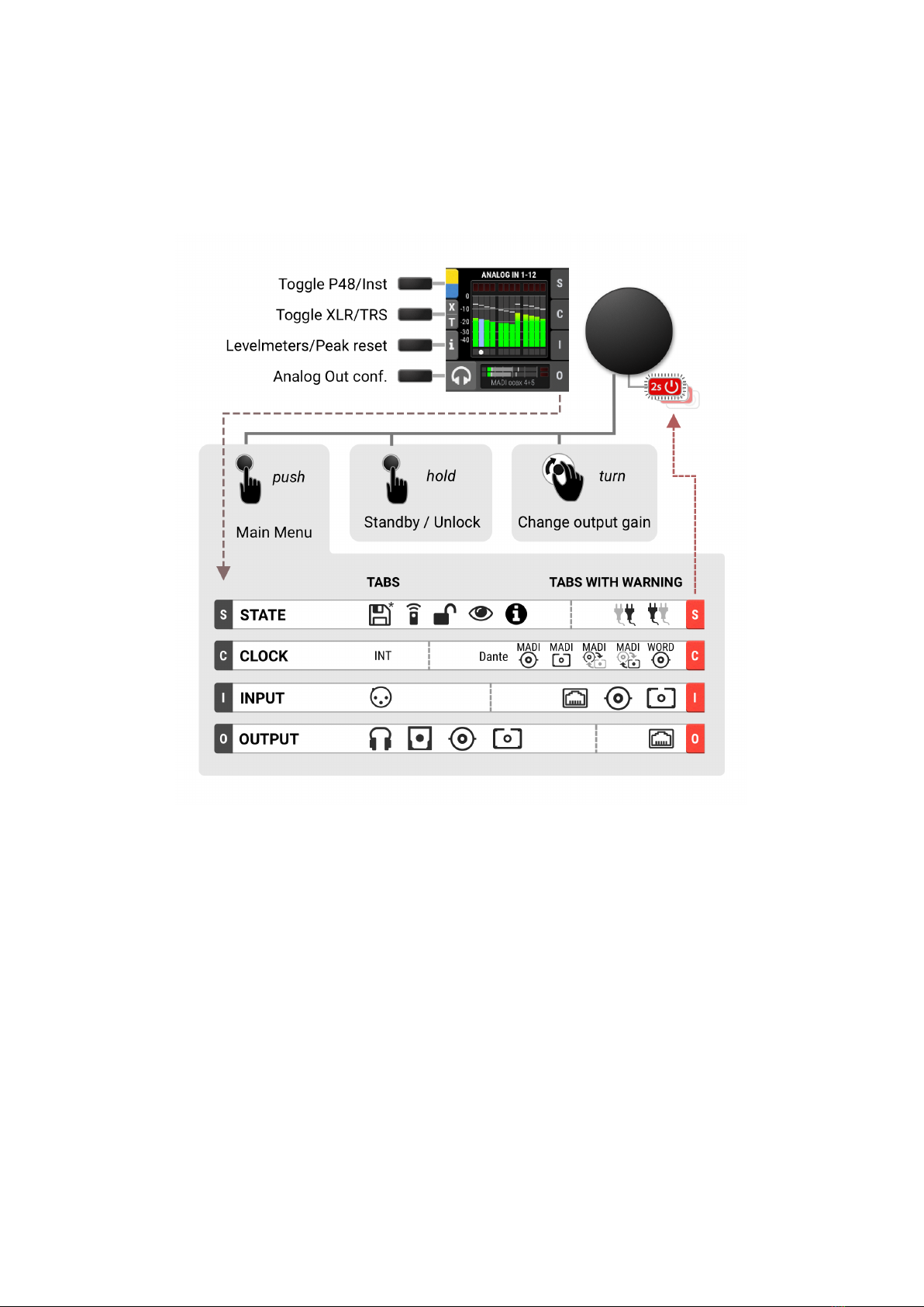
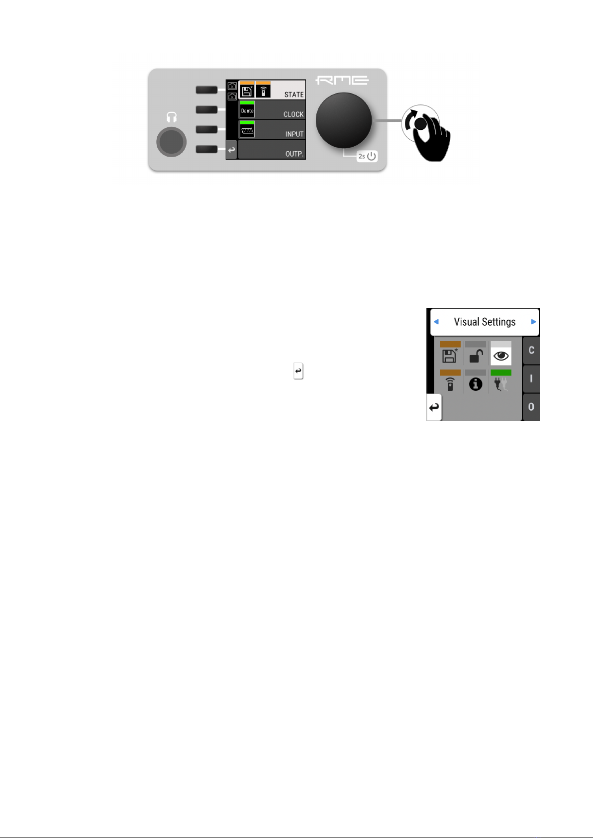
2.3. Controlling the device
The 12Mic-D can be controlled directly at the unit. For this purpose, a display, buttons, and an encoder
provide access to all features. From the main screen, the encoder knob is used to access the main menu.
It also controls the gain of the headphone output if turned, and puts the device into standby mode if
pushed for several seconds.
2.3.1. Sections
The main menu separates all controls into one of four sections:
•STATE for general settings
•CLOCK for digital clock related settings
•INPUT for audio input related settings
•OUTPUT for audio output related settings and routing
RME 12Mic-D User’s Guide
2.3. Controlling the device | 4
To access the INPUT section:
1. Push the encoder to open the menu
2. Rotate the encoder to highlight the "INPUT" section
3. Push the encoder to open the "INPUT" section.
2.3.2. Tabs
The STATE, INPUT and OUTPUT sections are further divided into tabs,
which are shown when the section is opened. Upon opening one of these
sections, a cursor is shown to navigate between tabs and settings.
To leave a tab or the section, use the return button: .
Tabs can generate a warning whenever a configured signal path cannot be established. This is then
indicated on the main screen as a red highlight of the corresponding section and in the main menu.
Warnings occur for example when a clock reference signal does not match the internal sample rate. They
also cause the standby LED to flash in white and red.
Tabs in the main menu can also show a 'caution notification' (orange), for example if a modified preset
was not saved. To see these notifications, open the main menu by pushing the encoder.
2.4. Status Indicator Color Chart
Notifications on this device have been optimized for different screen sizes. They are unified across the
device display and the web remote and include a color bar that indicates the current state at a glance.
RME 12Mic-D User’s Guide
5| 2.4. Status Indicator Color Chart

The following table shows the possible status indicator colors for reference.
Status Color Description
Warning red Requires a configuration change or matching
external signal.
Notice yellow There is a potential issue.
Notice (in progress) yellow with dots There is a temporary issue that should resolve
automatically.
No Routing light green In output section: Output is sending an empty
signal.
Issues with Input light green On standby screen in output section: Output is
working, but issues with input.
Good green Everything is working as expected.
Inactive grey Feature is not monitored or disabled.
RME 12Mic-D User’s Guide
2.4. Status Indicator Color Chart | 6
3. Hardware
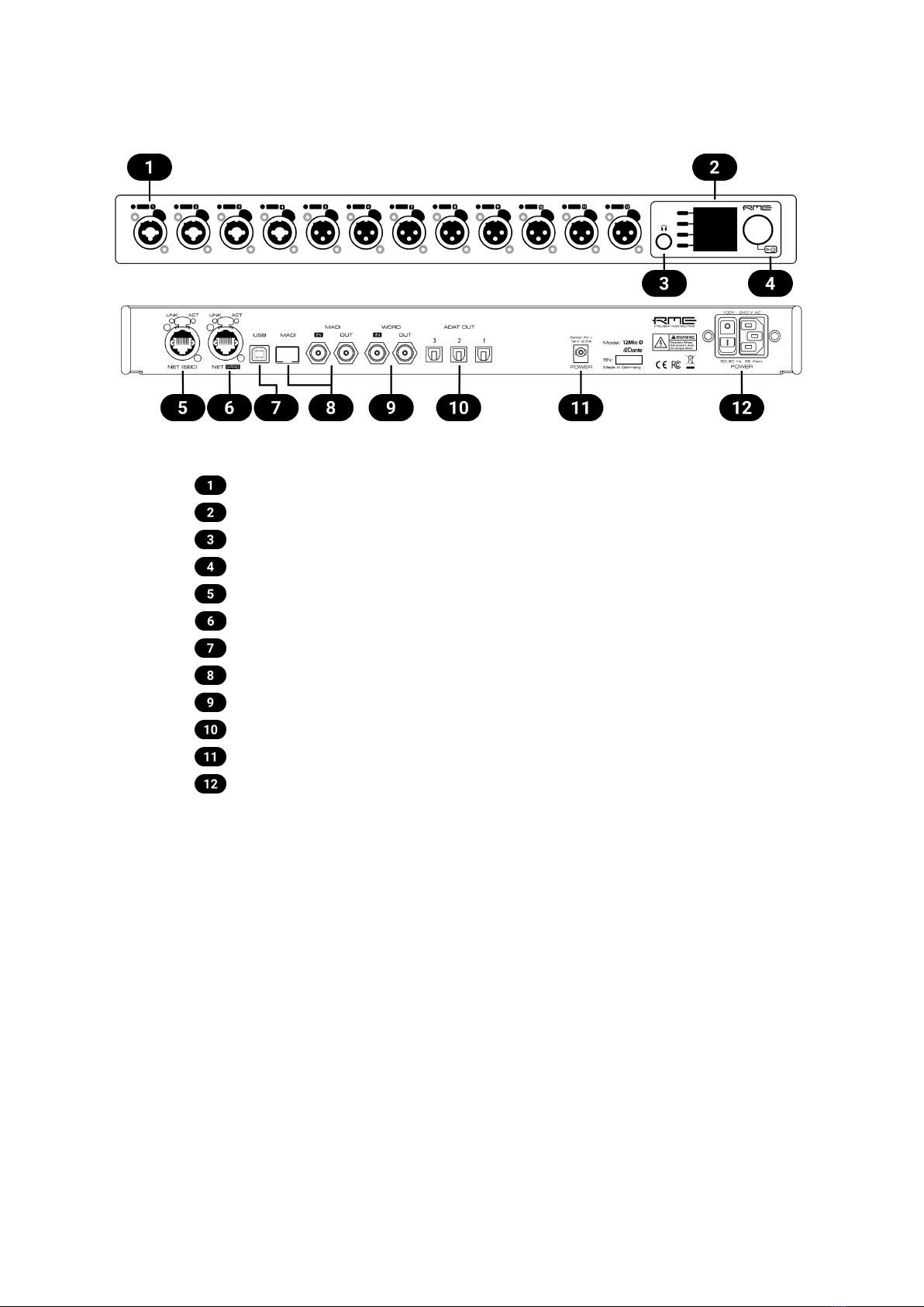
Section 3.6, “Analog Input Connectors”
Section 3.10, “Control Section”
Section 3.11, “Headphone Output”
Section 3.4, “Standby Switch”
Section 3.14, “Network Connection”, Secondary (SEC)
Section 3.14, “Network Connection”, Primary (PRI)
Section 3.16, “USB 2.0 Type B Jack”
Section 3.13, “MADI Coaxial and SFP”
Section 3.15, “Word Clock”
Section 3.17, “ADAT Outputs”
Section 3.12, “Power supply”
Section 3.12, “Power supply”
RME 12Mic-D User’s Guide
7| 3. Hardware

3.1. Hardware Specifications
RME 12Mic-D
EAN 42 6012336 341 3
Dimensions 440 x 44 x 243 mm (17.3 x 1.7 x 9.6 inches)
Weight 2.8 kg (6.2 lbs)
Package 560 x 315 x 115 mm (22.1 x 12.4 x 4.5 inches)
Conformity CE, FCC, WEEE, RoHS
Power supply internal 36 W 100-240 V AC
external 12 V d.c. 2.5 A (PS2) optional
Power consumption typ. 20 W, standby 0.5W
3.2. Package Contents
The package of the 12Mic-D contains the following items:
•12Mic-D
•two rack mount brackets
•four screws for rack mount brackets
•one power cord
•one Cat5e network cable
•printed manual
If any item is missing from a factory-sealed package, please contact your support
immediately.
3.3. Power On
The 12Mic-D has a power switch at the AC inlet and a standby switch at the front.
Perform the following steps to power on the 12Mic-D:
1. Ensure that one of the power inlets is properly connected to a power source.
2. When using the AC inlet, toggle the mains switch at the back of the device to position I(down). The
power indicator will light up in red (Standby) or white (On). This depends on the state of the device
before it was disconnected from a power source.
3. If the device is in standby mode, hold the encoder for two seconds to boot the device.
The 12Mic-D features a dark mode which deactivates some or all lights of the front panel.
This can be used to let the device appear powered off when it is in fact powered on. A short
push on the encoder or any button deactivates this mode temporarily.
RME 12Mic-D User’s Guide
3.1. Hardware Specifications | 8

3.4. Standby Switch
The front panel encoder acts as a standby switch. While in standby mode, the device is completely
powered down except for a red LED. No signals are processed or passed on.
Possible actions:
•When the device is in standby mode, pushing the encoder for two seconds will boot the device.
•When the device is powered on, push and hold the encoder for several seconds in order to power
down the device. A red progress bar is shown while the encoder is pushed.
3.5. Standby Indicator
The following illumination patterns are possible:
No illumination
•There is no power at either of the two power inlets.
•The power switch at the rear of the device is set to 'Off'.
•Dark mode has been activated.
Permanent red illumination
•The device is powered off but is receiving power at either one of the power inlets.
Permanent white illumination
•The device is powered on and all systems are working without warning.
Alternating red/white illumination
•Something is not working properly. This is triggered when one of the four display
sections: STATE, INPUT, OUTPUT, or CLOCK signals a warning.
RME 12Mic-D User’s Guide
9| 3.4. Standby Switch

3.6. Analog Input Connectors
XLR/TRS combo jacks 1-4
On the front of the device, four combined XLR/TRS inputs labeled "1" to "4" can be used for microphone,
line and instrument signals. Phantom power (48 V) for microphones can be activated on each XLR input,
high impedance ("Hi-Z") can be activated when using unbalanced TS connectors. Both XLR and TRS
jacks accept balanced signals and maintain full symmetry internally all the way to the A/D converter.
Phantom power is not applied at the TRS inputs.
XLR inputs 5-12
Eight additional XLR inputs labeled "5" to "12" can be used for microphone and line level signals. The
internal circuits are identical to the first four channels in XLR mode, with a fully symmetrical design.
When using unbalanced XLR, be sure to connect pin 3 (negative/"cold") to pin 1 (ground), to
avoid noise from the unconnected pin 3 input.
3.6.1. Analog Input Specifications
XLR In 1-12
•Input: XLR, electronically balanced
•Input impedance: 3.4 kOhm
•Gain range: 75 dB, 1 dB steps
•Resolution AD: 24 bit
•Frequency response @ 44.1 kHz, -0.1 dB: 8 Hz – 20.8 kHz
•Frequency response @ 96 kHz, -0.5 dB: 4 Hz – 29.2[1]
•Frequency response @ 192 kHz, -1 dB: 3 Hz – 43.7[1]
•THD @ 30 dB gain: < -110 dB, < 0.00032 %
•THD+N @ 30 dB gain: < -104 dB, < 0.00063 %
•Channel separation: > 110 dB
•Signal to Noise ratio (SNR): > 117 dB RMS unweighted, > 120 dB(A)
•Equivalent Input Noise (EIN), 30 dB Gain: 123 dB RMS unweighted, 125.5 dB(A) @ 150 Ohm
•Maximum input level, Gain 0 dB: +18 dBu
•Maximum input level, Gain 75 dB: -57 dBu
[1] optimized impulse response filter, see Section 3.7, “Frequency and Impulse Response”
TRS In 1-4
As above, but:
•Signal to Noise ratio (SNR): 115 dB RMS unweighted, 118 dBA
•TRS jack, balanced
•Gain range: 42 dB, 1 dB steps
•Maximum input level, Gain 8 dB: +20 dBu
•Maximum input level, Gain 50 dB: -22 dBu
RME 12Mic-D User’s Guide
3.6. Analog Input Connectors | 10

•Switchable high impedance (unbalanced TS): 1 MOhm
3.7. Frequency and Impulse Response
The A/D converters of the 12Mic-D are optimized for extremely low latencies (Short Delay IIR filters). At
single speed, the conversion prioritizes frequency response to ensure linear conversion across the entire
frequency band.
At double and quad speed (88.2 kHz and higher), the conversion has been optimized to deliver a near-
perfect impulse response. This is achieved by allowing a lower cutoff frequency and a slower roll-off of
the anti-aliasing filter. It shifts from around 44 kHz to 25 kHz at 96 kHz (84 kHz to 32 kHz at 192 kHz)
and attenuates higher signals less steeply. The resulting impulse response shows significantly less
ringing artifacts than steep filters at at a higher cutoff frequency. Since even the lower cutoff frequencies
are located well above the audible range, the advantage of the improved impulse response outweighs the
benefit of a higher cutoff frequency.
If the 12Mic-D is used for scientific research (ultrasonic signals) with measurement
microphones that maintain a linear frequency response above 25 kHz, please contact your
support for a custom solution.
3.8. Analog Input LEDs with Integrated Metering
Each analog input is accompanied by an LED. Shades of green, yellow, and
red represent the current level for each channel. Additionally, each LED shows
the active state of phantom power (yellow), active TRS input (white), active
High-Z impedance on TS (blue), and participation in a gain group (green) while
pressing the corresponding quick select buttons.
3.9. LED Meters Color and Intensity Reference
The following table describes the signal level represented by the backlight color. Each value corresponds
to full scale, which is equivalent to the reference level of the corresponding input.
Color Color name dBFS
Green -54 (barely visible in low light)
-40 (barely visible in daylight)
-20 (bright green)
Yellow -5 (strong yellow)
Orange -4
Red -1
Red flashing fast 0 (at least three consecutive samples)
RME 12Mic-D User’s Guide
11 | 3.7. Frequency and Impulse Response

3.10. Control Section
Section 3.8, “Analog Input LEDs with Integrated Metering”
Section 8.1.1, “Analog Input User Interfaces”
Display buttons
Toggle P48/Hi-Z/TRS
Display
Section 3.6, “Analog Input Connectors”
Section 3.11, “Headphone Output”
Phones output with routing
Input tab with warning
Section 3.4, “Standby Switch”
Encoder
The 12Mic-D can be configured at the device. To do so, the TFT display shows a menu. The adjacent
encoder knob and buttons are used to navigate and change settings. In addition, each input channel has
a dedicated button to access its controls.
The encoder can be pushed in order to activate an item,
and rotated left and right in order to select an item.
If the device is powered on but the display shows no content, dark mode is active. Rotate
the encoder to temporarily bypass this mode and show the display.
RME 12Mic-D User’s Guide
3.10. Control Section | 12

3.11. Headphone Output
The 12Mic-D features a stereo headphone output, 1/4" (6.3mm) TRS on the front panel. It can also
function as a dual mono unbalanced output (13 dBu) and as a mono balanced line level output (19 dBu).
Any digital or analog input signal can be monitored.
Always use balanced TRS connectors at this output.
3.11.1. Analog Output Specifications
Phones 1/2:
•Resolution: 24 Bit
•Noise (DR): 115 dB RMS unweighted, 118 dBA
•Frequency response @ 44.1 kHz, -0.5 dB: 9 Hz – 22 kHz
•Frequency response @ 96 kHz, -0.5 dB: 9 Hz – 45 kHz
•Frequency response @ 192 kHz, -1 dB: 8 Hz - 75 kHz
•THD+N: < -100 dB, < 0.001 %
•Channel separation: > 110 dB
•Output: 6.3 mm TRS stereo (unbalanced) or mono (balanced) jack
•Maximum output level at 0 dBFS: +13 dBu (unbalanced), +19 dBu (balanced)
•Output impedance: 100 Ω
RME 12Mic-D User’s Guide
13 | 3.11. Headphone Output
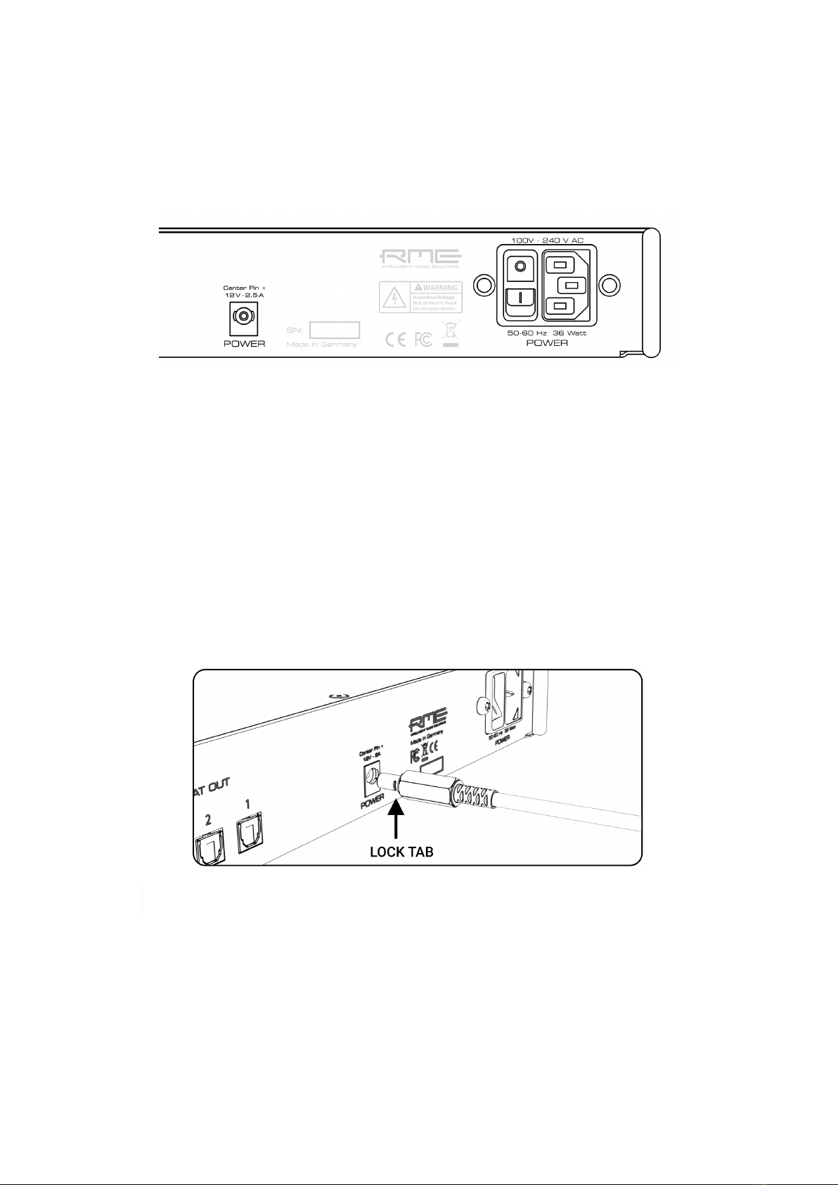
3.12. Power supply
The 12Mic-D has an internal power supply (PSU) that is connected via an IEC C14 inlet labeled "PSU" at
the rear of the device. It is a high performance switch mode power supply that accepts 100V to 240V AC.
It is short-circuit-proof, has an integrated line-filter, is fully regulated against voltage fluctuations, and
suppresses mains interference.
The power switch next to the inlet internally disconnects the line and neutral connection to the internal
power supply. Ground will remain connected.
12 V DC inlet
An optional external power supply can be connected instead of - or in addition to - the internal power
supply. Redundancy is established when both inlets are connected to a power source. Additionally, both
inlets are internally monitored. The 12Mic-D can warn when one of the inlets receives no power.
The power supply must be capable of delivering 2.5 A at 12 V DC and connect with a type A (IEC 60130-
10) plug (5.5 mm outer diameter, 2.1 mm inner diameter, positive polarity, optional lock tab).
Insert the connector fully with the lock tabs facing sideways, then gently turn 30 degrees clockwise to
secure the connector in place. Reverse this process to unlock and unplug the connector.
Do not push and turn the connector at the same time as this may damage the DC socket.
RME 12Mic-D User’s Guide
3.12. Power supply | 14

3.13. MADI Coaxial and SFP
The rear of the 12Mic-D features coaxial and SFP MADI (AES10-2003) I/O.
Each input receives up to 64 audio channels. Auto Input (see Section 8.2.2, “Connecting Two Identical
MADI Signals for Redundancy”) can be activated to treat both inputs as one.
The coaxial BNC connector accepts coaxial cables with 75 Ω impedance.
The "small form-factor pluggable" connector (SFP) accepts 125 MBit/s transceivers with LC connectors,
1310mm wavelength and multi-mode (MM) or single-mode (SM) cable support. These must be
purchased separately (see Section 4, “Accessories”).
An SFP module has indicators to distinguish transmitter (▼) and receiver (▲). It can be inserted and
removed while the device is powered on (hot plugging). Any plugged in connector must be removed
before unlocking the SFP. Unlock and remove by pulling its integrated wire latch outward.
The wire latch of the SFP module is color coded. Black stands for the most common
multimode module, blue stands for single mode which allows longer distance
transmissions. It is possible, but not reliable to connect single mode transceivers with
multi mode transceivers. Avoid this by always confirming that connected devices match
the specification of the fiber optic cable.
On the device, the characteristics and state of the signal at either input can be inspected in the INPUT
section.
The presence or loss of a signal at either port is indicated on the standby screen and main menu if
•the input port is selected as clock master, or
•its audio channels are routed in the OUTPUT section.
When using the web remote, the characteristics and state of the signal at either input can be inspected in
the CLOCK section.
RME 12Mic-D User’s Guide
15 | 3.13. MADI Coaxial and SFP
Table of contents
Other RME Audio Amplifier manuals


