RMS 1B230 User manual

1B230 User Guide
Two Shot Auto Reclose Relay
relay monitoring systems pty ltd
Advanced Protection Devices
User Guide
Test Manual

1B230
User Guide
About This Manual
This User Guide covers all1B230 relays manufactured from May 2003. Earlier relays do not
necessarily incorporate all the features described. Our policy of continuous may means that extra
features & functionality may have been added.
The 1B230 User Guide is designed as a generic document to describe the common operating
parameters for all relays built on this platform. Some relay applications are described but for specific
model information the individual “K” number Product / Test manuals should be consulted.
The copyright and other intellectual property rights in this document, and in any model or article produced
from it (and including any Registered or unregistered design rights) are the property of Relay Monitoring
Systems Pty Ltd. No part of this document shall be reproduced or modified or stored in another form, in any
data retrieval system, without the permission of Relay Monitoring Systems Pty Ltd, nor shall any model or
article be reproduced from this document without consent from Relay Monitoring Systems Pty Ltd.
While the information and guidance given in this document is believed to be correct, no liability shall be
accepted for any loss or damage caused by any error or omission, whether such error or omission is the
result of negligence or any other cause. Any and all such liability is disclaimed.
Contact Us
©Relay Monitoring Systems Pty Ltd 2001-2003
6 Anzed Court • Mulgrave 3170 • AUSTRALIA
Phone 61 3 9561 0266 • Fax 61 3 9561 0277
Email [email protected] • Web www.rmspl.com.au
To download a PDF version of this guide:
http://www.rmspl.com.au/userguide/1b230_user_guide.pdf
To download the model specific Test Manual:
http://www.rmspl.com.au/search.asp

How this guide is organised
This guide is divided into five parts:
Part 1 Overview
About this Manual
Contents
Test Manual
Mechanical Configuration
Part 2 Technical Bulletin
Part 3 Description of Operation
Function Selection
Operating Logic
Flow charts
Part 4 Installation
Handling of Electronic Equipment
Safety
Unpacking
Accessories
Storage & Handling
Equipment Operating Conditions
Relay Dimensions & Other Mounting Accessories
Equipment Connections
Commissioning
Decommissioning & Disposal
Part 5 Maintenance
Mechanical Inspection
Test Intervals
Defect Report Form
Visit www.rmspl.com.au for the latest product information.
Due to RMS continuous product improvement policy this information is subject to change without notice. 1B230_Guide/Iss E/25/08/08

Test Manual
Part
1
This User Guide covers all 1B230 relay versions & describes the generic features & attributes
common across all versions.
Different relay versions are required to cater for varying customer requirements such as auxiliary
voltage range, I/O configuration, case style, relay functionality etc.
The product ordering code described in the Technical Bulletin is used to generate a unique
version of the relay specification & is called a type number. The type number takes the form
1B230Kxx where the Kxx is the “K” or version number.
Refer to: www.rmspl.com.au/handbook/parta3.pdf
for a complete description of the RMS “K” number system.
Each 1B230 version has a specific Test Manual which provides details on the unique attributes of
the relay. Each Test Manual includes the following information:
•Test Certificate
•Specific technical variations from the standard model if applicable
•Test & calibration record
•Wiring diagram
A Test Manual is provided with each relay shipped.
If you require a copy of the Test Manual for an RMS product the following options are available:
•Check the RMS web site at: www.rmspl.com.au/search.asp
•RMS CD catalogue select: List all Product/Test Manuals under Technical Library
•Contact RMS or a representative & request a hard copy or PDF by email.
Visit www.rmspl.com.au for the latest product information.
Due to RMS continuous product improvement policy this information is subject to change without notice. 1B230_Guide/Iss E/25/08/08

Mechanical Configuration
Great care has been taken to design a rugged, cost effective & flexible mechanical solution for
the MATRIX range of RMS protection relays. The MATRIX range provides a compact draw out
case solution with M4 screw terminals:
•2M28 Size 2 with 28 terminals
•4M28 Size 4 with 28 terminals
•4M56 Size 4 with 56 terminals
Complete details & attributes for the M (MATRIX) cases & accessories may be found at:
http://www.rmspl.com.au/mseries.htm
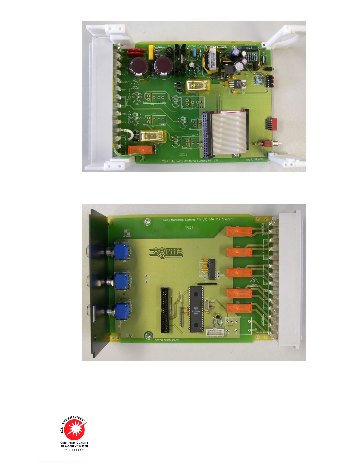
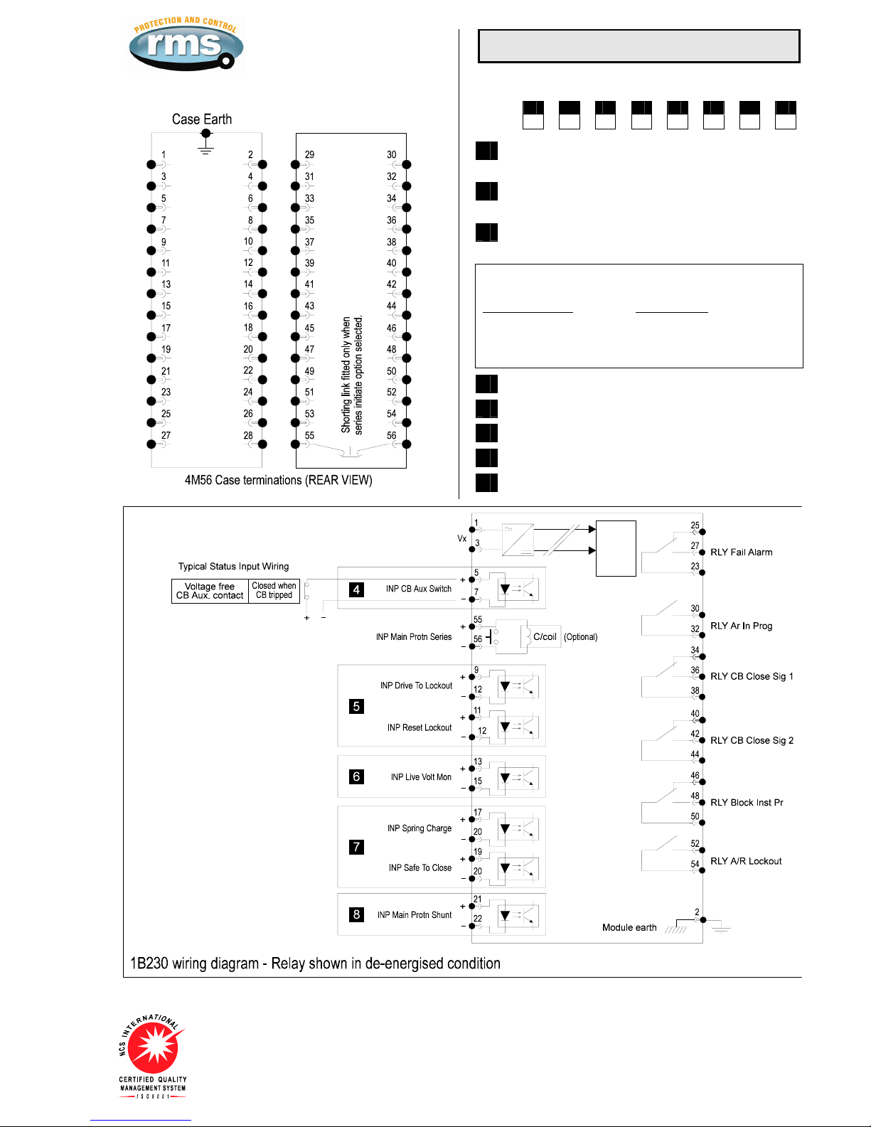
The 1B230 is configured in a 4M56 case & the following photographs depict the general
mechanical configuration. It should be noted that re-usable screw rivets are used to bind the
draw out relay module. A 1/16” hex key is required for disassembly.
1B230 Module viewed from top.
Visit www.rmspl.com.au for the latest product information.
Due to RMS continuous product improvement policy this information is subject to change without notice. 1B230_Guide/Iss E/25/08/08
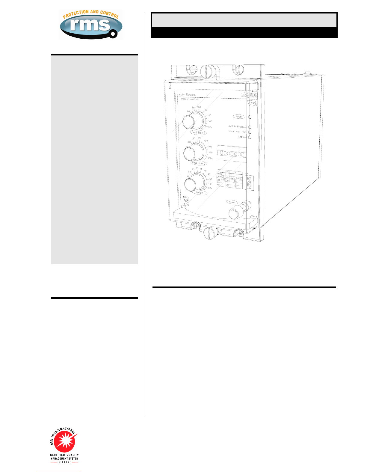
1B230 Primary PCB showing the switch mode power supply components at the top.
1B230 Secondary PCB showing time delay setting controls, output relays & CPU.
Visit www.rmspl.com.au for the latest product information.
Due to RMS continuous product improvement policy this information is subject to change without notice. 1B230_Guide/Iss E/25/08/08

Technical Bulletin
Part
2
The detailed technical attributes, functional description & performance specifications for the
1B230 are described in the attached Technical Bulletin. For the most up to date version go to:
www.rmspl.com.au/handbook/1b230.htm
For any specific attributes of a particular version refer to the Test Manual for that type (K)
number.
The order of precedence for technical information is as follows:
•Test Manual
•Technical Bulletin
•User Guide
Visit www.rmspl.com.au for the latest product information.
Due to RMS continuous product improvement policy this information is subject to change without notice. 1B230_Guide/Iss E/25/08/08
Visit www.rmspl.com.au for the latest product information.
Due to RMS continuous product improvement policy this information is subject to change without notice. 1B230/Issue F/15/08/07/1/5
Features
Single or double shot reclose
with selectable auto reset
mode
Shunt initiate input
Optional series initiate input
Safe to reclose input
Line voltage interlock
CB reclose spring status input
to defer auto reclose pulse until
fully charged
Lockout LED indication
Drive to lockout input
Remote reset input
Reclose in progress LED
Instantaneous protection inhibit
output & LED indication
Wide auxiliary supply range
with fail alarm contact
Independently adjustable dead
time delay per shot
Common adjustable reclaim
time delay
Optional reclose counter
Simple rugged design
Size 4M draw out case
Application
Operating records for overhead power
lines reveal that most faults are of a
transient nature (e.g. lightning induced) &
that service interruptions may be
minimized by use of automatic reclosing of
circuit breakers.
An automatic reclosure of the circuit
breaker, after the fault clears, provides
improved service continuity & system
stability.
The 1B230 Series Reclose Relay provides
for single or double shot automatic
reclosing of circuit breakers, following
interruption of supply due to a fault in the
system.
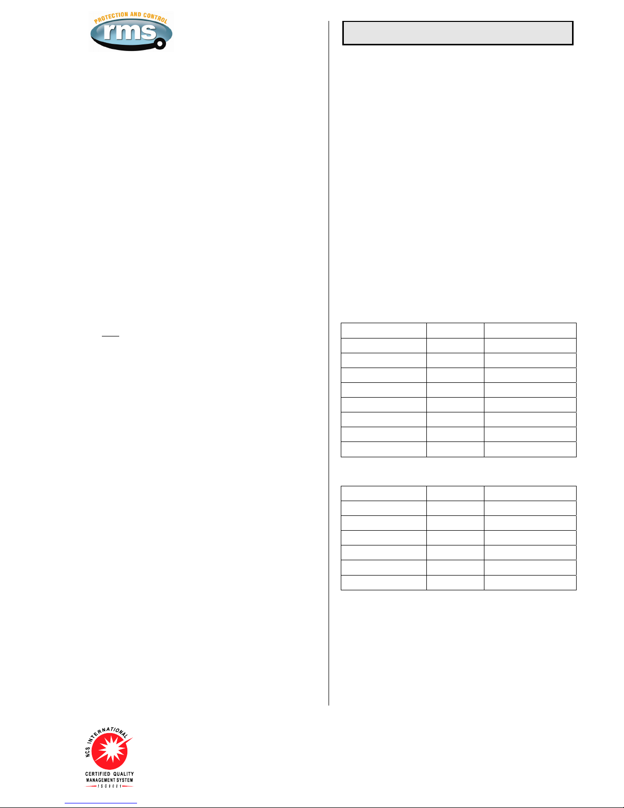
Technical Bulletin 1B230
Single or Double Shot Auto Reclose Relay
1B230 depicted in a 4M28 case
Operation Made in Australia
The 1B230 auto reclose relay provides up to two shot auto reclose control for distribution
and transmission systems. Dead times for both shots (reclose attempts) are independently
adjustable.
An auto reclose cycle is initiated by operation of a protective relay (INP Main Protn),
provided the circuit breaker is closed until the instant of protection operation.
Dead time 1or 2 start when the circuit breaker has tripped (INP CB Aux Switch) and the
protection has reset.
At the end of the dead time, a CB close signal is given (output RLY CB Close Sig),
provided input signals are present indicating that system conditions are suitable (INP Safe
To Close), and the circuit breaker closing spring, or other energy source, is fully charged
(INP Spring Charge).
The safe to close signal is taken from a contact on a separate voltage monitor or
synchronism check relay, and the spring charged signal is taken from an auxiliary switch
contact on the circuit breaker. The CB close signal is cut off when the circuit breaker
closes.
Once the output pulse to close the circuit breaker is completed, the reclaim time starts. If
the circuit breaker remains closed until the reclaim timer times out, the 1B230 resets if in
auto mode or goes to lockout.
However if the protection operates again & the circuit breaker trips before the reclaim time
has elapsed, the 1B230 either advances to the next shot in the programmed auto reclose
cycle, of, if all programmed reclose attempts have been made, goes to lockout.
Visit www.rmspl.com.au for the latest product information.
Due to RMS continuous product improvement policy this information is subject to change without notice. 1B230/Issue F/15/08/07/2/5
BLOCK INSTANTANEOUS TRIPS OUTPUT
A Block Instantaneous Trips output (RLY Block Inst Pr) can be
arranged to block the trip function of non-discriminating
protection, such as low set instantaneous overcurrent or earth
fault protection, or distance protection operating with Zone 1
extension. This function is used to ensure that the final trip to
lock out for a persistent fault is made by discriminating protection
& can be set at the front panel to operate after the first trip, after
the second trip or to OFF (Function disabled).
The output relay is normally reset and to operates (contact
closes) to block non-discriminating protection.
This is suitable for most modern protective relays such as
Ohmega & Argus.
CIRCUIT BREAKER AUXILIARY CONTACT
An auxiliary contact on the circuit breaker (Closed when the CB is
tripped) is required to monitor the operation of the CB using the
INP CB Aux Switch.
LINE VOLTAGE INTERLOCK INPUT
Line status information is derived from input INP Line Volt Mon.
This feature inserts additional checks in the auto reclose initiation
and dead time start logic, such that an auto reclose cycle can only
be initiated if the line was live until immediately before the
protective relay operation, and the dead time cannot start until the
line has gone dead.
Front panel switch selection of Live Line IN or OUT.
CB RECLOSE SPRING STATUS INPUT
Application of a control voltage to the INP Spring Charge input
will defer the CB reclose output pulse (RLY CB Close Sig) until
the signal is removed. This function is used to ensure that the CB
will not receive a reclose pulse until after the reclose spring is
fully charged.
The spring charged signal is taken from an auxiliary switch
contact on the circuit breaker.
If the INP Spring Charge input defers the CB reclose output
pulse for 60s the 1B230 will go to lockout.
MAIN PROTECTION INTERFACE
Two input types are provided to interface with the main protection
to initiate the reclose cycle:
1. Shunt initiate Voltage input to INP Main Protn Shunt
Pulse Length >40 m Sec
2. Series initiate Current input to INP Main Protn Series
(optional) Current >1.2 Amp DC
Pulse Length >40 m Sec
Resistance <0.5 ohm
SAFE TO CLOSE INPUT
A control voltage to the INP Safe To Close input must be applied
before a CB close pulse can be output.
If the CB reclose output pulse is delayed for 60s by the INP Safe
to Close input is not being applied, the 1B230 will go to lockout.
DRIVE TO LOCKOUT INPUT
Application of a voltage pulse to the INP Drive To Lockout input
will drive the 1B230 to the lockout condition.
Function Details
RESET RELAY FROM LOCKOUT
The 1B230 may be reset from the lockout condition in 3 ways:
1. Application of a voltage pulse to the INP Reset Lockout input;
2. Pressing the front panel reset button;
3. Interruption of the auxiliary supply for >10s.
RECLOSE OPERATION
Front panel switch selection of Single (1) or double Shot (2)
Front panel switch selection of Lockout (L) or Auto Reset (A)
The contact closure output pulse (RLY CB Close Sig) is of 2
second duration.
TIME DELAY SETTING RANGES
Dead Time 1 (Reclose 1): 5 to 180s
Dead Time 2 (Reclose 1): 5 to 180s
Reclaim Time Delay: 5 to 60s
TIMING ACCURACY
Repeat ± 1% of setting
Setting ± 2% of max. setting
OPERATION INDICATORS
LED indication of relay healthy
LED indication of reclose in progress - Initiation to reset or lockout
LED indication of block non discriminating protection
LED indication of relay in lockout condition
OPTIONAL COUNTER (Cumulative)
7 Digit (non reset).
STATUS INPUT SUMMARY
Description Signal Comments
INP CB Aux Switch Steady state Apply volts
INP Main Protn Shunt Pulse Apply volts
INP Main Protn Series Pulse Apply current (Optional)
INP Safe To Close Steady state Apply volts
INP Spring Charge Steady state Apply volts
INP Drive To Lockout Pulse Apply volts
INP Reset Lockout Pulse Apply volts
INP Line Volt Mon Steady State Use Live Line In switch
RELAY OUTPUT SUMMARY
Description Signal Comments
RLY A/R In Prog Steady state 1 C/O follows LED
RLY CB Close Sig 1 2s pulse 1 C/O
RLY CB Close Sig 2 2s pulse 1 C/O
RLY Block Inst Pr Steady state 1 C/O
RLY A/R Lockout Steady state 1 C/O
RLY Fail alarm Steady state 1 C/O P/U when healthy
Visit www.rmspl.com.au for the latest product information.
Due to RMS continuous product improvement policy this information is subject to change without notice. 1B230/Issue F/15/08/07/3/5
AUXILIARY SUPPLY BURDEN (At 110V DC)
Less than 5W independent of range with output relays picked up.
AUXILIARY SUPPLY
20-70V AC/DC switchmode supply or
40-275V AC / 40-300V DC switchmode supply
Burden: Less than 7 watts during timing
Inputs:
A high efficiency switchmode power supply is incorporated which
provides a low burden to the auxiliary supply and operates over
the range 75 to 140V AC & 70 to 150V DC.
Input Transients:
Withstands multiple high energy transients & ring waves in
accordance with IEEE28 - ANSI C26.1 Cat. II, accordingly:
0.5uS 100KHz 6KV O/C, 500A S/C, 4J
1.2/50uS 6Kv O/C
8/20uS 3KA S/C, 80J clamped at 1,000V
Mains conducted EMI within limits specified by AS 3548 Class B.
Isolation:
The inputs are isolated from the outputs in accordance with AS
3260 Class II Limited Current Circuitry, accordingly:
Withstand voltage of 2.5Kv RMS 50Hz for one minute
Creepage & clearance distance greater than 4mm
Output leakage current less than 0.25A to earth
Power Supply Alarm Relay:
A normally closed contact rated at 10A 250V AC & isolated as per
AS 3260 is energized when both the auxiliary supply & internal
24V DC rail is within acceptable limits. The relay faulty alarm
output will be set if the incoming supply or switch mode circuit
fails.
Output Protection:
Outputs will withstand continuous short circuit. Output regulators
& switching control regulator are thermally protected.
SCHRACK OUTPUT CONTACT RATINGS
Make & carry
30A AC or DC (Limits L/R=40ms & 300V max.) for 0.2s
20A AC or DC (Limits L/R=40ms & 300V max.) for 0.5s
5A AC or DC continuously
Break (Limits 5A & 300V max.)
1,250VA AC resistive
250VA at 0.4PF AC inductive
75W DC resistive
30W DC inductive L/R = 40ms
50W DC inductive L/R = 10ms
Minimum recommended load
0.5W, 10mA or 5V minimum.
Relay Ratings
AMBIENT OPERATING TEMPERATURE RANGE
-5 to 55 degrees C.
NOISE IMMUNITY
Withstands the high frequency interference test detailed in IEC
255-22-1.
INSULATION WITHSTAND in accordance with IEC 255-5:
2KV RMS & 1.2/50 5KV impulse between:
♦all input terminals & frame
♦all output terminals & frame
♦all input & output terminals
♦each input group
♦each output group
Across open contacts: 1KV RMS
ELECTROSTATIC DISCHARGE
EN61000-4-2:1995 8KV Level 3
FAST TRANSIENT DISTURBANCE
EN61000-4-4:1995 4KV Level 4
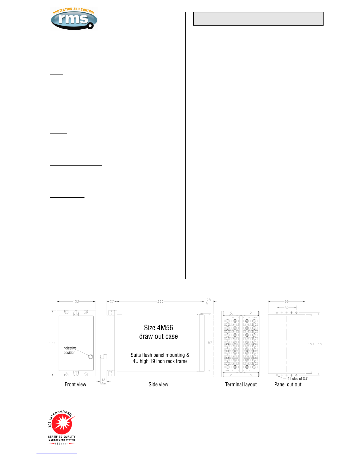
CASE
Size 4 draw out
56 M4 screw terminals
Flush panel mount or 4U high 1/4 width 19 inch rack mount
IP51 rating
ACCESSORIES SUPPLIED WITH EACH RELAY
1 x M4 self threading mounting screw kit P/N 290-406-151
2 x M4 terminal screw kit (28 per kit) P/N 290-407-153
1 x Product Test Manual
SHIPPING DETAILS
Each relay is supplied individually packed in pre formed
cardboard cartons with internal moulded polystyrene former.
Weight: 3Kg
Size: 370(L) x 240(W) x 145(D)mm - Size 4 case
For large shipment individual cartons are packed in sturdy cardboard
pallet boxes & surrounded by loose fill to absorb vibration & shock
during transit.
Visit www.rmspl.com.au for the latest product information.
Due to RMS continuous product improvement policy this information is subject to change without notice. 1B230/Issue F/15/08/07/4/5
Ordering Information
Generate the required ordering code as follows:
e.g. 1B230 BAAHACCD
1 2 3 4 5 6 7 8
1B230
1 AUXILIARY SUPPLY RANGE
A 20-70V DC B 40-275V AC / 40-300V DC
2 COUNTER
A Not required B Required
3 SERIES INITIATE INPUT
A Not required B Required
Select for status input codes 4 – 8
A Not required
Opto-isolated input Relay coil input
B 24-80V AC/DC E 12V DC
C 75-150V AC/DC F 24V DC
D 150-300V AC/DC G 48V DC
H 110V DC
4 STATUS INPUT INP CB Aux Switch
5 STATUS INPUT INP Drive To Lockout / INP Reset Lockout
6 STATUS INPUT INP Line Volt Mon
7 STATUS INPUT INP Spring Charge / INP Safe To Close
8 STATUS INPUT INP Main Protn Shunt

Visit www.rmspl.com.au for the latest product information.
Due to RMS continuous product improvement policy this information is subject to change without notice. 1B230/Issue F/15/08/07/5/5
Timing Sequence

Description of Operation
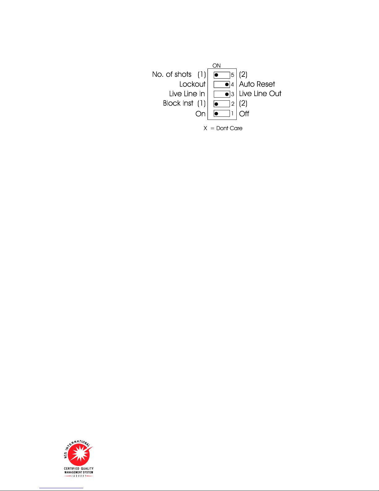
The 1B230 function is determined by the setting combination of five (5) switches located on the front
panel. The following sections provide a description of each operating combination & a logic flow chart.
The function provided by the Live Line switch is to ensure that the Line voltage is zero before a
reclose can be attempted. Switching this to the “Out” position removes this safety feature. Some relay
versions do not have the hardware to support this feature & switch 3 position is designated “Not Used”
which has the same effect as “Live Line Out”.
The following table summarizes all of the switch setting combinations & provides a reference to the
elevant manual section:r
Switch 1 Switch 2 Switch 3 Switch 4 Switch 5
Number of Shots Block Instantaneous
Section 1 2
Lockout
Auto
Reset Live Line
In Live Line
Out 1 2 On Off
3.1 x x x x
3.2 x x x x
3.3 x x x x x
3.4 x x x x x
3.5 x x x x
3.6 x x x x
3.7 x x x x x
3.8 x x x x x
3.9 x x x x x
3.10 x x x x x
3.11 x x x x
3.12 x x x x
3.13 x x x x x
3.14 x x x x x
3.15 x x x x
3.16 x x x x
3.17 x x x x x
3.18 x x x x x
3.19 x x x x x
3.20 x x x x x
Part
3
Visit www.rmspl.com.au for the latest product information.
Due to RMS continuous product improvement policy this information is subject to change without notice. 1B230_Guide/Iss E/25/08/08
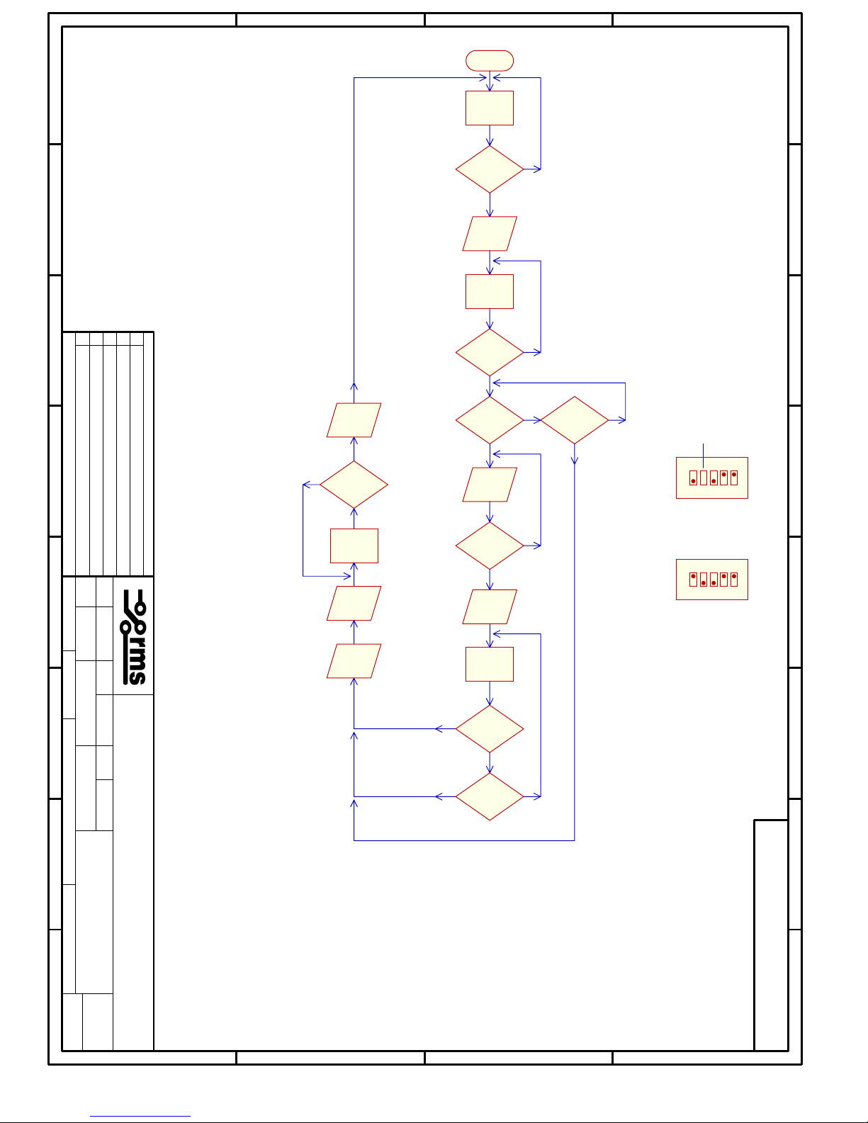
3.1 Single Shot, Auto Reset, Live Line Out, Block Instantaneous OFF
1. Once the breaker has tripped and the Protection Trip Contact has closed the A/R in
progress LED will flash and the A/R contact will close, the relay will wait for the setting of
Dead Time 1 to expire, it will then issue a reclose output pulse, the counter will increment
one count and the A/R in progress LED will become steady.
2. If the breaker closes and the protection opens the relay will reset after the Reclaim time
expires and will be ready for the next breaker operation.
3. If however after issuing the reclose pulse the Protection Trip Contact is still present the relay
will drive directly to Lockout. If the Protection Trip Contact has reset but the Circuit Breaker
has not, the relay will wait for the Reclaim time to expire before it goes to lockout.
4. The Lockout indication and contact has to be reset from the front panel of the relay.
5. Refer to flowchart 1B230B-1-100 for the sequence of operation.
Visit www.rmspl.com.au for the latest product information.
Due to RMS continuous product improvement policy this information is subject to change without notice. 1B230_Guide/Iss E/25/08/08
12345678
12345678
A
B
C
D
A
B
C
D
DATE: TIME:
FILE NAME:
Amendments
DRAWN DATE D/O
CHECK DATE APPV
CHECK DATE
SCALE: CURRENT CNSHEET:
16-Oct-2003
1B230B
FLOWCHART
ISSUE
DRAWING NUMBER
SHEET: OF: ISSUE DATE
N.I.1
D.W.B
1B230B-1-100
1
1B230B-1-100
16-Oct-2003 10:07:46
D:\THE_CHIP\RMS\1B230\DOCO\Flowcharts\1B230B-1-100.Sch
V1.00
PROTECTION
AND AUX CB
TRIPPED
NO
YES
DEAD TIME
EXPIRED NO
YES
DEAD TIME
PULSE TIME
EXPIRED NO
YES
ISSUE
CB CLOSE
NO
RECLAIM TIME
PROTECTION
TRIPPED
NO
YES
STATE
RESET LOCKOUT
NO
YES
YES
AUX CB
RESET
NO
POWER UP
RESET STATE
WAIT FOR
WAIT FOR
LOCKOUT
ISSUE
PROGRESS
REMOVE
CB CLOSE
YES
ISSUE
LOCKOUT
REMOVE
LOCKOUT
54321
ON
54321
ON
DON'T CARE
SWITCH SETTINGS
1 SHOT, BLOCK INST OFF OR 2, AUTO LOCKOUT, LIVE LINE OUT
RECLAIMTIME
EXPIRED
SPRING CHARGED
& SAFE TO CLOSE
NO
YES
REMOVE
PROGRESS
WAIT TIME
EXPIRED NO
YES
REMOVE
PROGRESS
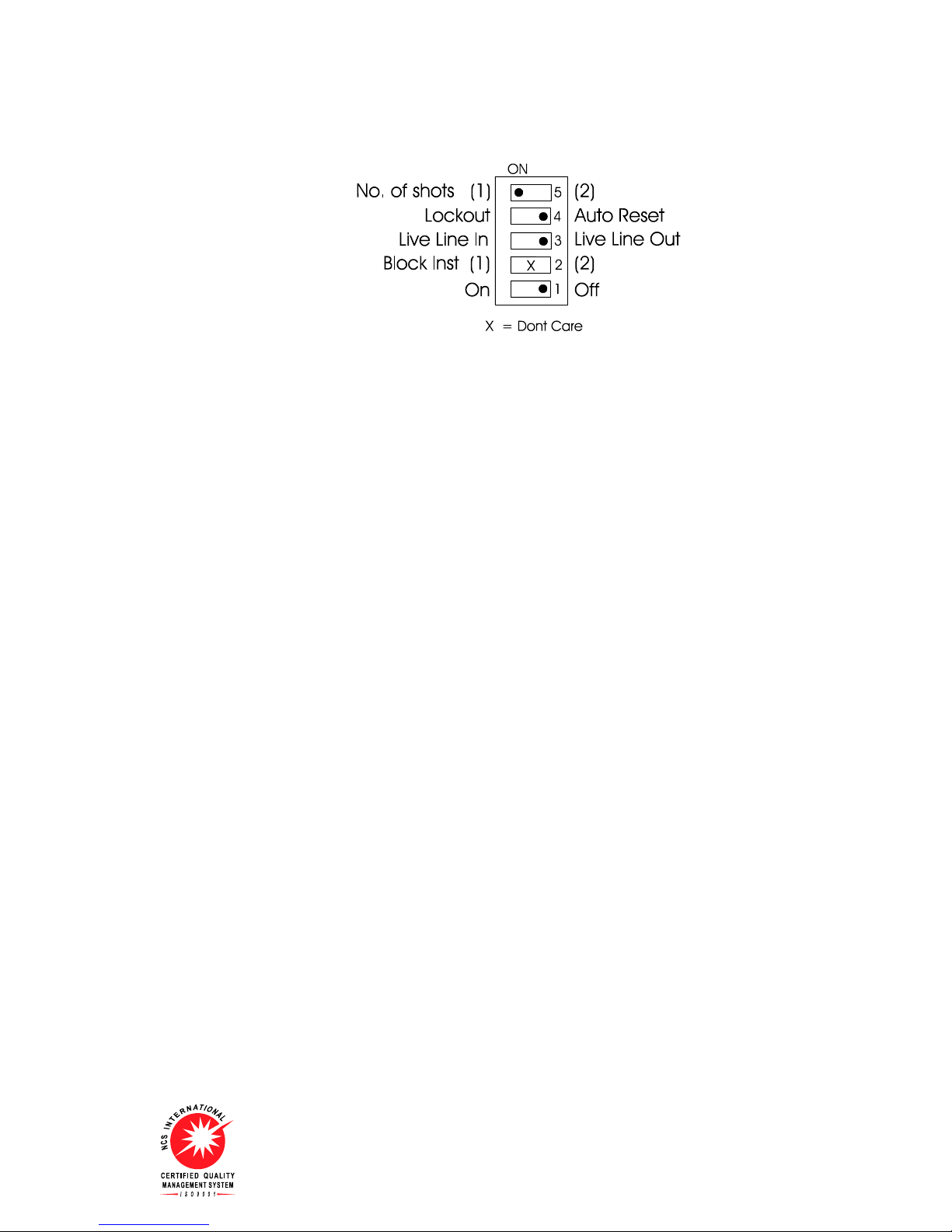
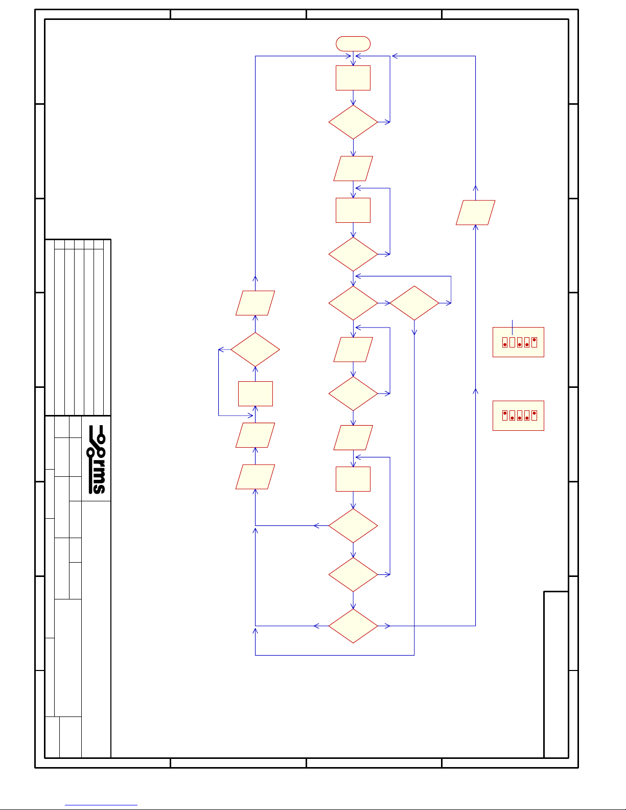
3.2 Single Shot, Lockout ON, Live Line Out, Block Instantaneous OFF
1. Once the breaker has tripped and the Protection Trip Contact has closed the A/R in
progress LED will flash and the A/R contact will close. The relay will wait for the setting of
Dead Time 1 to expire, it will then issue a reclose output pulse, the counter will increment
one count and the A/R in progress LED will become steady.
2. If the Circuit Breaker and the Protection Trip Contact opens the relay will wait for the Reclaim
time to expire and will then go to Lockout.
3. If after the Reclose pulse the Protection Trip Contact is still present the relay will go directly to
Lockout.
4. The Lockout indication and contact has to be reset from the front panel of the relay.
5. Refer to flowchart 1B230B-2-100 for the sequence of operation.
Visit www.rmspl.com.au for the latest product information.
Due to RMS continuous product improvement policy this information is subject to change without notice. 1B230_Guide/Iss E/25/08/08
12345678
12345678
A
B
C
D
A
B
C
D
DATE: TIME:
FILE NAME:
Amendments
DRAWN DATE D/O
CHECK DATE APPV
CHECK DATE
SCALE: CURRENT CNSHEET:
16-Oct-2003
1B230B
FLOWCHART
ISSUE
DRAWING NUMBER
SHEET: OF: ISSUE DATE
N.I.1
D.W.B
1B230B-2-100
1
1B230B-2-100
16-Oct-2003 10:13:00
D:\THE_CHIP\RMS\1B230\DOCO\Flowcharts\1B230B-2-100.Sch
V1.00
PROTECTION
AND AUX CB
TRIPPED
NO
YES
DEAD TIME
EXPIRED NO
YES
DEAD TIME
PULSE TIME
EXPIRED NO
YES
ISSUE
CB CLOSE
NO
RECLAIM TIME
PROTECTION
TRIPPED
NO
YES
STATE
RESET LOCKOUT
NO
YES
POWER UP
RESET STATE
WAIT FOR
WAIT FOR
LOCKOUT
ISSUE
PROGRESS
REMOVE
CB CLOSE
YES
ISSUE
LOCKOUT
REMOVE
LOCKOUT
ON
12345
ON
12345
DON'T CARE
SWITCH SETTINGS
1 SHOT, BLOCK INST off or 2, LOCKOUT ON, LIVE LINE OUT
RECLAIMTIME
EXPIRED
SPRING CHARGED
& SAFE TO CLOSE
NO
YES
REMOVE
PROGRESS
WAIT TIME
EXPIRED NO
YES

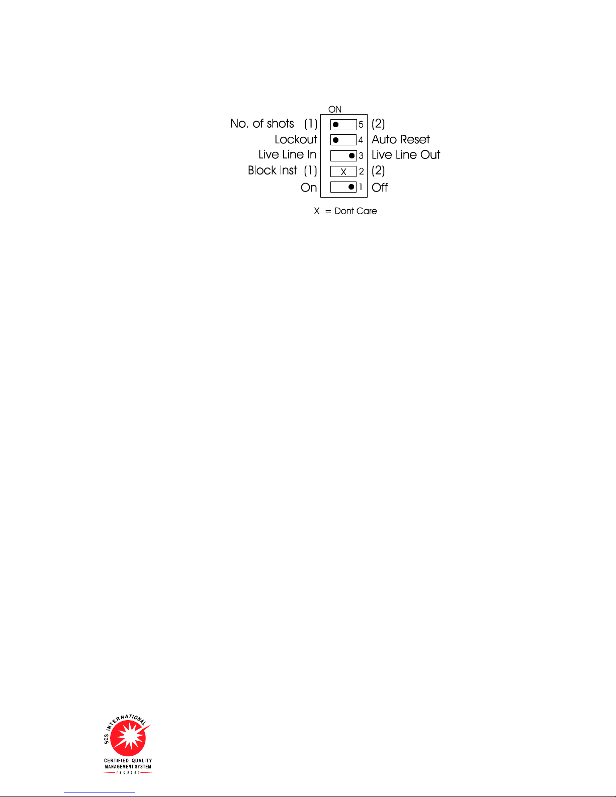
3.3 Single Shot, Lockout ON, Live Line Out, Block Instantaneous after 1st Trip
With the switch setting depicted above the relay will go through the following operations.
1. Once the breaker has tripped and the Protection trip contact has closed the A/R in
progress LED will flash and the A/R contact will close. The relay will wait for the setting of
Dead Time 1 to expire, it will then issue a reclose output pulse, the counter will increment
one count and the A/R in progress LED will become steady.
2. If the Protection Trip Contact is still closed after the reclose pulse, the Block Instantaneous
Protection contact will open, the LED will extinguish and the relay will go directly to Lockout.
3. If the Protection Trip Contact has opened the relay will wait for the Reclaim Time to expire
before removing the Block Instantaneous Protection contact and LED and driving to
Lockout.
4. The Lockout indication and contact has to be reset from the front panel of the relay.
5. Refer to flowchart 1B230B-3-100
Visit www.rmspl.com.au for the latest product information.
Due to RMS continuous product improvement policy this information is subject to change without notice. 1B230_Guide/Iss E/25/08/08

12345678
12345678
A
B
C
D
A
B
C
D
DATE: TIME:
FILE NAME:
Amendments
DRAWN DATE D/O
CHECK DATE APPV
CHECK DATE
SCALE: CURRENT CNSHEET:
16-Oct-2003
1B230B
FLOWCHART
ISSUE
DRAWING NUMBER
SHEET: OF: ISSUE DATE
N.I.1
D.W.B
1B230B-3-100
1
1B230B-3-100
16-Oct-2003 10:13:17
D:\THE_CHIP\RMS\1B230\DOCO\Flowcharts\1B230B-3-100.Sch
V1.00
PROTECTION
AND AUX CB
TRIPPED
NO
YES
DEAD TIME
EXPIRED NO
YES
DEAD TIME
PULSE TIME
EXPIRED NO
YES
ISSUE
CB CLOSE
NO
RECLAIM TIME
PROTECTION
TRIPPED
NO
YES
STATE
RESET LOCKOUT
NO
YES
POWER UP
RESET STATE
WAIT FOR
WAIT FOR
LOCKOUT
ISSUE
PROGRESS
REMOVE
CB CLOSE
YES
REMOVE
ISSUE
LOCKOUT
REMOVE
LOCKOUT
ON
12345
SWITCH SETTINGS
BLOCK
PROTECTION
AND BLOCK
PROTECTION
1 SHOT, BLOCK INST 1, LOCKOUT ON, LIVE LINE OUT
REMOVE
BLOCK
PROTECTION
RECLAIMTIME
EXPIRED
SPRING CHARGED
& SAFE TO CLOSE
NO
YES
REMOVE
PROGRESS
WAIT TIME
EXPIRED NO
YES
3.4 Single Shot, Auto Reset, Live Line Out, Block Instantaneous after 1st Trip
With the switch setting depicted above the relay will go through the following operations.
1. Once the breaker has tripped and the Protection trip contact has closed the Block
Instantaneous contact will pick up and the front panel LED will be lit, the A/R in progress LED
will flash and the A/R contact will close. The relay will wait for the setting of Dead Time 1 to
expire, it will then issue a reclose output pulse, the counter will increment one count and the
A/R in progress LED will become steady.
2. If the Protection Trip Contact and Circuit Breaker has closed the relay will wait for the Reclaim
time to expire then the Block Instantaneous Protection LED and contact will reset and the relay
will reset ready for the next operation.
3. If the Protection Trip Contact is still operated after the Reclose Pulse the relay will drive directly
to Lockout.
4. If after the Reclaim time has expired but the Circuit Breaker has not closed the Block
Instantaneous Protection LED and contact will reset and the relay will go to Lockout.
5. The Lockout indication and contact has to be reset from the front panel of the relay.
6. Refer to flowchart 1B230B-4-100
Visit www.rmspl.com.au for the latest product information.
Due to RMS continuous product improvement policy this information is subject to change without notice. 1B230_Guide/Iss E/25/08/08
Table of contents
Popular Other manuals by other brands

Minolta
Minolta Magicolor 3100 Series Maintenance Guide

K&K Sound
K&K Sound PURE 12-STRING product manual

Counter Assault
Counter Assault Pentagon user manual

ALBA-KRAPF
ALBA-KRAPF COLIBRI Assembly instructions

Panasonic
Panasonic TY-FB7SD operating instructions

Kathrein
Kathrein RRU4-RS4-E6 installation manual


