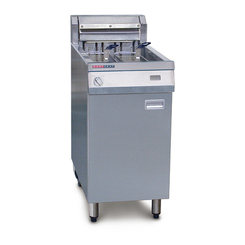
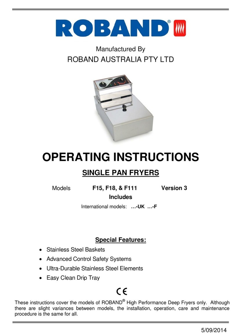
ROBAND Austheat AF812 User manual

Manufactured By
Instruction Manual
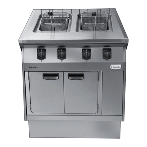
FREE STANDING FRYERS
AF812, AF812R,
AF813, AF813R
Version 7
AF822
Version 6

2
CONTENTS
Product Features 2
Specifications 2
Parts Included 2
Safety Instructions 3
Cleaning & Maintenance 3
Installation 4
Operation 5
Troubleshooting 8
Spare Parts 9
Circuit Diagram 10
Warranty 12
PRODUCT FEATURES
▪Swing Up Ultra-Durable Stainless Steel
Elements
▪Easy Clean Tank with Lockable 1” Drain
▪Adjustable Legs & Rear Castors
▪Digital LED Temperature Display
▪Fish Plate & Fish Plate Lifter
▪Stainless Steel Baskets
▪Cook/Idle Selector Switch
SPECIFICATIONS
Model
Power (kW)
(400VAC
3 PHASE +
NEUTRAL)
Size (mm)
Weight
(kg)
Oil Volume
(L)
Recommended
Batch Load per
Basket (kg)
W
D
H
AF812
14.5
450
800
1080
75
29
1.25
AF812R
16.6
29
AF813
16.6
600
87
39
AF813R
21.5
39
AF822
14
450
113
15
*Specifications subject to change
PARTS INCLUDED
1. AF Fryer
2. Fryer baskets
3. Tank lid/lids
4. Fish plate
5. Strainer
6. Fish plate lifter
7. Drain pipe extension
8. Instruction Manual
Any damage to the machine as a result of
freight must be reported to the Freight
Company and to the agent responsible for the
despatch of machine within 24 hours of receipt.
No claims will be accepted after this period.

3
SAFETY INSTRUCTIONS
Read all Instructions and safety warnings prior to
use. Keep user manual for future reference.
Service and repair should only be performed by
qualified technicians who have read and
understand this manual.
Personnel must be trained prior to operating
this appliance.
This product is suitable for commercial use only.
This machine should not be operated by
persons (including children) with reduced
physical, sensory or mental capabilities, or lack
of experience or knowledge, unless they have
been given supervision or instruction concerning
the safe use of the appliance by a person
responsible for their safety.
Keep out of reach from children.
Avoid contact with the exterior of this machine
as surfaces can get hot.
Do not position appliances where hot surfaces
may be accidently touched.
The machine should be disconnected from all
power and allowed to cool before cleaning or
servicing.
Regularly inspect the supply cord/plug and
discontinue use immediately if damage is found.
Return to manufacturer or authorised repairer
for repair prior to use.
This machine contains no user-serviceable parts.
Roband Australia®, one of our agents, or a
similarly qualified person(s) should carry out
repairs.
Keep cord away from heated surfaces.
Do not remove any cover panels from the
machine.
Roband will accept no liability if:
▪Non-authorised personnel have tampered
with the machine
▪The instructions in this manual have not
been followed
▪Non-original spare parts are used
▪There is any damage to the unit
CLEANING & MAINTENANCE
CAUTION: Disconnect power and allow
machine to cool before cleaning.
CAUTION: Steel cutting processes used in the
construction of this appliance can result in sharp
edges. Avoid contact with sharp edges during
cleaning and maintenance.
Do not clean with the use of a water jet or
immerse in water.
Do not use caustic or abrasive cleaning products
as they will damage the appliance.
With the exceptions of the cooking baskets, lids,
fish plates and strainers, never immerse in water
for cleaning or any other purpose.
The fryer should be cleaned out daily, or more
often if necessary.
Wipe all surfaces of the appliance with warm
soapy water using a damp non-abrasive cloth.
Regular cleaning will prevent a build-up of oils
and keep the appliance looking new.
Filter the cooking oil daily if the fryer is
constantly in use.
TO EXTRACT ELEMENTS FROM THE TANK
•turn off machine and wait until cool
•remove fish plate using fish plate lifter
(located inside the door)
•Access
lifting
handle

4
INSTALLATION
These fryers are designed as floor mounted
units. The unit can be moved by lifting
underneath the display panel and pulling it
along on the castors. Be careful when lifting.
This is a heavy machine and can become
unbalanced if lifted excessively.
Remove all packaging materials, tape, and any
protective plastic from the appliance. Remove
any glue residue from the protective plastic or
tape using citrus cleaner.
Place the free standing fryer on a firm, level floor
in the required position. The legs can be
adjusted for slightly uneven floors.
National Standards exist outlining the
positioning, spacing and ventilation
requirements when installing new appliances.
These Standards should be consulted and new
equipment should be installed accordingly.
Regardless of the situation, Roband Australia
recommends a well-ventilated air gap of not less
than 100mm be maintained. If the machine is
near particularly heat-sensitive materials
common sense should be employed in
determining sufficient distancing.
Consideration should be given to securing the
unit or limiting mobility if the unit is hard-wired.
Appropriate standards should be consulted
when any installation is undertaken to ensure
compliance with all requirements.
ELECTRICAL CONNECTION
See specification table for fryer electrical data.
Before connecting the fryer to the power supply,
ensure that all the controls are in the “OFF”
position.
A licensed electrician must install this fryer to
comply with national installation codes and
regulations. The fryers are supplied ready for
connection to a three phase, plus neutral and
earth mains supply. Means for disconnection
from supply must be incorporated in the fixed
wiring in accordance with the wiring rules.
WARNING - THIS UNIT MUST BE EARTHED.
Each fryer must be connected to an adequately
protected power supply and an isolation switch
mounted adjacent to, but not behind the fryer.
This switch must be clearly marked and readily
accessible in case of fire.
WARNING: Do not power on the unit without oil
in the tank.
•Lift elements until they latch open
•To lower elements, use release catch
CABLE ACCESS OPTIONS
USE SUITABLE CABLE GLAND

5
OIL TYPES
EXTRA VIRGIN OLIVE OIL
The flash point of Extra Virgin Olive Oil is
considerably lower than the more refined Olive
oils and should not be used for high
temperature frying.
TALLOW-BASED (BEEF) FATS
The most commonly used fat due to its cheaper
cost and relatively longer fry life. This medium is
not recommended due to its association with
increased risk of heart disease.
LIQUID VEGETABLE OILS
While most vegetable oils are recommended for
cooking, many of them are not suitable for
deep-frying. Higher temperatures break down
the oil faster and by-products often have an
unpleasant flavour and may also have an
association with increased risk of heart disease.
HARDENED/CREAMED VEGETABLE OILS
These products may have a longer fry life than
their liquid oil equivalents, but the components
added during the hardening process increase
the risk of heart disease.
The Heart Foundation recommends frying oils
that have a nutrient profile taking all these
factors into account. These include:
1. Oils from specially bred seeds e.g. Sunola,
Liquid Gold
2. Industry blends of fats and oils
OPERATION
OIL LEVEL
A high & low oil level limit has been etched into
the side of the tank. The upper and lower lines
of the etched marking indicate the upper and
lower oil level limits.
The danger of fire exists if the oil level is below
the minimum indicated level.
The danger of surge boiling exists if the oil is
above the maximum indicated level.
The danger of surge boiling also exists if over-
wet or too large a load is used
Refer to the specifications page for the volume
of oil required for your particular model.
FILLING WITH LIQUID OIL
Fill the tank with the required volume of oil
using the following procedure.
•Ensure all controls are OFF, the drain valve
is closed and the elements are cold.
•Place the strainer in position, lower the
elements and place the fish plate in
position.
•Fill the tank with the required volume of oil.
•The fryer is now ready for cooking.
THE MELT CYCLE - SOLID OIL
If solid oil or shortening is preferred this may be
melted after filling by using the melt switch and
the following procedure.
•Ensure all controls are OFF, the drain valve
is closed and the elements are cold.
•Place the strainer in position and lower the
elements. Do not place the fish plate into
the tank at this time.
•Fill the tank with solid oil/shortening to
sufficiently cover the elements.
•Switch the fryer ON at the main isolating
switch.
•With the thermostat selector switch set to
the PRIMARY position, set the primary
thermostat to 120°.
•Switch the melt switch to ON.
•Melt time approx. 40mins
•While melting, additional solid oil will need
to be added to achieve the correct oil level
•On completion, turn off melt switch and
install fish plate using the supplied fish plate
hook.
•The fryer is now ready for cooking.
MACHINE CONTROL
The controls are accessed via the front door,
located below the front display panel.

6
1. MAIN ISOLATING (ON/OFF) SWITCH
•Switches machine power on/off
2. PRIMARY (COOK) THERMOSTAT
•Controls the temperature of the oil
when COOK/IDLE SWITCH positioned
to COOK
3. SECONDARY (IDLE) THERMOSTAT
•Controls the temperature of the oil
when COOK/IDLE SWITCH positioned
to IDLE
•IDLE places the Fryer at a reduced
temperature set by the secondary
thermostat. This provides faster
recovery time to cook temperature
whilst saving power during low use
periods.
•The secondary thermostat can be used
as a redundant control thermostat if the
primary thermostat fails.
4. MELT SWITCH
•Activates the melt cycle for solid oil. See
section the Melt Cycle - Solid Oil
DISPLAY PANE LAYOUT
1. COOK/IDLE SELECTOR SWITCH
2. THERMOMETER - OIL TEMPERATURE
DISPLAY
DOUBLE TANK MACHINES
3. THERMOMETER - OIL TEMPERATURE
DISPLAY –RHS TANKS
4. COOK/IDLE SELECTOR SWITCH –RHS
TANK
Note that for double tank model (AF822), the
controls are duplicated for the left and right
tanks.
HEATING UP THE OIL
1. Fill the fryer tank with oil as described
above.
2. Rotate the main switch to the “ON”
position. The green pilot light will
illuminate, indicating that the power is on.
3. Rotate the COOK/IDLE selector
switch/witches to the COOK position.
4. Rotate the primary thermostat knob to
select the desired cooking temperature.
Roband Australia recommends a setting of
between 170° and 180°C.
When the machine is heating, the amber pilot
light adjacent to the thermostat knob will
illuminate. When the oil has reached the set
SINGLE TANK FRYERS
DOUBLE TANK FRYER
SINGLE TANK FRYERS
DOUBLE TANK FRYER

7
temperature the amber pilot light will be
extinguished.
The thermostat will then continue to cycle on
and off, maintaining the set temperature. The
amber pilot light will cycle on and off with the
thermostat.
The real time, fluctuating oil temperature is
measured and displayed on the digital display
on the control panel. Note: This is not a static
value equal to the set temperature of the
thermostat.
COOKING
Do not cook food until the oil has reached the
desired cooking temperature.
Do not overfill the baskets. . Refer to the
specifications page to determine the maximum
basket load.
Lower the filled baskets into the oil carefully.
Shaking the baskets occasionally during cooking
will help prevent the food from sticking
together.
Cooking time will vary with the type of food
product being cooked and experience should
guide you.
To obtain the optimum results from your fryer
we recommend the following guidelines.
•Keep salt away from the cooking oil. Salt
degrades the oil.
•Check your oil to food ratio, 6:1 oil to food
is recommended.
•Top up the cooking oil regularly.
THERMAL CUT-OUT
These fryers have TWO safety thermostats (or in
the case of the AF822, FOUR). They function to
remove power from the cooking elements when
any of the below scenarios are met:
•The oil reaches a dangerous temperature.
•The oil volume drops below the low level
marker.
•Cooking elements are not sufficiently
submerged in oil/ exposed to air.
If any of these conditions occur, one or both
thermal cut-outs will trip, cutting power to the
elements.
The symptoms of a trip of the rear thermal cut-
out are:
•Power pilot light (green) still illuminated
(assuming main switch is on)
•Thermostat pilot lights off (regardless of
thermostat knob position and oil
temperature)
•Melt switch pilot off (either switch position)
•Oil temperature on digital display dropping
to ambient
The symptoms of a trip of the front thermal cut-
out are:
•All pilot lights are still functional
•Oil temperature on digital display dropping
to ambient
•Thermostats never cycle off (assuming the
thermostat setting is above the temperature
on the digital display)
The thermal cut-out reset button locations are
given below:

8
When tripped, a red button on the device will
protrude out from the panel where it is located.
If the thermal cut-out has tripped, it indicates
that there is an underlying problem that has
caused the oil to reach a dangerous
temperature.
Note: It is important to understand that old,
dirty or low level oil can contribute to nuisance
tripping of the thermal cut-outs. Always ensure
that your oil is maintained and replaced when
necessary.
If a thermostat has failed for the first time:
1. Switch the fryer OFF and allow it to cool to
approximately 100°C.
2. Visually determine which of the two thermal
cut-outs has tripped.
3. Reset the thermal cut-out by pressing the
red reset button. The control is reset when
the button remains depressed. An audible
click will also be heard.
4. Re-set the control thermostat to the normal
operating temperature and observe the unit
closely. If the unit trips the thermal cut-out
again, continue to step 5. If no cut-out
occurs within an hour, continue to use the
machine and monitor the temperature of the
oil.
5. If the thermal cut-out switch trips again, set
the thermostat selector switch to the
SECONDARY/IDLE position. This procedure
assumes you were using the primary
thermostat. If you were using the secondary
thermostat when the fault occurred, then
select the PRIMARY/COOK position in this
procedure.
6. Cooking can now resume.
If the fryer continues to perform without any
further tripping of the thermal cut-out, it is likely
that the thermostat in use at the time is faulty.
This should be attended to by qualified
electrical personnel.
If the thermal cut-out trips again after following
the above procedure, it indicates that there is a
serious electrical problem that needs to be
addressed immediately. In such cases follow the
procedure below.
1. Turn OFF the fryer immediately. There may
be a danger of fire.
2. DO NOT reset the thermal cut-out.
3. Seek advice from qualified electrical
personnel. They will be able to check the
fryer for faults and make any necessary
repairs.
Resume operation of the fryer only after it has
been cleared for use by the electrical personnel
charged with the repair.
TROUBLESHOOTING
If the fryer does not function check the following
points before calling for service.
▪The power is switched “on”, both on the
unit and at any other point that supplies
power to the machine (eg an isolating
switch on the wall).
▪The mains power is not faulty.
▪The temperature has been set correctly and
the thermal cut-out has not tripped. Refer
to the “Thermal Cut-Out” section previous
for more information on this control.
▪The thermostat knobs are not loose or
broken, rendering the thermostats
inoperable.
▪The circuit breakers located inside the door
behind the drains are all in the “on”
position”.
→.

9
SPARE PARTS
Common
EC0184
Pilot - 6.3mm Amber, 2-piece T120
EC0206
Pilot - 6.3mm Green, 2-piece T120
EC0245
Rail Mounted Terminal Block Red 65A
EC0246
Rail Mounted Terminal Block Blue 65A
EC0247
Rail Mounted Terminal Block- Earth
EC0249
Rail Mounted Terminal Block - Link (2 pole)
EC0257
Circuit Breaker - 40A, miniature (3KA)
EC0258
Circuit Breaker - 6A, miniature (3KA)
EC0367
Long Roller Microswitch
ES0206
Switch - 2 Pole Changeover & Alu Knob
ES0212
Microswitch, Arm and Bracket
ES0231
Digital Thermometer - Modified
HC0141
Element - 125W 230V
MC0067
Gland - Universal Stuffing
MC0074
Lifter - Donut / Fish Plate
MC0093
Clamp - cable
MC0609
Adjustable Leg - 150mm S/S Leg, Insert &
Mounting Plate
MC0610
Castor
MC0611
Basket - Large Fryer
MC0691
Valve - Drain, 1" ball with lockable lever
MC0846
Knob & Spring-Roband Satin Finish-6mm 0°
MS0355
Thermometer Probe (K Type
Thermocouple) , Washer & Nut
MS0371
Hinge - Door
MS0386
Drain Pipe & Ball Valve Assembly - 1" ball
lockable
SS1888
Circuit Breaker Cover
TC0001
Energy Regulator (includes nut)
TC0026
Thermostat - Limit, 240°C -13K
TS0005
Thermostat - 205°C & Plain Knob
AF812
EC0218
Switch - Rotary, Mains Isolator - 4 pole 25A
per pole
EC0256
Contactor - 30A 240V/50Hz
HC0149
Element - 4800W 230V
PC0317
Washer Klingerite 27mm x 17mmID
SS1813
Lid Assembly
SS1877
Door Assembly
SS1955
Strainer
SS1966
Fish Plate
AF812R
EC0232
Switch - Rotary, Mains Isolator - 4 pole 32A
per pole
EC0259
Contactor - 40A 240V/50Hz
HC0151
Element - 5500W 230V (for 18kW machines)
SS1813
Lid Assembly
SS1877
Door Assembly
SS1955
Strainer
SS1966
Fish Plate
AF813
EC0232
Switch - Rotary, Mains Isolator - 4 pole 32A
per pole
EC0259
Contactor - 40A 240V/50Hz
HC0151
Element - 5500W 230V (for 18kW
machines)
SS1832
Lid Assembly
AF813R
EC0259
Contactor - 40A 240V/50Hz
EC0272
Switch - Rotary, Mains Isolator - 4 pole 40A
per pole
HC0149
Element - 4800W 230V (For 15kW
Machines & 813R)
HC0153
Element - 2300W 230V (Fryer)
SS1832
Lid Assembly
AF822
EC0218
Switch - Rotary, Mains Isolator - 4 pole 25A
per pole
EC0256
Contactor - 30A 240V/50Hz
EC0260
Switch - Rocker Changeover 2-pole
HC0153
Element - 2300W 230V (Fryer)
SS1870
Fish Plate
SS1871
Strainer
SS1877
Door Assembly
SS1889
Lid Assembly

CIRCUIT DIAGRAM
MODELS: AF812, AF812R, AF813, AF813R

11
MODELS: AF822

WARRANTY
The warranty conditions set out below are in addition to any warranties implied or governed by law.
Roband Australia warrants that this appliance shall be delivered free from defects in material and workmanship.
The warranty for this product is offered to the original purchaser, to be free of fault in both workmanship and
materials for a period of 12 months from date of purchase. Roband’s obligations pursuant to this warranty are
limited to the repair or replacement of the defective goods or materials, at its discretion and subject to the
terms contained within this Warranty statement.
The following conditions apply:
The product must be installed, maintained and used under normal operating conditions within the scope of the
operating instructions.
All warranty claims must be submitted to Roband or an authorised Roband dealer, and Roband authorisation
must be granted prior to repairs being carried out. Proof of purchase is required for any repair authorisation.
Warranty is back to base, meaning delivery to and collection of your product to Roband or an authorized
service agent is the responsibility of the purchaser.
Where a product cannot be returned back to base, on-site warranty can be arranged by prior agreement.
The following exclusions apply:
Claims or faults arising from misuse, neglect, transport damage or other mechanical damage, including but not
limited to; door’s, hinges & interlock switches etc., other than those arising from manufacture or material
defects. Where relevant, glass, Teflon® and lamps are not included in this warranty and RCD tripping due to
moisture absorption by Tubular Heating Elements is not a warranty fault.
Roband or any subsidiary company or Agent shall not be liable for loss of profit or damage to other equipment
and property except where it is in breach of the guarantees provided in accordance with applicable legislation.
Roband reserves the right to reject a warranty claim if it is not satisfied with the circumstances under which the
fault occurred or where a product has been altered from its original specification.
For on-site repairs outside of capital city metropolitan areas, travel costs, service callout fee and related labour
costs etc. are the responsibility of the claimant.
Any costs incurred for false claims or faults due to incorrect usage etc. are the responsibility of the claimant.
Any attempt to repair the product by non-Roband approved service personnel or the use of non-genuine parts
will void the warranty agreement
Our goods come with guarantees that cannot be excluded under the Australian Consumer Law. You are
entitled to a replacement or refund for a major failure and compensation for any other reasonably foreseeable
loss or damage. You are also entitled to have the goods repaired or replaced if the goods fail to be of
acceptable quality and the failure does not amount to a major failure.
Extended Warranty;
You are entitled to a five (5) year extended warranty on the fryer tank, a two (2) year extended warranty on
parts, in conjunction with one (1) year labour coverage.
The extended warranty application form on the Roband website must be completed and submitted to Roband
within 30 days of purchase.
For the name of your nearest Australian authorised service agent, please contact:
Roband Australia Pty Ltd
1 Inman Road,
Cromer, NSW, 2099, Australia
Warranty: 1800 268 848
Tel: +61 2 9971 1788
Email: sales@roband.com.au
Web: www.roband.com.au
For your nearest International distributor,
please visit:
https://www.roband.com.au/worldwide/
Other manuals for Austheat AF812
1
This manual suits for next models
4
Table of contents
Other ROBAND Fryer manuals
