Robert Juliat DALIS 860 CYCLIODE User manual

DALIS - 860
Version V2 –01/04/16
DN41077600
Robert Juliat S.A.S. 32, rue de Beaumont, F60530 Fresnoy-en-Thelle - phone : +33 (0)3 44 26 51 89 - fax : +33 (0)3 44 26 51 89 - inf[email protected]
www.robertjuliat.com
Dalis - 860
Cycliode
Cyclight
Cycliode 300W LED 8 couleurs
8 colours LED 300W Cyclight
Manuel / Manual

Robert Juliat reserve the right to change
or alter any of the items detailed on this page,
to increase or improve manufacturing techniques without prior notice.
Table of contents
1User’s instructions ............................................................................................................................ 1
2Presentation ..................................................................................................................................... 2
2.1 Functions................................................................................................................................. 2
2.2 Identification plate.................................................................................................................... 2
2.3 Accessories included............................................................................................................... 3
2.4 Optional accessories ............................................................................................................... 3
3Set-up............................................................................................................................................... 4
3.1 Mechanics................................................................................................................................ 4
3.2 Electrical.................................................................................................................................. 9
3.3 DATA..................................................................................................................................... 10
4Operation........................................................................................................................................ 12
4.1 Light intensity......................................................................................................................... 12
4.2 Colours .................................................................................................................................. 13
4.3 Colour presets ....................................................................................................................... 15
4.4 CCT ....................................................................................................................................... 17
4.5 Strobe.................................................................................................................................... 17
4.6 Group..................................................................................................................................... 18
4.7 Response time....................................................................................................................... 20
5Control and parameters ................................................................................................................. 21
5.1 Local display and Controls .................................................................................................... 21
5.2 DMX512-A remote control..................................................................................................... 23
5.3 RDM remote control .............................................................................................................. 27
5.4 Art-Net remote control ........................................................................................................... 28
5.5 sACN remote control ............................................................................................................. 29
6Service ........................................................................................................................................... 30
6.1 Preventive maintenance........................................................................................................ 30
6.2 Analysis ................................................................................................................................. 30
6.3 Electronic thermal management system ............................................................................... 30
6.4 Firmware update.................................................................................................................... 30
6.5 Factory defaults..................................................................................................................... 30

EN
EN -1-
1 User’s instructions
GENERAL INSTRUCTIONS
1. Not for residential use.
2. These fixtures must only be serviced by a qualified technician.
3. In addition to the instructions indicated on this page, relevant health and safety requirements of the appropriate EU
Directives must be adhered to at all times.
4. This fixture is in compliance with section 17 - Lighting appliance for theatre stages, television, cinema and photograph
studios. Standards NF EN 60598-1 and NF EN 60598-2-17.
5. This fixture is rated as IP20, and is for indoor use only.
FIXTURE
6. Ensure fixture is correctly mounted on an appropriate support.
7. Protection screens must be replaced in the event of any damage, such as cracks or deep scratches, since these might
reduce performance.
8. When hung or flown the fixture must be secured by an additional hanging accessory (such as a safety cable or bond) of
suitable length –only use Robert Juliat safety cables ref. QR-CS1
9. Safety bonds or cables must be securely attached to the QuickRig system of the fixture and be as short as possible, or
rolled up as necessary, to minimise travel distance should the fixture be dislodged. .
10. WARNING: LED source become hot during use. Allow fixture to cool before servicing.
11. Do not tamper with design of fixture nor any of its safety features.
12. Tighten electrical mains cable connections regularly and replace with one of identical specification if damaged.
13. Use only with correct power supply.
14. Do not orientate the fixture towards a source of light (sun, fixture), in particular for LED versions.
VENTILATION
15. Keep well away from flammable material.
16. Not for outdoor use. Do not cover. Do not permit fixture to get wet.
17. To avoid overheating, do not obstruct air vents –do not cover the unit.
PLEASE NOTE
These products have been built to conform to European standards relating to professional lighting equipment. Any modification
made to our products will void the manufacturers' warranty.

EN
EN -2-
2 Presentation
2.1 Functions
Functions :
1. Feet
2. QuickRig rail
3. ID plate
4. Power IN
5. DMX IN
6. Network
7. NFC sensor
8. Display and keypad
9. DMX OUT
10. Power OUT
2.2 Identification plate
Description :
1. Model :
2. Version :
3. Serial number
4. Serial number in barcode format

EN
EN -3-
2.3 Accessories included
Reference
Description
1
COU0003305
Neutrik PowerCon© True1 connector (ref. NAC3FX-W)
2
DN41086000
Quick Start manual
2.4 Optional accessories
Reference
Description
1
CAL03
3 meter power cable ( 3G1,5 HO7RNF) with Neutrik PowerCon© True1 and
CEE 7/7 (2P+T NF/SCHUKO) connectors
2
CAL04
1,50m power cable UL/CSA with Neutrik PowerCon© connector
3
CAL05
Combined Neutrik PowerCon© True1 / DMX (5 pins) patch cable - length: 1m
4
QR-CS1
QuickRig safety cable Ø3mm L=600mm - SWL: 20 Kg
5
QR-Pin
16mm QuickRig pin
6
885
Doughty "Supaclamp" (black) with 16mm spigot hole for Ø50mm pipes max. -
SWL: 20Kg - Weight: ,45 Kg
7
QR-Pin2
M10 QuickRig socket (without screw)
8
872
Doughty "Twenty clamp" with M10 screw/nut for Ø48 to 51mm pipes - SWL:
20Kg - TÜV approved

EN
EN -4-
3 Set-up
3.1 Mechanics
3.1.1 Operating positions
3.1.2 Minimum distance between a flammable material and the lighting unit
3.1.3 Instructions for use
Minimum :
5°C
41°F
Maximum :
40°C
104°F
IP20 –Indoor use only
Do not cover the front side
Covering cooling zones 1 & 2 with tape or gel filters result in overheating
0,2 m
0.7 ft

EN
EN -5-
3.1.4 Recommended distances
Dalis has been designed to be installed in a complete continuous row.
Example: for a 10m wide cyclorama, 10 pieces of 1m DALIS are required.
However, Dalis can be distanced with a gap of 30/50 cm. This arrangement does not affect the
evenness and output, it will only minimise the colour fading possibilities.
Depending on the height of the cyclorama and the effect required (evenness of the lighting on the
cyclorama), 1 row (bottom or top) or 2 rows (bottom and top) can be installed.
Below are recommended distances for the best evenness of light on cyclorama. Depending on the
lighting designer expectations, the units can be installed closer to the cyclorama.
Influence of the cyclorama:
Transmission (rear projection) or reflection (front projection) can be different depending
on cyclorama material. Contact your cyclorama supplier for more information

EN
EN -6-
3.1.5 Floor installation
1 & 2 = Tilt Up / 3 & 4 = Tilt Down
3.1.6 Top / side installation
Ensure fixture is correctly mounted on an appropriate support.
The fixture must be installed with 2 clamps.
Net weight : 11Kgs
1.
2.

EN
EN -7-
3.
4.
5.
X 2

EN
EN -8-
3.1.7 Safety cable
When hung or flown, the fixture must be secured by an additional hanging accessory (such as
safety bond or cable) of suitable length.
Safety cables or bonds must be securely attached to the back of the fixture and be as short as
possible, or rolled up as necessary, to minimise travel distance should the fixture be dislodged.
1
3.1.8 Angular sensor
selection in STATUS/ANGULAR ADJUSTMENT menu
A
B
C
Horizontal position
Vertical position
A
B
A
C

EN
EN -9-
3.2 Electrical
3.2.1 Power
Voltage
Frequency
Input power
Connectors
90 265 V
50-60 Hz
1.5A / 300 W @ 230V
3.4 A / 300 W @ 115V
Max.4 A
Neutrik powerCON TRUE1
ref. NAC3FPX (max. 20A)
see appendix 1 for
assembly instructions
Class 1 product. This luminaire must be grounded.
Must be connected directly to AC power. Do not connect to dimmer power.
Automatic power detection.
Daisy chain: maximum of 12 units (230V) / 6 units (110V)
Daisy chain (with optional patch cable):
3.2.2 Power cable
Power cable
Power cable
Connector
Mains plug
Cable
type
Cable
length
Wiring
1
Standard version
Neutrik
PowerCon®
NAC3FX
CEE7/7
3G1.5
H07RNF
3 m
9.8 ft
Live: Brown
Neutral: Blue
Ground:
Yellow/Green
2
North American
version
-
14AWG
SJ TYPE
(UL/CSA)
1.5 m
4.9 ft
Live: Black
Neutral: White
Ground: Green
In
Out
Maximum:
12 units (230V)
6 units (120V)

EN
EN -10-
3.3 DATA
3.3.1 DMX 512-A / RDM
Protocol
Input connector
Output connector
USITT DMX 512-A
RDM
XLR 5-pin
XLR 5-pin
3.3.2 Art-Net / sACN
Protocol
Input connector
Output connector
Art-Net
sACN
RJ45
-
DATA connectors
PIN #
DMX
Description
1
Shielding
Foil & Braided Shield
2
DMX (-)
1st conductor of 1st twisted pair
3
DMX (+)
2nd conductor of 1st twisted pair
4
Not used
1st conductor of 2nd twisted pair
5
Not used
2nd conductor of 2nd twisted pair
Daisy chain
DMX Console
Art-Net
sACN
Network
switch
Maximum:
32 units
DMX Console

EN
EN -11-
3.3.3 Ethernet/DMX node
Protocol
Input connector
Output connector
Art-Net
sACN
RJ45
DMX
3.3.4 NFC
soon available
Maximum:
32 units
DMX Console
Art-Net
sACN
DMX
EN
EN -12-
4 Operation
4.1 Light intensity
4.1.1 Range
4.1.2 Control
Remotely with
DMX512-A / Artnet / sACN protocols
Mode 1 –2 –3 –4 –5 –6
Locally via STAND ALONE mode
4.1.3 Parameters
4.1.3.1 Dimming resolution
Resolution
DMX mode :
8 bits –255 steps
3 –5 –STAND ALONE
16 bits –65 535 steps
1 –2 –4 –6
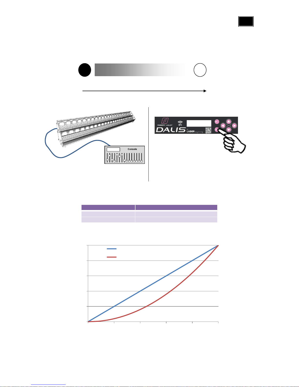
4.1.3.2 Dimming curve
selection in SETUP/DIMMER CURVE menu: Linear or Square
0
20
40
60
80
100
020 40 60 80 100
Light output (%)
Control (%)
Linear
Square
Console
0 %
100 %

EN
EN -13-
0 %
100 %
0 %
100 %
0 %
100 %
0 %
100 %
0 %
100 %
0 %
100 %
0 %
100 %
0 %
100 %
4.2 Colours
4.2.1 Range
Red
Green
Blue
Royal blue
Cyan
Amber
Cool white 6500K
Warm white 2200K

EN
EN -14-
4.2.2 Control
Remotely with
DMX512-A / Art-Net / sACN protocols
Mode 1 –2 –3 –6
4.2.3 Parameters
4.2.3.1 Resolution
Resolution
DMX mode :
8 bits –255 steps
3
16 bits –65 535 steps
1 –2 –6
4.2.3.2 Intensity curve
4.2.3.3 Cyan correction
selection in SETUP/CYAN CORRECTION menu: OFF or ON
Correction
Colour compatibility
OFF
Dalis V2
≠
Cyan colour is slightly different
Dalis V1
ON
Dalis V2
=
Cyan colour of V2 is equivalent to V1
by addition of colour combination
Dalis V1
0
20
40
60
80
100
020 40 60 80 100
Light output (%)
Control (%)
Linear
Console

EN
EN -15-
4.3 Colour presets
4.3.1 Range
Each preset has been calibrated by comparison with 1000W tungsten cyclight.
#
Gel reference*
1
L203: 1/4 CTB (E-color 203)
2
L202: 1/2 CTB (E-color 202)
3
L201: Full CTB (E-color 201)
4
L200: Double CTB (E-color 200)
5
L204: Full CTO (E-color 204)
6
L205: Half CTO (E-color 205)
7
E-Color 242: Fluorescent 4300K (L242 Fluorescent 4300K)
8
E-Color 241: Fluorescent 5700K (L241 Fluorescent 5700K)
9
E-Color 174: Dark steel blue (L161 Slate blue)
10
E-Color 161: Slate blue (L161 Slate blue)
11
E-Color 165: Daylight blue (L165 Daylight blue)
12
E-Color 353: Lighter blue (L353 Lighter blue)
13
Supergel 68: Parry sky blue (L68 Sky blue)
14
Supergel 79: Bright blue (L79 Just blue)
15
Supergel 82: Surprise blue (L723 Surprise blue)
16
E-Color 119: Dark blue (L119 Dark blue)
17
E-Color 363: Special medium blue (L363 Special medium blue)
18
E-Color 122: Fern green (L122 Fern green)
19
E-Color 124: Dark green (L124 Dark green)
20
E-Color 138: Pale green (L138 Pale green)
21
E-Color 134: Golden amber (L134 Golden amber)
22
E-Color 147: Apricot (L147 Apricot)
23
E-Color 101: Yellow (L101 yellow)
24
E-Color 105: Orange (L105 orange)
25
E-Color 344: Violet (L328 Follies pink)
26
E-Color 180: Dark lavender (L706 King fals lavender)
27
E-Color 106: Primary red (L182 Light red)
28
White : 6500 Kelvin
29
White : 6000 Kelvin
30
White : 5600 Kelvin
31
White : 4200 Kelvin
32
White : 4000 Kelvin
33
White : 3500 Kelvin
34
White : 3200 Kelvin
35
White : 3000 Kelvin
36
White : 2700 Kelvin
37
White : 2200 Kelvin
*L = Lee Filter
E-color = Rosco E-color
Supergel = Rosco Supergel

EN
EN -16-
4.3.2 Control
Remotely with
DMX512-A / Art-Net / sACN protocols
Mode 4 –5
Locally via STAND ALONE mode
4.3.3 Parameters
4.3.3.1 Resolution
Resolution
DMX mode :
8 bits –255 steps
5
16 bits –65 535 steps
4 –STAND ALONE
4.3.3.2 Cyan correction
selection in SETUP/CYAN CORRECTION menu: OFF or ON
Correction
Colour compatibility
OFF
Dalis V2
≠
Cyan colour is slightly different
Dalis V1
ON
Dalis V2
=
Cyan colour of V2 is equivalent to V1
by addition of colour combination
Dalis V1
Console

EN
EN -17-
4.4 CCT
4.4.1 Range
4.4.2 Control
Remotely with
DMX512-A / Art-Net / sACN protocols
Mode 4 –5
4.5 Strobe
4.5.1 Range
Strobe duration
Strobe speed
4.5.2 Control
Remotely with
DMX512-A / Art-Net / sACN protocols
Mode 1 –2 –3 –4 –5
Console
0=5,8Hz
255=11,5Hz
Console
0=OFF
1=1ms
255=85ms
OFF
0 % = 2200K
100 % = 6500K

EN
EN -18-
4.6 Group
4.6.1 Range
Group 1
Group 2
Group 3
Group 4
4.6.2 Control
Remotely with
DMX512-A / Art-Net / sACN protocols
Mode 1 –6
Console
Other manuals for DALIS 860 CYCLIODE
1
Table of contents
Other Robert Juliat Projector manuals


