Warnings
6
III
Aggressive substances in the air
Halogenated hydrocarbons containing chlorine
and uorine compounds cause corrosion. The air
of the installation site must be free from aggressive
substances.
Acid ue gas condensate
Discharge the acid condensate of combustion ue
gasincompliancewithcurrentexhaustregulations.
Switching the appliance o
Disconnecting the power supply while the appli-
ance is running may cause permanent damage to
internal components.
Except in the case of danger, do not disconnect
the power supply to switch o the appliance, but
always and exclusively act through the provided
control device (DDC, CCI or external request).
In the event of failure
Operations on internal components and repairs
may exclusively be carried out by a TAC, using only
original spare parts.
In the event of failure of the appliance and/or
breakage of any component, do not attempt to
repair and/or restore and immediately contact the
TAC.
Routine maintenance
Proper maintenance assures the eciency and
good operation of the appliance over time.
Maintenance must be performed according to the
manufacturer's instructions (see Chapter 7
p. 32
)
and in compliance with current regulations.
Appliance maintenance and repairs may only be
entrusted to rms legally authorised to work on
gas appliances and systems.
Enter into a maintenance contract with an author-
ised specialised rm for routine maintenance and
for servicing in case of need.
Use only original parts.
Decommissioning and disposal
If the appliance is to be disposed of, contact the
manufacturer for its disposal.
Keep the Manual
This Installation, use and maintenance manual
must always accompany the appliance and must
be handed to the new owner or installer in the
event of sale or removal.
III.2 COMPLIANCE
III.2.1 EU directives and standards
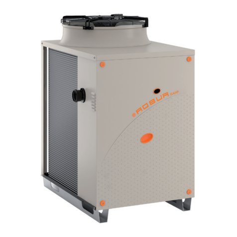
The absorption heat pumps of the GAHP series are certi-
ed as conforming to standard EN 12309 and comply with
the essential requirements of the following Directives:
▶
2016/426/EU "Gas Appliances Regulation" as amend-
ed and added.
▶
2014/30/EC "Electromagnetic Compatibility Directive"
as amended and added.
▶
2014/35/EC "Low Voltage Directive" as amended and
added.
▶
2014/68/EU "Pressure Equipment Directive" as amend-
ed and added.
▶
811/2013/EU "Energy-Related Products regulation" as
amended and added.
▶
813/2013/EU "Ecodesign requirements regulation" as
amended and added.
Furthermore, they comply with the requirements of the
following standards:
▶
EN 378 Refrigerating systems and heat pumps.
III.2.2 Other applicable provisions and standards
The design, installation, operation and maintenance of
the systems shall be carried out in compliance with cur-
rent applicable regulations, depending on the Country
and location, and in accordance with the manufacturer's
instructions. In particular, regulations regarding the fol-
lowing shall be complied with:
▶
Gas systems and equipment.
▶
Electrical systems and equipment.
▶
Heating and cooling systems, and heat pumps.
▶
Environmental protection and combustion products
exhaust.
▶
Fire safety and prevention.
▶
Any other applicable law, standard and regulation.
III.3 EXCLUSIONS OF LIABILITY AND
WARRANTY
Any contractual or extra-contractual liability of the
manufacturer for any damage caused by incorrect
installation and/or improper use and/or failure to
comply with regulations and with the manufactur-
er's directions/instructions shall be disclaimed.
In particular, the warranty on the appliance may be
rendered void by the following conditions:
Incorrect installation.
Misuse.
Failure to comply with the manufacturer's indica-
tions on installation, use and maintenance.
Alteration or modication of the product or any
part thereof.
Extreme operational conditions or however out-
side of the operational ranges set forth by the man-
ufacturer.


