AWG SWIMSMART SS110 User manual

OWNER’S MANUAL
INSTALLATION, OPERATION
MAINTENANCE & SERVICE
SWIMSMART HEAT PUMPS
BY AWG
888-475-7443 (HEAT)
Models:
SS110
SS55
SS93

2
WARNING:
• Qualified personnel should perform installation, maintenance and service.
• Make sure all field wiring conforms to the heater specifications and all national and local codes.
• Disconnect all power sources before performing any maintenance or service to the heater.
INSPECTION
Immediately upon receipt, inspect cartons and their contents for damage due to transit.
Damage, if found, should be noted on delivery papers and a claim filed with the carrier. Also,
check unit data plate to make sure you have the proper model, before installing.
GENERAL INFORMATION
The information in this manual was prepared to assist in the proper installation, operation,
maintenance and service of your new heat pump pool heater. Please read the entire manual and
follow all instructions. Improper installation and use can result in damage to the heater,
unsatisfactory operation, and may void the warranty. Retain this manual for quick reference.
CAUTION:
When selecting a location consider the following:
• Heater must be located outdoors.
• Minimum of 24” of clearance on access / service side of heater.
• Minimum of 18” of clearance on all three air intake sides of heater.
• Minimum of 48” of clearance for air discharge (top of unit).
• The heater should sit on a solid level surface sufficiently above grade to prevent water from
entering it from underneath, and allowing condensate to drain from base.
• The length of water piping and electric should be kept to a minimum to avoid capacity
loss and decreased efficiency.
WATER FLOW & CONNECTIONS
Water connections are made at the front or rear of the heater. Water in and out is labeled at the connections.
The minimum flow rate is 15 g.p.m. and the maximum flow rate is 50 g.p.m. for SS110
NOTE: Unions can be used for quick drainage of your heater and winterizing.
• Heater must be piped downstream from filter in the pool return line.
• When all the plumbing connections are complete, and ample drying time is allowed, run
the filter pump and check the entire system for water leaks.
• Make sure filter is clean and there are no obstructions in the filtering system.
• Proper water flow is essential to the performance of your heat pump.
LOCATE THE HEAT PUMP AT LEAST 5 FEET FROM POOL WALL ACCORDING TO CODES
SAFETY CONSIDERATIONS
INSTALLATION
The minimum flow rate is 20 g.p.m. and the maximum flow rate is 70 g.p.m. for SS55 and SS93

WATERFLOW CONNECTIONS
A. TYPICAL INSTALLATION
SWIMSMART
HEAT PUMP
PUMP
FROM
MAIN DRAIN /
SKIMMER
RETURN
CHLORINATOR
OR
OZONATOR
WATER IN WATER OUT
FILTER
B. INSTALLATION WITH A
POOL AND SPA
SWIMSMART
HEAT PUMP
PUMP
FROM
MAIN DRAIN /
SKIMMER
RETURN
BALL VALVE
FOR FLOW RATES
GREATER THAN 50 G.P.M.
WATER IN WATER OUT
FILTER
3 WAY VALVE
3 WAY
VALVE
SPA
N.O. EXTERNAL
PRESSURE SWITCH
TO P/S ON
HEAT PUMP
CONTROL
BALL VALVE
FOR FLOW RATES
GREATER THAN 50 G.P.M.
CHLORINATOR
OR
OZONATOR
3

4
Disconnect all power sources before performing any work on unit.
Field connections must comply with national and local codes.
Plug only into a GFCI protected outlet
Do NOT use extension cord to extend length of power cord
GFCI outlet used for heat pump requires a 20 Amp breaker
HEATER MUST BE PERMANENTLY GROUNDED AND BONDED.
BONDING WILL DRASTICALLY REDUCE THE CHANCES OF ELECTROLYSIS,
ELECTRICAL CONNECTIONS FOR 110V PLUG
“ELECTRICAL CORROSION.”
THE BONDING LUG IS INSTALLED ON THE BACK OF THE HOUSING
(OPPOSITE THE CONTROL PANEL) NEAR THE BOTTOM OF THE CABINET.
CONNECT #8 SOLID COPPER BOND WIRE FROM BOND LUG PROVIDED
TO POOL PUMP BONDING TERMINAL ON MOTOR
NOTE:
ELECTRICAL CONNECTIONS FOR 220V HARDWIRE
• Heater must be permanently grounded and bonded.
Bonding will drastically reduce the chances of electrolysis, “Electrical Corrosion.”
• Use copper conductors only.
• Disconnect all power sources before performing any work on unit.
• Standard Power Supply: 230Volts – 60Hertz – 1Phase.
• See unit data plate for specific ampacity.
Wiring Main Power Supply
1. Remove the screws from lower left and right side of front cover (service panel).
2. Remove the screws on left side of hinged electrical enclosure.
3. Route weather tight, flexible conduit through opening at base of unit.
4. Connect conduit to bottom of the electrical enclosure using a weather tight fitting. A 1.13” hole is provided near the
main contactor to accept a weather tight fitting. Mounting conduit directly to the electrical enclosure will ensure a
moisture tight seal, extending the life of the heater.
5. Attach grounding conductor to the ground lug provided inside the electrical enclosure (labeled).
6. Install L1 and L2 input conductors to the line side of the main contactor. (See wiring diagrams.)
7. Connect bond wire (at least #8 solid copper wire) to bond lug provided on right or left side of coil header plate to pool
pump bonding terminal or other suitable location.
WARNING Field connections must comply with national and local codes,
i.e. CSA C22.1 or NFPA70.
The work must be done by a qualified electrician.
SS110
SS55 & SS93

FIELD WIRING DIAGRAM FOR 220V HARDWIRE
Wiring External Controls and Remotes
NOTE: When connecting remotes and external controls to the main control within the electrical enclosure, conduit
must be used within the enclosure to ensure a definite separation of factory wiring/circuits and external control wiring.
When installed ensure that there is no transmission of stress to main control wire terminal connections.
1. Route conduit through .875” hole provided in bottom of electrical panel.
2. Route conduit to the circuit board.
3. Connect control wiring to either Pool/Spa or Chiller connection at the bottom right of control board.
4. SEE: REMOTE CONTROLS THERMOSTATS AND CONTROLS
5
L1 L2
Compressor
Contactor
SERVICE DISCONNECT
MAIN
POWER
IN
GROUND
REMOTE THERMOSTATS AND CONTROLLERS:
If a remote thermostat or any other control system is to be used to turn the heater on and off, a normally open dry
contact can be made at terminals labeled POOL/SPA on the bottom right of the electronic control board. In the case of a
remote thermostat where the temperature will be regulated externally, set the POOL MODE to the OFF position and the
SPA MODE to 104º F (40º C). The heater will only run when the remote control calls for heating (circuit closed).
To Change Between Pool and Spa set points automatically:
This change can be done automatically as the water flow is either directed to the pool or spa.
The use of an external water pressure switch in the spa piping IS necessary. A two-wire control circuit must be
connected from the water pressure switch to terminals labeled POOL/SPA on the electronic control board.

WIRING DIAGRAM FOR 220V HARDWIRE
1. Use copper conductors only
2. Connect field wiring in grounded rain tight conduit, per rating plate.
3. Connect bond wire to pool steel using # 8 solid copper wire or larger.
4. All wiring must conform to National (N.E.C.) and local electrical codes.
INDICATES FIELD WIRING
INDICATES FACTORY WIRING
6

7
ELECTRONIC CONTROL PANEL
MODE SELECTION
Selecting the desired mode of operation is accomplished by pressing the SELECT KEY .
OFF MODE
Press the SELECT KEY until you reach OFF. Pressing the UP or DOWN key will a llow you to
enter either OFF or ON mode. When in OFF Mode the display will show actual water temperature
for six seconds and then display OFF for two seconds.
TEMPERATURE SETPOINT
• Temperature setpoint maximum for POOL mode is 95 °F (35°C).
• Temperature setpoint maximum for SPA mode is 104 °F (40°C).
To change the temperature setpoint, press the SELECT KEY until you reach either POOL or
SPA. Press either the UP or DOWN key to scroll to your desired temperature setpoint . Once
your new temperature setpoint has been reached, release the UP or DOWN key. Y our new
setpoint will be displayed for five seconds, then revert back to the actual pool or spa water
temperature.
SELECTING POOL OR SPA MODE
Press the SELECT KEY until you reach P_S. Pressing the UP or DOWN key will allow you to
enter either POOL or SPA mode. LED indicator lights will verify the mode selected.
POWER
SELECT KEY
KEY OR KEY
SET POOL TEMP
SET SPA TEMP
POOL OR SPA MODE
DOWN
DOWN
SPA
UP
UP
POOL
SPA
POOL
ON
CODES
HPS, HP3, FLO - LOW/NO WATER FLOW DEF - DEFROST CYCLE
DIGITAL DISPLAY
DISPLAYS WATER TEMPERATURE
& CURRENT MODE SETTING
SELECT KEY
USED TO CYCLE THROUGH
THE MENU SETTINGS
LED INDICATORS
POOL
INDICATES POOL MODE ENGAGED
ON
INDICATES COMPRESSOR IS ON
SPA
INDICATES SPA MODE IS ENGAGED
POWER BUTTON
QUICKLY & EASILY TURN
THE UNIT ON & OFF
DIRECTIONAL KEYS
USED TO CYCLE THROUGH
OPTIONS WITHIN THE MENU
When the unit is set ON (simply press the power button) the control panel will display the actual
POOL or SPA water temperature for 4 seconds, then the correct mode of operation for 2 seconds.

8
Before proceeding with this section make certain all plumbing connections are airtight and leak
free. Flow rates should not exceed 50 GPM maximum. Use of an external bypass is necessary at
50 GPM and above. Minimum flow rate is 15 GPM.
• Turn filter pump time clock to the ON position and set filter pump hours. For initial
heating, the pool heater and filter pump may need to run continuously until your desired
temperature is reached. After initial heating is achieved, the heater will run only to
maintain your desired temperature.
• Turn power supply to heater ON.
• The control panel will light up and display either OFF or the actual pool water
temperature.
• Select POL or SPA and set your desired water temperature by scrolling either up or
down.
• If your programmed water temperature is above the actual water temperature, the fan and
compressor will start once the time delay is satisfied.
NOTE: EACH TIME THE COMPRESSOR TURNS OFF; IT IS PROTECTED BY A 5 MINUTE ANTI-CYCLING DELAY.
REDUCING HEAT LOSS - POOL COVER / SOLAR BLANKET
START-UP
INITIAL HEATING
INITIAL HEATING MAY REQUIRE YOU TO RUN YOUR HEATER AND FILTER PUMP CONTINUOUSLY
UP TO 72 HOURS, OR MORE, DEPENDING ON THE FOLLOWING FACTORS:
• Temperature difference between actual water temperature and desire d water temperature.
• Size of pool.
• Ambient air temperature, the cooler the air temperature the longer the heating time.
• Heat loss (evaporative, convective, radiative and conductive).
• A pool cover / solar blanket will reduce initial heating time up to 50 percent.
NOTE: IT IS NORMAL FOR WATER TO DRIP FROM THE DRAINHOLES AT THE BASE OF THE
HEATER. THE UNIT PRODUCES CONDENSATION WHEN IT OPERATES.
We highly recommend the use of a pool cover / solar blanket. Covering your pool is the single most cost effective
means of reducing heat costs up to 70 percent.
Evaporation through the pool surface area accounts for about 70 percent of pool heat loss. The beneficial effect of
using a pool cover or solar blanket can be dramatic, especially early and late in the swimming season.
FULL SUN INCREASES EFFICIENCY
Shading of the pool reduces heater efficiency and will require the heater to run longer. Trimming or eliminating
obstructions that block direct sun onto the pool greatly enhances the performance of any heater.

9
DEFROST CYCLE
The heat pump pool heater has automatic defrost. When the outdoor temperature drops below 40
°F, frost may start to form on the evaporator coil. Frost buildup will be heaviest on humid days
when the temperature is between 35 and 40 ° F. During the defrost cycle, the display will show
“DEF” indicating the unit is defrosting. During this time the compressor is inactive
Internal Protection Analyzers
The heater is equipped with internal devices to monitor and protect the integrity of the unit. If an
abnormal condition occurs, the device will interrupt the operation of the unit and may display the
appropriate code on the control panel.
• LOW WATER FLOW: Indicated by“ HP” or “HP3” on the control panel. The heater is
designed to run efficiently above 15 GPM or 20 GPM, depending on model. If there is
insufficient water flow the unit will shut down, protecting the compressor. The usual causes
for these conditions are a dirty pool water filter, a restriction in the return line (i.e. skimmer),
or improper valve positioning.
• NO WATER FLOW: Indicated by “FLO” on the control panel. When the filter pump is
off, or if the water flow to the heater is interrupted during the heating mode, the internal
water pressure switch will shut down the unit. When normal water flow resumes, the
heater will automatically restart itself.
• Other analyzer codes include: “LP”, “tSO”, “tSS”, “ESO” and “ESS”.
The TROUBLESHOOTING CHECKLIST on pages 10-11 goes into further detail on these analyzer codes
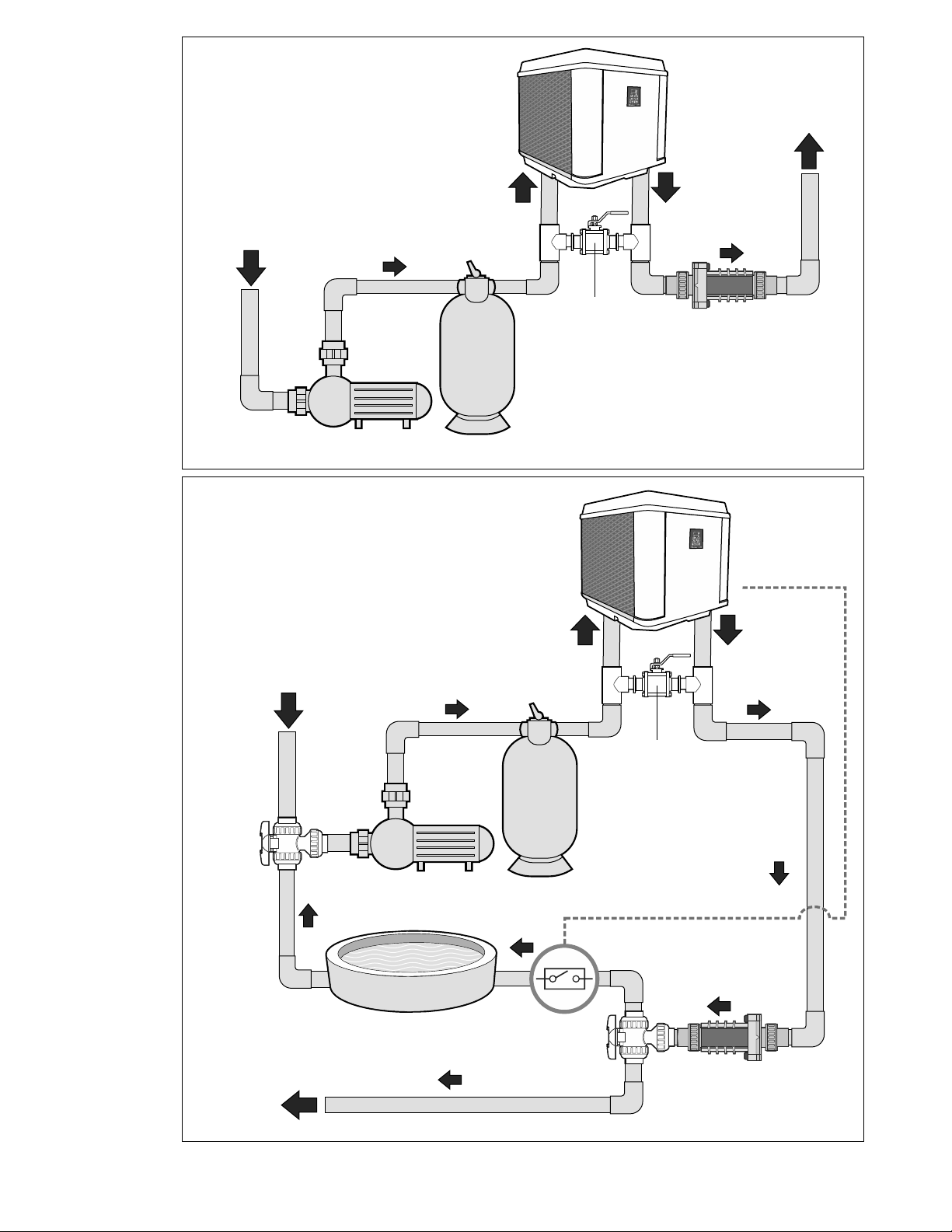
MAINTENANCE
Protecting your Heater
• Keep your pool filter system clean and free of restrictions to ensure proper water flow
• Check water chemistry regularly. Misuse of chemicals will cause permanent damage to
your heater and other pool equipment. Manufacturers can void warranties for damage as
a result of poor water quality.
• Free airflow is essential. Keep the evaporator coil clean and free of weeds, leaves, grass
clippings, dirt and other debris that will decrease the airflow. Keep fences and shrubs
away from air inlets (sides and back of heater).
• Frequent rinsing of the evaporator with fresh water will remove build up from its surface
Always spray the coil gently with a regular garden hose being careful not to bend
aluminum fins.
• Regular cleaning of the cabinet will improve its appearance and extend the life of the
finish.
WARNING - DISCONNECT ELECTRICAL POWER TO UNIT BEFORE STARTING ANY
MAINTENANCE TO PREVENT SERIOUS INJURY FROM SHOCK.

10
It is essential that all water within the unit when winterizing your pool equipment.be properly drained
When water freezes, it expands, damaging piping.
• Turn thermostat settings to OFF. Turn filter pump to OFF.
• Turn power to unit OFF (i.e. pull disconnect or turn circuit breaker OFF).
• Disconnect water inlet and outlet unions at the back of the unit. Be careful not to lose
rubber o-rings.
• Flush the heater piping out with fresh water to remove any residual chemicals.
• Use low-pressure air or vacuum to remove water that has accumulated inside the piping
of the heater.
TROUBLESHOOTING CHECKLIST
• Check to see that the electrical power is on. Reset breakers, or replace fuses if necessary.
• Check to be sure the electric control panel is set properly. The desired temperature must
be set above the actual pool or spa temperature for the heater to run.
• Check to make sure the evaporator coil has enough clearance and that there are no
restrictions to its airflow.
• Certain ambient air conditions may cause the heater to go into defrost mode, displayed on
the control panel as “DEF” .
NOTE: IT IS NORMAL FOR WATER TO DRIP FROM THE DRAINHOLES AT THE BASE OF THE
HEATER. THE UNIT PRODUCES CONDENSATION WHEN IT OPERATES.
ANALYZER CODES
FAILURE LOCK-OUT: This feature is for the protection of the heater. If the same failure
occurs three (3) times within an hour, the control will not allow the unit to restart. and shall
display the appropriate code (i.e. “LP3”, “HP3”).The reset to normal conditions can be
accomplished by pressing any button on the control touch pad one time.
“FLO” (Little or No Water Flow)
• The pump is not running.
• The filter is dirty or clogged.
• Shortage of water to pump - air leak.
• Undersized pump.
• Valves not in correct position.
• Filter in backwash mode.
• Water pressure switch needs adjustment, or is defective.
“HPS” (Compressor High Pressure)
• Low water flow to heater.
• Defective high-pressure switch.
WINTERIZING

11
“LPS” (Compressor Low Pressure)
• Evaporator coil dirty.
• Fan motor not running.
• Low refrigerant pressure.
• Defective low-pressure switch.
• Low ambient air temperature.
“ESO”
• Evaporator temperature sensor connection opened. Check for cut or loose sensor wiring
or defective sensor.
“tSO”
• Water temperature sensor connection opened. Check for cut or loose sensor wiring or
defective sensor.
“ESS”
• Evaporator temperature sensor connection shorted. Check for a short in sensor wiring or
defective sensor.
“tSS”
• Water temperature sensor connection shorted. Check for a short in sensor wiring or
defective sensor.
“DEF”
• Heat pump in defrost cycle.
• Please eliminate any water flow problems before calling for service.
• If you are unable to contact the installing agent, please contact AQUACOMFORT.COM
A factory representative will assist you or your serviceman o ver the phone.
SERVICE PERFORMED WITHIN THE WARRANTY PERIOD MUST BE APPROVED BY AQUACOMFORT
PRIOR TO SERVICE BEING PERFORMED AND ONLY BY AN AWG AUTHORIZED TECHNICIAN.
SEE WARRANTY FOR DETAILS.
Please have the following ready before calling:
MODEL #:
SERIAL #:
DATE OF INSTALLATION:
NAME OF OWNER:
ADDRESS:
CONTACT # :
NATURE OF PROBLEM:
ANALYZER CODES (Cont.)
CALLING FOR SERVICE
888-475-7443

SWIMSMART HEAT PUMPS
BY AWG
888-475-7443 (HEAT)
This manual suits for next models
2
Table of contents
Other AWG Heat Pump manuals
Popular Heat Pump manuals by other brands

HIdRos
HIdRos LZT P4U Series Technical manual

Aqua
Aqua PH Series Installation and instruction manual

REMKO
REMKO WKF-Compact Series Assembly and operating instructions

Carrier
Carrier Infinity 50XT Product data

Daikin
Daikin EHYHBH05AA User reference guide

Harmopool
Harmopool Harmo POWERPACK Series instruction manual

Beretta
Beretta Power Plus Box 150 installation manual

LG
LG MULTI V LRNN-BE Series installation manual

Danfoss
Danfoss OPTYMA Plus Series manual

emmeti
emmeti WILO-PARA P2 ITM 200 Installation and use manual

Carrier
Carrier COMFORT SERIES 25HCC5 Installation instructions manual

Bryant
Bryant CH17NA installation instructions