Rockler Material Mate User manual

Material Mate™
Instructions

2
>For any tool used in conjunction with this product,
always read, understand and follow the instructions
and safety warnings for that tool.
>Before using this product, review and verify that all
tools to be used with it have safety equipment
installed and are in proper working order as
definedbythetools’owner’smanuals.
>Do not use this product until you have read and
are confident you understand the:
• Product Specific Safety Warnings (below);
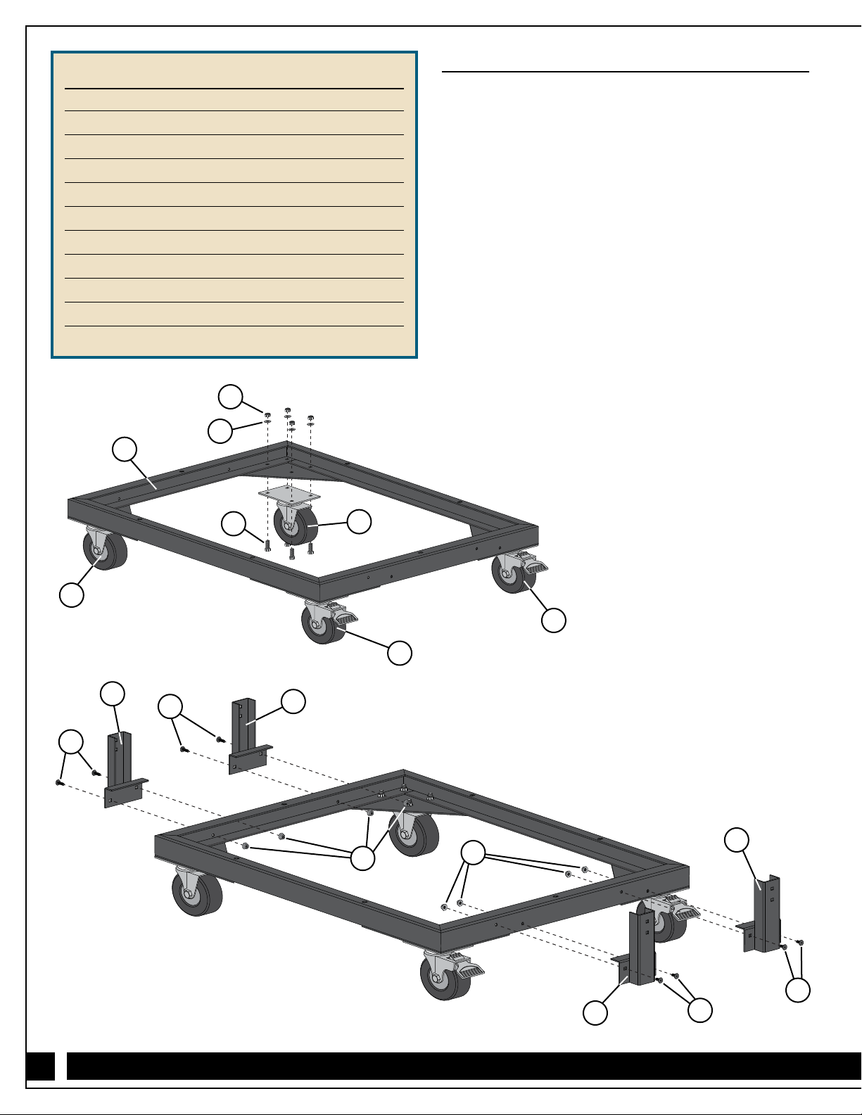
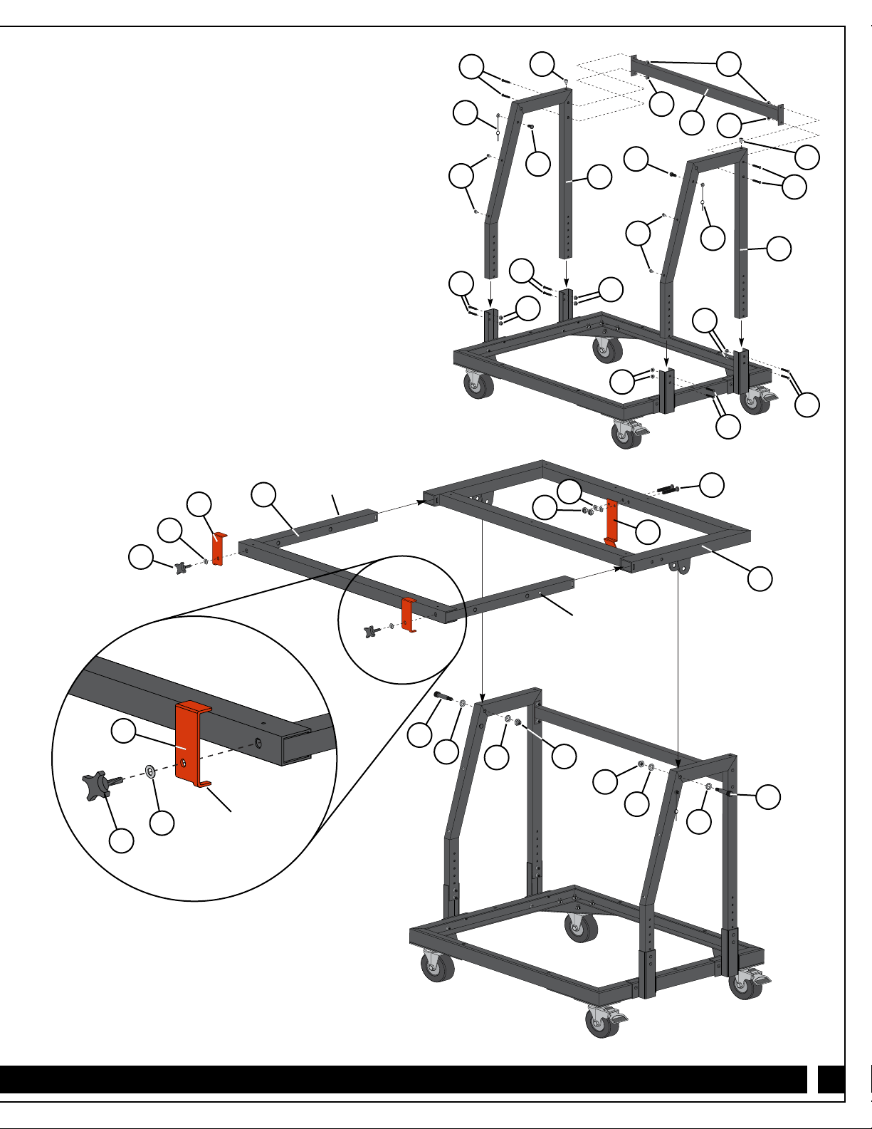
• Material Mate™Assembly (pp. 4-6);
• Material Mate™Loading (p. 6);
• Lifting the Sheet Upright (p. 7);
• Transporting the Sheet (p.7);
• Unloading the Material (pp. 7-8);
• Postioning the Material at the Table Saw (p. 8);
• Using as a Work Table (p. 8).
>Remain alert and use good judgment when using
this tool. Do not use this tool if you are in any way
impaired by medications, alcohol, drugs or fatigue.
>Dress appropriately and remove all jewelry, secure
loose clothing and tie up long hair before using
this tool.
>It is the sole responsibility of the purchaser of this tool
to ensure that any third party reads and complies with
all the instructions and safety precautions outlined in
this manual prior to using the tool.
>Maintain these instructions and warnings as long as
you own the tool. Keep this booklet in a place where
it will be readily available for reference.
>The user assumes all risk for the proper use of
this tool and for ensuring product suitability for
intended application.
>Always wear safety glasses in compliance with ANSI
safety standards and hearing protection and follow all
standard shop safety practices, including:
•Keep your work area well lit and clean;
•Use dust collection tools and dust face masks to
reduce exposure to dust;
•Use accessory safety equipment such as
featherboards, push sticks and push blocks
whenever appropriate;
•Do not use power tools in explosive
environments (e.g., in the presence of
flammable liquids, fumes or dust);
•Keep children and bystanders away while
operating your tools;
•Maintain proper footing at all times and
do not overreach;
•Do not force the tool;
•Unplug all power tools before making any
adjustments or changing accessories.
>These warnings and instructions do not represent the
total of all information available regarding tool safety,
use and technique. Always seek out opportunities to
learn more and improve your skills and knowledge.
This tool is designed for specific applications as defined in the instructions and should not be modified and/or used
for any other applications. Before using the Material Mate™, read, understand and follow all instructions and safety
information provided. KEEP THESE INSTRUCTIONS FOR FUTURE REFERENCE.
GENERAL SAFETY WARNINGS
>Load is not secured when in vertical position. Do not
attempt to machine or otherwise work on the material
in any way while it is upright on the cart.
>Make sure Material Mate™is assembled so that its
height, when flat, is 1/2" below the surface of the
table saw. This includes any top attached to the
Material Mate™.
>Table Extension (21) is not locked when in the
upright position and could unexpectedly tip back to
horizontal position if downward pressure is
inadvertently applied.
>Do not load sheet goods onto the Material Mate™on
slanted or uneven ground or the cart could move or
tip. Only load on level ground.
>Never feed sheet directly from the Material Mate™into
the table saw. Transfer sheet to table saw first, before
turning on saw.
>Make sure that there is proper outfeed support for the
material as it leaves the table saw.
PRODUCT SPECIFIC SAFETY WARNINGS

3
Quantity
1 1/4" Lock Nut 18
2 1/4" Washer 18
3 1/4" x 3/4" Hex Bolt 16
4 1/4" Flange Nut 20
5 1/4" x 5/8" Bolt 8
6 1/4" x 11⁄2" Bolt 12
7 1/4" x 1/2" Bolt 2
8 Safety Locking Pin 2
PARTS LIST Quantity
9 Rubber Bumper 6
10 4-Star Knob 2
11 1/4" x 2" Bolt 2
12 Shoulder Bolt 2
13 1/2" Washer 4
14 3/8" Lock Nut 2
15 3/8" Washer 2
6
4
11
2
1
13
9
12
14
8
7
15
5
10
3

4
Quantity
16 Base 1
17 Locking Caster 2
18 Caster 2
19 Leg Support 4
20 Vertical Support 2
21 Crossbar 1
22 Frame Assembly 1
23 Table Extension 1
24 Left Flip Stop 1
25 Right Flip Stop 1
26 Latch Arm 1
PARTS LIST Material Mate™Assembly
1. Attach the two Casters (18) and two Locking Casters (17)
to the Base (16) with 1/4" x 3/4" Hex Bolts (3), 1/4"
Washers (2) and 1/4" Lock Nuts (1). Fig. 1.
Make sure to install the casters in the orientation
shown — the Locking Casters (17) must be installed on
the same end of the base so they are side by side.
2. Attach the four Leg Supports (19) to the Base (16) with
1/4" x 5/8" Bolts (5) and 1/4" Flange Nuts (4). Fig. 2.
3. Slide the Vertical Supports (20) into the Leg Supports (19),
aligning the bottom set of holes in the Vertical Supports
with the holes in the Leg Supports, and secure with
1/4" x 11⁄2" Bolts (6) and 1/4" Flange Nuts (4). Fig. 3.
You will need to adjust the height setting in a later step.
4. Position the Crossbar (21) between the Vertical Supports (20)
and attach with 1/4" x 11⁄2" Bolts (6) and 1/4" Flange
Nuts (4). Fig. 3.
5. Attach a Safety Locking Pin (8) to the outside face of each
Vertical Support (20) with a 1/4" x 1/2" Bolt (7) threaded into
the integral nut in the support. Fig 3.
Fig. 1 - Base Assembly
Fig. 2 - Leg Support Assembly
1
2
16
18
3
17
17
519
5
19
5
5
19
19
18
44

5
Fig. 4 - Arm and Top Assembly
Fig. 3 - Vertical
Support Assembly
6. Press the Rubber Bumpers (9) into the appropriate holes
on the angled faces of the Vertical Supports (20). Fig. 3.
7. Slide the Table Extension (23) into the Frame Assembly (22),
depressing the bullet pins in the Table Extension (23) to
allow it to fully insert. Fig. 4.
8. Attach the Left and Right Flip Stops (24 and 25) at the
appropriate locations on the Table Extension (23) with 4-Star
Knobs (10) and 3/8" Washers (15). The small tabs at the
bottom of the Flip Stops should be oriented toward the
outside edge of the assembly. Fig. 4.
9. Attach the Latch Arm (26) to the back of the Frame
Assembly (22) with 1/4" x 2" Bolts (11), 1/4" Washers (2)
and 1/4" Lock Nuts (1). Fig. 4.
10. Set the Frame Assembly (22) on the Vertical Supports (20),
aligning the holes in the downward tabs of the frame with
the holes at the top of the supports. Attach with Shoulder
Bolts (12), 1/2" Washers (13; these go on the outside of the
tabs) and 3/8" Lock Nuts (14). Fig. 4.
6
8
97
4
4
21 4
7
9
20
20
6
8
4
6
6
4
4
6
6
4
22
24 23
10
12
13 13 14
14
13
13
12
10
25
Tab should point to
the outside edge of
the assembly
Bullet Pin
Bullet Pin
15 26
2
1
11
15
9
9

6
1. Position the Material Mate™far enough from your vehicle
so you will be able to center the sheet on the cart
during unloading.
2. Engage the Locking Casters (17) and rotate the Flip
Stops (24 and 25) on the Table Extension (23) to the side
so they are parallel to the Table Extension (23) and tighten
the 4-Star Knobs (10). Fig. 6.
3. Make sure the Latch Arm (26) is fully engaged to keep the
top secure in a horizontal position and to prevent it from
inadvertently tipping upright. Fig. 7.
To avoid accidental Vertical tilting and
unintended movement of the materials,Latch Arm (26)
must be fully engaged (“clicked” to hold together the
Frame Assembly (22) and Crossbar (21))
4. Pull the Safety Locking Pins (8) from the Vertical
Supports (20) and depress the bullet pins to pull the
Table Extension (23) outward. Continue to pull the Table
Extension (23) until the pins re-engage. The Locking
Pins must be re-inserted to secure the Table Extension (23)
in place. Fig. 8.
5. Pull the sheet of material onto the Material Mate™and center
it on the cart.
6. Adjust the position of the sheet material until the long
edge nearest the Table Extension (23) is flush with
the Table Extension (23).
7. Rotate the Flip Stops (24 and 25) up and secure in place by
tightening the 4-Star Knobs (10). Failure to secure the knobs
could allow potentially dangerous shifting of the material
during transport. Fig. 9.
8. Make sure the sheet remains centered on the cart, both front
to back and side to side. Off-center positioning could cause
the load to become unstable or the cart to tip.
11. Adjust the height of the Material Mate™cart by removing the
1/4" x 11⁄2" Bolts (6) and 1/4" Flange Nuts (4) holding
the Vertical Supports (20) to the Leg Supports (19) and
reattaching using the sets of holes that produce the proper
height. The Material Mate™must be assembled so that its
height, when the Frame Assembly is flat, is at least 1/2"
below the surface of the table saw. This includes any top
attached to the Material Mate™. Fig. 5.
Material Mate Loading
>Overloading cart will cause tipping and potential
injury. Do not load more than one sheet of 3/4"
thick (max.) material at a time.
WARNING
Fig. 7
Fig. 6
Fig. 5
>Do not attempt to lift more than you are
physically able. Get help if necessary. Use
proper lifting techniques.
CAUTION
Table Saw Material Mate
1/2" minimum
25
23
24
26
21
22

7
1. Holding the material securely, release the Locking
Casters (27).
2. With one hand on the material and one hand on the cart,
carefully push the cart to its destination, paying close
attention to the terrain in front of the cart. Fig. 11.
Unloading Material
1. Make sure the cart is on a flat, level surface. The cart could
move or tip or the load could become unstable if unloaded on
uneven terrain.
>Take special care and go slowly when moving
across uneven surfaces such as a door threshold;
material could shift or become unstable
during transport.
CAUTION
Lifting the Sheet Upright
1. Position yourself on the side of the sheet opposite the
Flip Stops (24 and 25).
2. Holding the sheet securely, reach underneath and release the
Latch Arm (26).
Flip Stops (24 and 25) must be rotated up
and secured by tightening the 4-Star Knobs (10) before the
sheet can be safely tilted upright. Load will fall when tilted
unless Flip Stops (24 and 25) are engaged. Fig. 9.
Keep hands clear of the pivot point to avoid
pinching fingers.
3. With sheet positioned against the Flip Stops (24 and 25)
slowly allow the sheet to tip upright, maintaining a secure
hold until the sheet stops moving and you’re sure the load
is stable on the cart. Fig. 10.
Transporting the Sheet
Fig. 11
Fig. 9
Fig. 8
Fig. 10
Bullet Pin
8
25
24
23

1. Position the cart so that, when sheet is tipped to the
horizontal position, the leading edge of the sheet will be
near but not on the saw’s table. Engage the Locking
Casters (17). Fig. 12.
2. With the saw turned off, verify that the cart is positioned
correctly. Holding the sheet with both hands, carefully tip it
and guide it to the horizontal position. Keep your hands clear
of the cart to avoid pinching your fingers, and make sure the
Latch Arm (26) engages against Crossbar (21) with a “click”
to keep table in horizontal position.
3. If necessary, adjust the cart position by carefully tilting the
sheet back upright, unlocking the casters and moving the
cart. Repeat Steps 2-3 until optimal position is achieved.
Engage the Locking Casters (17).
4. Holding the sheet with both hands, carefully slide it off the
cart so one corner is on the edge of the table saw. Fig. 13.
5. Turn on the saw.
6. Make sure there is proper outfeed support for the material
when it leaves the table saw.
7. Advance the material into the blade, keeping the edge tight
against the fence. If necessary, use a push stick at the end of
the cut to keep your hands away from the blade.
Check Rockler.com for updates. If you have further questions, please
contact our Technical Support Department at 1-800-260-9663
or support@rockler.com
8Distributed by Rockler Companies, Inc.
©2016 Rockler Woodworking and Hardware
56889
Rev 12/16
>The Table Extension (23) must be retracted and
secured if the Material Mate™is to be used as a
worktable. Use of the Material Mate™as a table
with the Table Extension (23) extended creates
a tipping hazard. Make sure bullet pins and Safety
Locking Pin (8) are fully engaged.
CAUTION
>Never feed sheet directly from the Material Mate™
into the table saw. This can cause kickback and
injury. Transfer sheet to table saw before turning
on saw.
WARNING
Sliding sheets off the cart while in the
upright position could cause the cart to tip, resulting in
injury or property damage. Only unload when table frame
is in a horizontal position.
2. Engage the Locking Casters (17).
3. Lift the sheet above the Flip Stops (24 and 26) and
off the cart.
Positioning the Material at a Table Saw
Using as a Worktable
1. Attach a top and narrow extension strip to the Material
Mate™by driving screws (not included) through predrilled
holes in the frame. Fig. 14.
Maximum thickness for a top is 3/4". If a
top is attached, a narrower strip of equal thickness must
be attached separately to the Table Extension (23). Fig. 14.
This is necessary to maintain an even surface for stable
handling of sheet goods.
Fig. 14
Fig. 12
Fig. 13
Material
Mate
Table
Saw
Sheet
Narrow strip
23
Table of contents
Popular Outdoor Cart manuals by other brands

Oskar-Bebehut
Oskar-Bebehut BT-504S Owner's instruction and safety manual

International
International INT33CART4GRN Use and care guide

VYPER
VYPER ROBUST STEEL SPORT Assembly guide

Husky
Husky WHEEL BARROW 1006456732 instruction manual

DR
DR SUBURBANTM Safety & Operating Instructions

Jaco
Jaco Ultralite Power Blade Hot-Swap 300 Series manual