Rockwell Allen-Bradley VersaView 6300B User manual

Installation Instructions
Original Instructions
VersaView 6300B Box PCs and 6300T Box Thin Clients
Bulletin Numbers 6300B-BMAx, 6300B-BMBx, 6300B-BMFx, 6300B-DRFx, 6300T-BAx1
Summary of Changes
This publication contains the following new or updated information. This list includes substantive updates only and is not intended to reflect all changes. Translated versions are not
always available for each revision.
Environment and Enclosure Information
UL/cUL Mark Compliance
Equipment with the UL/cUL mark complies with the requirements of UL 61010-1, UL 61010-2-201, CSA C22.2 No. 61010-1, and CSA C22.2 No. 61010-2-201. A copy of the certificate of
compliance is available at rok.auto/certifications.
European Union Directive Compliance
This equipment meets the European Union Directive requirements when installed within the European Union or EEA regions and have the CE marking. A copy of the declaration of the
conformity is available at rok.auto/certifications.
Topic Page
Removed ‘book mount’ from publication title and wherever used in publication. Throughout
Added the Important table to Required Tools and Hardware for Installation section. 2
Changed from 2.5 mm Phillips screwdriver to #2 Phillips screwdriver in Required Tools and Hardware for Installation section. 2
Expanded dimensional drawings into Figure 1 and added the following:
• Dimensional drawings and callouts for the 6300B-BMFxand 6300B-DRFxbox PCs
• Any missing English unit equivalents for the 6300B-BMAxbox PCs, 6300T-BAx1 thin clients, and 6300B-BMBxBox PCs
• Overall depth dimension for the 6300B-BMBxBox PCs
• Revised the callout title from ‘6300B-BMAxand 6300T-BAx1 Box PCs’ to ‘6300B-BMAxBox PCs and 6300T-BAx1 Box Thin Clients’
2
Added the Install a Box PC With the DIN Rail Bracket section. 2
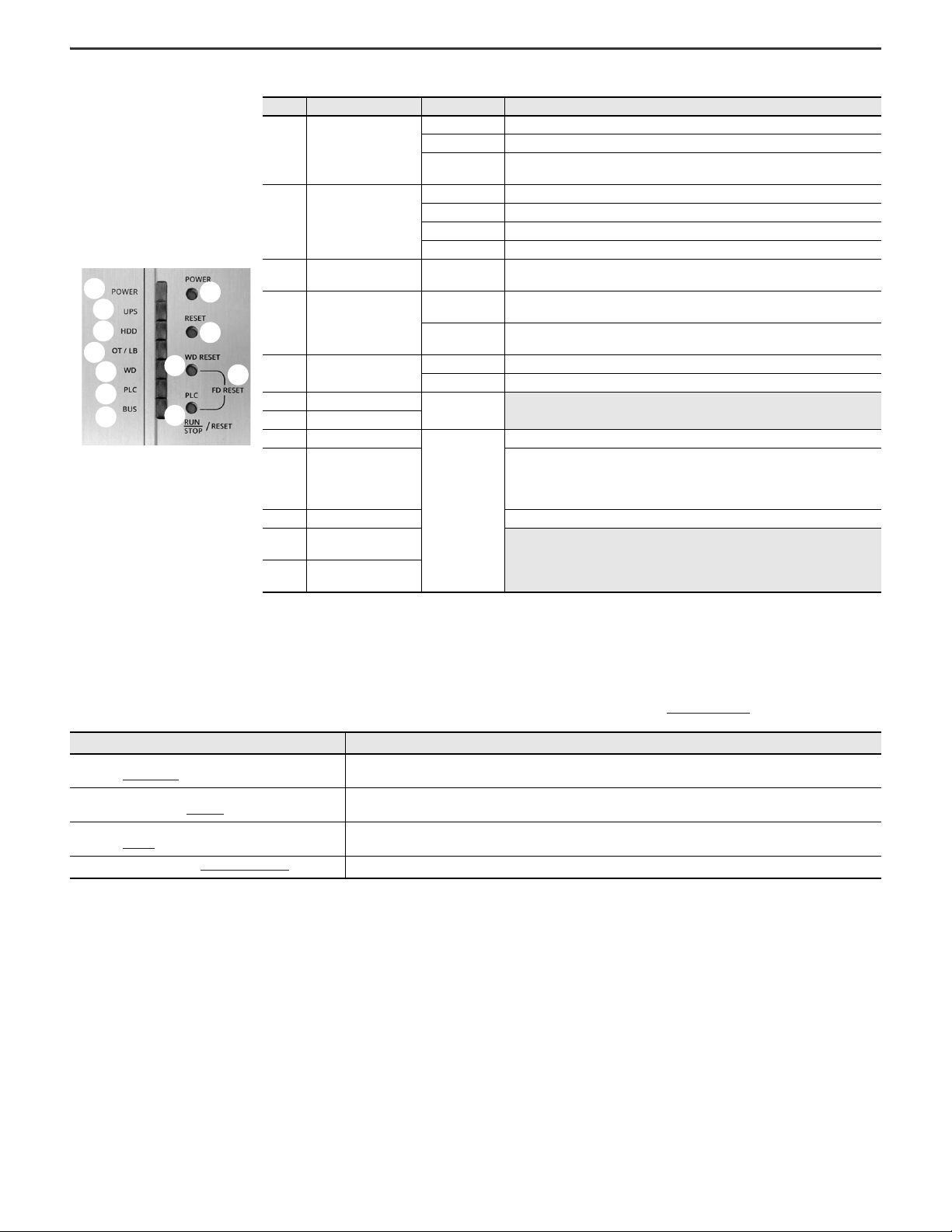
Added the following to the Connect Peripherals section:
• The picture for 6300B-BMFxand 6300B-DRFxmodels
• The digital input/output (I/O) item to the picture and table
• The USB cable length stipulation
4
Changed the heading from ‘Connect DC Power’ to ‘Connect DC Power Wiring.’ 4
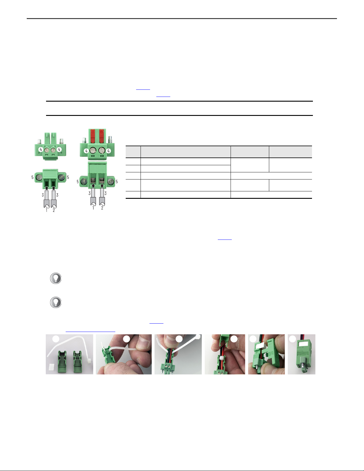
Added the subheading ‘For 6300B-BMAxand 6300B-BMBxBox PCs, and 6300T-BAx1 Box Thin Clients’ to the Install the DC Connector Assembly section. 5
Added the For 6300B-BMFxand 6300B-DRFxBox PCs subsection. 6
Added the Connect DC Power section. 6
Expanded the Table 1 title to include 6300B-BMFxand 6300B-DRFxBox PCs. 6
ATTENTION: This equipment is intended for use in a Pollution Degree 2 industrial environment, in overvoltage Category II applications (as defined in
IEC 60664-1), at altitudes up to 2000 m (6561 ft) without derating.
This equipment is considered Group 1, Class A industrial equipment according to IEC/EN 61326-1. Without appropriate precautions, there can be potential
difficulties with electromagnetic compatibility in other environments due to conducted as well as radiated disturbance.
This equipment is considered open equipment, which means it must be mounted in an enclosure where the equipment can be operated from the front panel.
The enclosure in which this equipment is installed must be accessed only with a key or tool, and only by trained and authorized personnel.
In addition to this publication, see the following:
• Industrial Automation Wiring and Grounding Guidelines, publication 1770-4.1, for more installation requirements
• UL 50, CSA C22.2 No. 94.1, and IEC 60529, as applicable, for explanations of the degrees of protection provided by enclosures
ATTENTION: This equipment is intended to operate in an industrial or control room environment, which uses some form of power isolation from the public
low-voltage mains. Some computer configurations cannot comply with the EN 61000-3-2 Harmonic Emissions standard as specified by the EMC Directive of
the European Union.
All I/O cables must be used only indoors.

2Rockwell Automation Publication 6300B-IN001C-EN-P - February 2021
VersaView 6300B Box PCs and 6300T Box Thin Clients Installation Instructions
Installation Guidelines
Follow these guidelines to make sure that your VersaView® 6300B box PC or VersaView 6300T box thin client provides service with excellent reliability.
• When choosing the installation site, consider the following:
- The site must have sufficient power
- The site must be indoors and non-hazardous
- The site must not expose the computer to direct sunlight
• The box PC or box thin client can operate in a surrounding air temperature range as follows:
- 0…55 °C (32…131 °F) with the Intel Atom x5 processor
- 0…50 °C (32…122 °F) with the Intel Atom x7 processor
- 0…50 °C (32…122 °F) with the Intel Core i3, Core i5, and Core i7 processors
The surrounding air temperature must not exceed the maximum temperature for your box PC or box thin client, especially when either one is mounted in an enclosure.
• The box PC or box thin client can be stored in a surrounding air temperature range of -10…+60 °C (14…140 °F).
• The humidity of the surrounding air must not exceed 80% noncondensing.
Mounting Requirements
Follow these requirements to mount the VersaView 6300B box PCs or VersaView 6300T box thin clients.
• Choose a suitable mounting height.
• Only mount the box PC or box thin client in a vertical (upright) position, where the ground screw is at the bottom, as shown in Figure 1 on page 3.
• Mount the box PC or box thin client so there is at least 20 mm (0.8 in.) of clearance on each side for the circulation necessary for cooling.
Required Tools and Hardware for Installation
The following tools are needed for the mounting bracket installations.
• A drill and 4 mm drill bit
• #2 Phillips screwdriver
• Four M4x20 stainless steel screws (customer supplied)
•Safetyglasses
Install a Box PC or Box Thin Client With the Book Mount Bracket
Install the box PC or box thin client in an industrial or control room environment, which uses some form of power isolation from the public, low voltage mains.
1. Use the dimensions in Figure 1 on page 3 to locate and drill holes for the four M4x20 stainless steel screws.
2. Install the four customer-supplied screws but leave enough space to hang the brackets.
3. Align the keyhole slots on the top bracket with the top two screws.
4. Align the slots on the bottom bracket with the bottom two screws.
5. Slide the computer downward until all four screws are at the top of each bracket slot.
6. Tighten the four screws.
Install a Box PC With the DIN Rail Bracket
Install the box PC in an industrial or control room environment, which uses some form of power isolation from the public, low voltage mains.
1. Refer to the 6300B-DRFxBox PC dimensions in Figure 1 on page 3.
2. Install the box PC on a DIN rail.
ATTENTION: For DIN rail mounting applications, only safety glasses are needed.
IMPORTANT A DIN rail is not supplied with the bracket. An installed DIN rail is the responsibility of the customer.

Rockwell Automation Publication 6300B-IN001C-EN-P - February 2021 3
VersaView 6300B Box PCs and 6300T Box Thin Clients Installation Instructions
Figure 1 - 6300B Box PCs and 6300T Box Thin Clients Dimensions
39.4
(1.55)
4.5
(0.18)
127.5
(5.02)
8 (0.31)
20
(0.79)
100 (3.94)
8 (0.31) 36 (1.42)
100
(3.94)
8
(0.31)
20
(0.79)
4 x Ø 4
(1.8)
All dimensions are in mm (in.).
All illustrations are not-to-scale.
Front View
Vertical (Upright) Position Side View
19
(0.75)
230
(9.06)
19
(0.75)
6
(0.24)
4 x Ø 4 (1.8)
25 (0.98)
25 (0.98) 100 (3.97)
150 (5.9) 5.5
(0.22)
100 (3.97)
150 (5.9)
256.5
(10.1)
268
(10.6)
Front View
Vertical (Upright) Position Side View
6300B-BMAxBox PCs and 6300T-BAx1 Box Thin Clients
6300B-BMBxBox PCs
221 (8.7)
6300B-BMFxBox PCs
47 (1.85)
4.5
(0.18)
127.25
(5.01) 140
(5.51)
20 (0.79)
100 (3.94)
8.25
(0.32) 77 (3.03)
100
(3.94)
20 (0.79)
4 x Ø 4.5
(0.18)
Front View
Vertical (Upright) Position Side View
6300B-DRFxBox PCs
Front View
Vertical (Upright) Position Side View
79 (3.11)
20
(0.79)
100 (3.94)
100
(3.94)
50 (1.97)
23 (0.9)
100
(3.94)
27 (1.06)
47 (1.85)
15 (0.6) 2 (0.08)
2 (0.08)
26
(1.02) 26
(1.02) 8.5 (0.33)
1.5
(0.06)
4 (0.16)
15
(0.6)

4Rockwell Automation Publication 6300B-IN001C-EN-P - February 2021
VersaView 6300B Box PCs and 6300T Box Thin Clients Installation Instructions
Connect Peripheral Cables
Connect peripheral cables to the appropriate I/O ports on the computer. To comply with
EN 61326-1, use the following for cable types. All I/O cables must be used only indoors, and
USB cables must be less than 3 m (9.84 ft) long.
Grounding and Bonding
Whenever two connected pieces of equipment are far apart, it is possible that their ground
connections could be at a different potential level.
To overcome these possible grounding problems, the following bonding methods are
recommended:
• Method 1: Connect the data cable shields to the equipotential bonding rail on both
sides before connecting the cable to the interfaces.
• Method 2: Use an equipotential bonding cable (16 mm2or 6 AWG) to connect the
grounds between this VersaView 6300B box PC or 6300T box thin client and a
connected monitor.
DC Power Supply Guidelines
Follow these guidelines to select the DC power supply for the computer.
• The computer must be powered with a voltage of 24V DC (18…32V DC).
• The nominal output power must be 25% larger than the drained power.
• The output voltage rise time has to be less than 100 ms.
• Consider the working temperature and the thermal derating of the power supply.
• The inrush current cannot exceed a peak current of 10 A and a pulse width time of 400 µs.
Connect DC Power Wiring
Follow these steps to connect the box PC or box thin client to a DC power source.
Install the Ground Wire
1. Turn off the main power switch or breaker.
2. Remove the supplied nut, eyelet terminal, and washers from the ground screw.
3. For earth ground, fasten a 2.5 mm2(14 AWG) or larger external wire to the eyelet terminal.
Use a ground wire with an insulation color that is approved by local inspection authority.
4. Install the ground wire to the ground screw in the sequence at right.
5. Tighten the nut to the ground screw.
6. Proceed to Install the Factory-supplied DC Power Connector Assembly on page 5.
Item
No. Cable Type
Required
Attribute
Item
No. Cable Type
Required
Attribute
1LAN
Shielded
6DVI-D
Shielded
2USB3.0
(1)
(1) The front of 6300B-BMBx models includes another USB 3.0 port.
7RVL
(2)
(2) Remote Video Link, which is a future option.
3USB2.0 8DigitalI/O
4 RS-232 DB9M 9 DC power Unshielded
5 DisplayPort 10 UPS connection(3)
(3) Uninterruptible Power Source, which is a future option.
ATTENTION: Supply the box PC or box thin client with its own disconnect. On models with an available connection, use an uninterruptible
power source (UPS) to help protect against unexpected power failure or power surges.
You need the following tools for this installation:
•Smallscrewdriver
• Wire stripper, cutter, and crimper tool
•Cuttingpliers
17
6
4
9
7
1
1
2
5
3
2
1
1
9
Front of
6300B-BMAxand 6300T-BAx1 models
Top of 6300B-BMBxmodels
10
9
10 1
1
1
1
2
2
Front of
6300B-BMFxand 6300B-DRFxmodels
4
5
8
12345
Sequence No. Description Sequence No. Description
1 Toothed washer 4 Lock washer
2 Eyelet terminal 5 Nut
3Washer

Rockwell Automation Publication 6300B-IN001C-EN-P - February 2021 5
VersaView 6300B Box PCs and 6300T Box Thin Clients Installation Instructions
Install the Factory-supplied DC Power Connector Assembly
For 6300B-BMAx and 6300B-BMBx Box PCs, and 6300T-BAx1 Box Thin Clients
This connector assembly provides strain relief for the DC power wires by reducing their movement. To assemble and attach the connector assembly, perform the following steps.
1. Remove the DC terminal block from the computer chassis.
2. Open the power connector assembly kit that ships with the computer (A).
3. Insert the cable tie through the slots of the appropriate connector half (B).
4. Strip the end of each DC power wire to the length in Figure 2.
5. Insert each stripped end into the DC terminal block as shown in Figure 2.
Figure 2 - DC Terminal Block Connection Specifications
6. Tighten the screws on top of the terminal block to secure the DC power wires to the torque value in Figure 2.
7. Slide the connector half with the attached tie onto the end of the DC terminal block (C).
8. Tighten the cable tie so it is snug against the terminal wires.
9. Use cutting pliers to cut the excess part of the cable tie (D).
10. Install the white label supplied with the kit (E).
11. Align and install the other connector clamp half to complete the assembly (F).
12. Reconnect the DC terminal block with the connector assembly to the computer chassis.
Torque the DC terminal block flange screws to the values in Figure 2.
13. Proceed to Connect DC Power on page 6.
IMPORTANT The DC terminal block in the photos is only for illustrative purposes. Your DC terminal block can differ in size, shape, and color to
what is shown in the photos.
The white label can be used for identification or other information.
When installed correctly, both tabs of the clamp half lock into place.
Item Description
6300B-BMAx and
6300T-BAx1 Models 6300B-BMBx Models
1 DC+ (24V DC nominal) recommended power wire size(1)
(1) DC power wires must be of stranded copper and certified for at least 85 °C operation.
1.5 mm2(16 AWG) 2.5 mm2(14 AWG)
2 DC- (0V DC) recommended power wire size(1)
3 Stripped wire length 7 mm (0.275)
4 Torque range to secure DC power wires 0.22...0.25 N•m
(0.16...0.18 ft•lb) 0.5...0.6 N•m
(0.37...0.4 ft•lb)
5 Torque value to reinstall DC terminal block to computer 0.3 N•m (0.22 ft•lb)
DC Terminal Block for
Cat. Nos. 6300-BMAx
and 6300T-BAx1 Models
DC Terminal Block for
Cat. No. 6300-BMBx Models
DA B C E F

6Rockwell Automation Publication 6300B-IN001C-EN-P - February 2021
VersaView 6300B Box PCs and 6300T Box Thin Clients Installation Instructions
For 6300B-BMFx and 6300B-DRFx Box PCs
To assemble and attach the connector assembly, perform the following steps.
1. Remove the DC terminal block from the computer chassis.
2. Strip 10 mm (0.4 in.) from the end of four different-colored wires.
3. Press the spring connection tabs on the DC terminal block, and insert each
stripped end of wire according to the following table.
4. Release the spring connection tabs after the stripped end of each wire has been
fully inserted in the appropriate terminal connection.
5. Reconnect the DC terminal block to the computer chassis.
Torque the DC terminal block flange screws to 0.3 N•m (0.22 ft•lb).
6. Proceed to Connect DC Power.
Connect DC Power
All VersaView DC powered models require a safety extra low voltage (SELV) power supply. The internal power supply is protected against reverse polarity.
To minimize ground loop currents and noise, Allen-Bradley® recommends that DC powered models use only one grounded connection. See Install the Ground Wire on page 4 for the
ground connection on these models.
Computer Light-emitting Diode and Button Descriptions
Once power is supplied to the computer, light-emitting diodes (LEDs) signify the following.
IMPORTANT Use stranded copper wire sized 1.5 mm2(16 AWG)
and certified for at least 85 °C operation.
ATTENTION: When you connect power to the box PC or box thin client for the first time, these actions occur:
• The default UEFI setting automatically starts the computer after it is plugged into a power source.
• For VersaView 6300B box PCs with a Microsoft Windows® operating system (OS), you must read and accept an End User Setup procedure.
Do not disconnect power from the system until after the Windows Setup procedure is completed. If power is disconnected during this
procedure, it can result in a corrupted system image.
Table 1 - LEDs and Buttons on the Front Panel of VersaView 6300B-BMAx, 6300B-BMFx, and 6300B-DRFxBox PCs, and VersaView 6300T-BAx1 Box Thin Clients
No. Description Color Power Status
1Standby/poweronLED
No color The computer is powered off.
Green The computer is powered on.
Yellow The computer is safe to power off; the operating system has been shut down
successfully(1).
(1) Microsoft Windows operating systems are not installed on VersaView 6300T thin client models.
Flashing green The computer is in a low-power state; the current session information is being stored in its
RAM.
2 Mass storage LED Yellow When lit, access to a mass storage device (SSD or CF) is happening through a SATA
channel.
3WatchdogLED Green The watchdog is working.
Red The watchdog timer has expired.
4Thermal alarm/
low battery LED
Red A thermal sensor on the motherboard near the CPU has exceeded the thermal limit of
85 °C (185 °F).
Flashing red The clock battery power is below 2.5V; consider replacing. At 2V, data and time loss is
possible.
5 Power/system reset button — For the main reset of the system. Press this button once to restart the computer and reset
the system state.
6 Watchdog reset button — Press this button once to reset the watchdog error LED.
Item Abbreviation Function
1 + + Input voltage (fused)
2—-Inputvoltage
3SYSOFFSystemOFFinput
4 PS Power status output (0.5 A limited)
3
2
1
4
1 2
3 4
1
2
3
4
5
6

Rockwell Automation Publication 6300B-IN001C-EN-P - February 2021 7
VersaView 6300B Box PCs and 6300T Box Thin Clients Installation Instructions
Additional Resources
This publication provides basic installation instructions. For more information, see the following Rockwell Automation publications at rok.auto/literature.
Table 2 - LEDs and Buttons on the Front Panel of VersaView 6300B-BMBxBox PCs(1)
No. Description Color Function
1 Power on LED
No color The computer is powered off.
Green The computer is powered on.
Yellow The computer is safe to power off; the operating system has been shut down
successfully.
2 UPS LED (optional item)
No color No uninterruptible power supply (UPS) battery pack is installed.
Green The computer is powered by an external 24V DC source.
Yellow The UPS battery pack is disconnected.
Flashing green The external 24V DC source is lost, and the computer is powered by the UPS.
3 Mass storage LED Yellow When lit, access to a mass storage device (SSD or CFast) is happening through a
SATA channel.
4Thermal alarm/
low battery LED
Red A thermal sensor on the motherboard near the CPU has exceeded the thermal limit
of 85 °C (185 °F).
Flashing red The real-time clock (RTC) battery is lower than 2.5V. Replace before the battery
goes lower and risks loss of date and time.
5WatchdogLED Green The watchdog is working.
Red The watchdog timer has expired.
6 PLC status LED(2)
—
7BUSstatusLED
(2)
8 Power on reset button
—
Turns the computer on or off.
9 System reset button
Forces an internal reset, as if power was lost temporarily and then returned.
IMPORTANT: Use this button only if there are no better options, like keyboard or
mouse commands. System reset can cause data loss and possible corruption to
the operating system.
10 Watchdog reset button Turns off the watchdog LED (item 5).
11 PLC run/stop/reset
button(3)
12 Factory default reset
button(3)
(1) You must open the front right door to access the buttons that are described in items 8…12.
(2) Not applicable.
(3) Not implemented.
Resource Description
VersaView 6300B Box PC and 6300T Thin Clients User Manual,
publication 6300B-UM001 Provides details on how to install, configure, operate, and troubleshoot the VersaView 6300B book mount box PCs and 6300T book
mount box thin clients.
VersaView 6300 Industrial Computer and Monitor Specifications
Technical Data, publication IC-TD003 Provides technical specifications for VersaView 6300 industrial computers and monitors.
Industrial Automation Wiring and Grounding Guidelines,
publication 1770-4.1 Provides general guidelines to install a Rockwell Automation industrial system.
Product Certifications website, rok.auto/certifications Provides declarations of conformity, certificates, and other certification details.
1
2
3
4
5
6
7
8
9
10
11
12

Publication 6300B-IN001C-EN-P - February 2021 | Supersedes Publication 6300B-IN001B-EN-P-October 2020
Copyright © 2021 Rockwell Automation, Inc. All rights reserved. Printed in Italy.
Vendor Code 80460002.02
DIR 10005614692 (Version 02)
Allen-Bradley, expanding human possibility, Rockwell Automation, and VersaView are trademarks of Rockwell Automation, Inc.
Microsoft and Windows are trademarks of Microsoft Corporation.
Trademarks not belonging to Rockwell Automation are property of their respective companies.
*PN-592308*
PN-592308
Battery Removal
Waste Electrical and Electronic Equipment (WEEE)
Rockwell Automation maintains current product environmental information on its website at rok.auto/pec.
Your comments help us serve your documentation needs better. If you have any suggestions on how to improve our content, complete the form at rok.auto/docfeedback.
For technical support, visit rok.auto/support.
Rockwell Otomasyon Ticaret A.Ş.KarPlaza İş Merkezi E Blok Kat:6 34752 İçerenkÖy, İstanbul, Tel: +90 (216) 5698400 EEE YÖnetmeliğine Uygundur
This computer contains a sealed lithium battery that could need replacement during the life of the computer. For instructions to remove and replace the
battery, refer to publications 6300B-UM001, VersaView 6300B Book Mount Box PCs and Book Mount Thin Clients User Manual. At the end of its life, collect
the battery contained in this computer separately from any unsorted municipal waste.
At the end of life, this equipment should be collected separately from any unsorted municipal waste.
This manual suits for next models
6
Table of contents