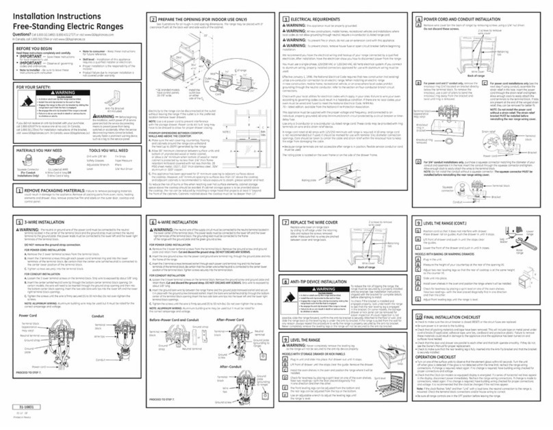
Roger Technology B70/1DCHP User manual

Quick Start B70/1DCHP
Rev02 03/04/2020
ROGER TECHNOLOGY
Via S. Botticelli 8 • 31021 Bonisiolo di Mogliano Veneto (TV) • ITALIA
P.IVA 01612340263 • Tel. +39 041.5937023 • Fax. +39 041.5937024
info@rogertechnology.com • www.rogertechnology.com
APower supply H07RN-F 3x1,5 mm2 double insulated cable
1Photocell - Receiver 5x0,5 mm2double insulated cable (max. 20 m)
2Photocell - Transmitter 3x0,5 mm2double insulated cable (max. 20 m)
3Flashing lamp unit 2x1 mm2double insulated cable (max. 10 m)
4Antenna RG58 50 Ohm cable for external use (max. 10 m)
5Selector / Keypad 3x0,5 mm2cable (max. 20 m)
1. Typical installation
B70/1DCHP is the range of 36V DC digital controllers installed with the BG30 product series for sliding gate applications.
EN
1
A
1
5
2
2
3
4

2. Electrical connections
3. Display: functions and settings
PROG TEST
+
-
Back
Programming Check error alarms
PARAMETER PARAMETER
VALUE
Increase value
Decrease value
Next
PROG TEST
+
-
Accessories illustrated are indicative only
+SC
8910 11 12 13 14 15
16 17 18
19 20 21 22 23
24 25 26 27
COM
FT2
FT1
COS2
COS1
COM
ST
+LAM
COM
COM
ANT
COR
+24V
PED
PP
CH
AP
ORO
COM
LNA
LNB
ENC
MOTOR
POWER SUPPLY 230Vac
YXZ
F2
FC SB
P
R
OG
TE
S
T
+
-
M
F4ES-F4S
Series
R85/60
BG30
CS/STD
1 2 3 2345
+- +-
TX RX
L
N
12
F1
1
FIFTHY/24BATTERIES
+
COM
NO
-
SEC2 SEC1
BATTERY
BATTERY CHARGER
TRANSFORMER
M
-+
YXZ
2 x 12V 4,5Ah

4. Before starting ...
a) Select the automation system model installed with the parameter .
PROG TEST
+
-
PROG
TEST
+
-
PROG TEST
+
-
GATE OPENS TO LEFT
GATE OPENS TO RIGHT
BG30/1600 BG30/1400/R
BG30/2200 BG30/1800/HS
BG30/1000/HS BG30/1500/HS
d) Move the gate into the completely CLOSE position.
Check that, by pressing the TEST button, the display
always shows FC.
e) Press the TEST button. Possible alarms and safety device messages:
SEE ACQUISITION PROCEDURE
b) Select the position of the motor relative to the gate with the parameter
. The default setting for this parameter is with the motor installed on
the right hand side of the gate (seen from interior side).
c) Adjust the (mechanical or magnetic) limitswitches
so that, once triggered, the gate stops slightly
before it reaches the mechanical stop.
CLOSING LIMIT SWITCH OPENING LIMIT SWITCH
00 No safety device in alarm state and no limit switch activated.
Sb (Sb) Release handle or lock open.
STOP contact (N.C.) open.
Jumper the STOP contact.
5 Sensing edge contact COS1 (N.C.) is open. Check connection. If sensing
edge is not installed, disable with 3 00.
4 Sensing edge contact COS2 (N.C.) is open. Check connection. If sensing
edge is not installed, disable with 4 00.
3 Photocell contact FT1 (N.C.) is open. Check connection. If photocell is not
installed, disable with 50 00.
2 Photocell contact FT2 (N.C.) is open. Check connection. If photocell is not
installed, disable with 53 00.
fe Both limit switches in error state. Check connections and settings of limit
switches.
fa If gate is open, gate open limit switch is detected.
fC If gate is closed, gate closed limit switch is detected.

Speed Speed
Closing speed BH30/HS-BM30/HS
Approach
distance
Approach
speed
Approach distance
Approach speed
Deceleration
Deceleration
during closure BH30/HS-BM30/HS
Deceleration
Acceleration Acceleration
Acceleration during closure
BH30/HS-BM30/HS
CLOSE OPEN
Boost during aperture
Boost during closure
0° 0°
Maximum motor torque setting according to defined time
Setting motor torque
Minimum torque
Maximum torque
Obstacle detection
sensitivity setting
Maximum sensitivity
Minimum sensitivity
Setting reverse time after
activation of sensing edge
or obstacle detection
(crush prevention).
5. Acquisition procedure
1. Press and hold PROG for 4 seconds.
2. APP- appears on the display.
3. Open the release cover.
4. PHAS appears on the display.
5. Wait until the message PHAS flashes.
6. Close the release cover.
7. If the photocells are connected and enabled (FT1/FT2), the message FOTO flashes. NOTE: do not break the photocell barrier beam.
8. AUTO appears on the display.
9. The gate starts to open.
10. Once the gate is open, the message AUTO flashes on the display after a few seconds and the gate starts to close.
11. When the gate is closed, the safety device symbols are displayed.
PROG
AP P- PH A5 AU to
x4 s
x5 s
OPENING OPEN CLOSING
(if FT1/FT2 are
connected or enabled)
CLOSE
Yes
AU
AU
to
to
PH
PH
A5
A5
FO
FO
TO
TO
CLOSE
6. Setting basic parameters

7. Programming a NEW transmitter
8. Copying a transmitter
1. Press channel P1 (P2) of the receiver.
2. When LED L1 (L2) ashes 3 times (or 4 times
with rolling code function), press any button
on the transmitter.
3. If LED L1 (L2) remains steadily lit the
transmitter has been stored correctly.
1. Press buttons A and B on the NEW
transmitter simultaneously.
2. The LED ashes for 5 s.
3. Hold button (A) only on the NEW transmitter
you want to store.
4. The LED ashes 3 s.
5. Hold the previously stored transmitter as
close as possible to the NEW transmitter.
6. Press button (A) on the OLD transmitter.
7. The LED lights for 1 s to conrm that the copy
procedure was successful.
P1
L1 L2
P2 P1
L1 L2
P2
ON
P1
L1 L2
P2
1 click
x5 s x3 s x1 s
AAA
A
B
OLD
This document is a basic quick guide for the initial installation of a BRUSHLESS sliding gate motor.
For complete information concerning the control unit, the motor and the accessories mentioned in this quick guide, see the technical manuals available in the B2B area of the
website www.rogertechnology.it
9. Photocells grounding connection
Grounding connection negative terminal (COM) photocells series F4ES/F4S or other than Roger Technology
In case of malfunction, or failure to intervene in case of dimming, or continuous detection, or abnormal behaviour of the automation (gate, overhead door,
barrier, etc.), it is advisable to connect the negative terminal (COM) of the photocells to the grounding of the system.
+SC
8910 11 12 13 14 15
16 17 18
19 20 21 22 23 24 25 26 27 28 29
COM
FT2
FT1
COS2
COS1
COM
ST
+LAM
COM
ANT
+24V
PED
PP
CH
AP
ORO
COM
LNA
LNB
RX
TX
12 3 12
RX
TX
FT1
FT2
MASTER
SLAVE 1
345
123 12345
rosso
red
nero
black
F3
LN
COM(-)
COM(-)
COM(-)
COM(-)
COM(-)
COM(-)
Other manuals for B70/1DCHP
3
Table of contents
Popular Range manuals by other brands
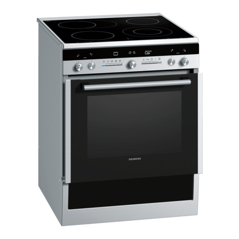
Siemens
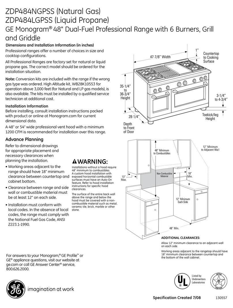
Siemens HC854 83 Series instruction manual

GE
GE JCB800 Owner's manual and installation instructions

GE
GE JGBP28BELWH Dimensions and installation information
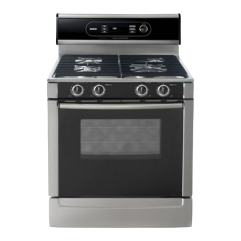
Bosch
Bosch HGS5022UC-01 use and care manual

Fisher & Paykel
Fisher & Paykel OR30SDG6X1 installation guide
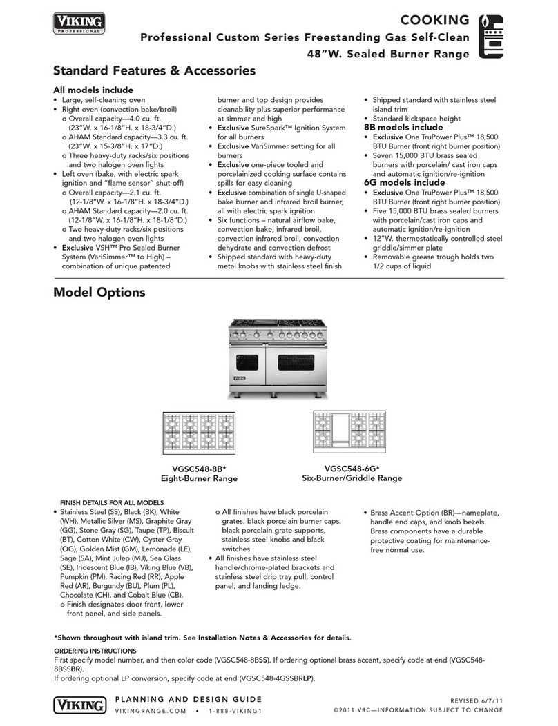
Viking
Viking VGSC548 Planning and design guide

