Rokon Motorcycle User manual

Illustrated
Owners and Parts Manual
ROKON International Inc.
50 Railroad Avenue
Rochester, NH 03839
Tel: 603 335-3200
Fax: 603 335-4400
e-mail:parts@rokon.com
web site: www.rokon.com
Made In
The USA
©2005 Rokon International, Inc. Printed in U.S.A. ROKON®and its logo are registered trademarks. Rev. 3

Welcome to the growing group of ROKON owners. All operators must read and familiarize
themselves with this owners manual and the safety information.
The ROKON Warranty Statement is enclosed with this manual. For it to be validated, the
complete ROKON Utility Vehicle Registration Card must be signed and returned to
ROKON within 10 days of the date of purchase.
We congratulate you on your decision to purchase a ROKON Utility Vehicle. By following
the procedures and suggestions outlined in this manual, you will be rewarded with many
hours of reliable, gratifying performance that others have come to expect from ROKON
Utility Vehicles.
ROKON INTERNATIONAL, 50 Railroad Ave., Rochester, New Hampshire 03839, U.S.A. Copyright 2004

TABLE OF CONTENTS
SECTION: Page
1. Safety Information 3-4
2. Description and Machine Identification 5
3. Control Functions 6-7
4. Pre-Operation Checks 8
5. Operating Your Rokon 9-10
6. Periodic Maintenance and Adjustment 11-15
7. Repair Procedures 16-21
8. Torque and other specification charts 22
9. Limited Warranty 23
10. Illustrated Parts Manual 24-53
BEFORE YOU OPERATE YOUR NEW ROKON, THE
FOLLOWING IMPORTANT POINTS MUST BE OBSERVED.
1. Children under 16 should not operate a ROKON.
2. Carefully read and follow the instructions in the safety section of this manual.
3. Carefully read and follow the setup procedure on the yellow card
attached to your ROKON (See yellow card instructions, also on page
56 of this manual).
4. Follow the Pre-Operation Checklist.
ROKON INTERNATIONAL, 50 Railroad Ave., Rochester, New Hampshire 03839, U.S.A. Copyright 2004

Always wear an approved motorcycle helmet that fits properly, eye protection (goggles
or face shield), gloves, sturdy boots, long sleeve shirt, jacket and pants while operating a
ROKON.
Never consume alcohol or drugs before or while operating a ROKON.
The ROKON is a go slow vehicle. Never operate at speeds too fast for your skills or the
conditions. Always operate at a speed that is appropriate for the terrain, visibility and
operating conditions and your experience.
DANGER-SERIOUS INJURY MAY RESULT! Never attempt wheelies, jumps or other
stunts of any kind while operating a ROKON.
Always keep both hands on the handlebars during operation.
Always go slow and be extra careful when operating on unfamiliar terrain. Always be
alert to changing terrain conditions when operating a ROKON.
Never operate on excessively rough, slippery or loose terrain until you have learned and
practiced the skills necessary to control the ROKON on such terrain.
Never operate on hills too steep for the ROKON or for your abilities. Never exceed a
60% grade (or 31 degrees). Practice on smaller hills before attempting larger hills.
Always follow proper procedures for climbing hills as described in this manual. Check
the terrain carefully before you start up any hill. Never climb hills with excessively slip-
pery or loose surfaces. Shift your weight forward when on an incline.
Always follow proper procedures for going down hills and for braking on hills as de-
scribed in this manual on pages 9 and 10. Check the terrain carefully before you start
down any hill. Shift your weight rearward. Never go down a hill at high speed. Shift into
1st range and keep the torque converter engaged for engine braking as described on
page 9 in this manual. Use the rear brake only in down hill corners. Apply the rear brake
before the front brake when going straight down.
Always maintain proper tire pressure.
Never modify your ROKON. Use only ROKON parts. Follow instructions, and properly
install ROKON parts.
Section 1 Safety Information
3
ROKON INTERNATIONAL, 50 Railroad Ave., Rochester, New Hampshire 03839, U.S.A. Copyright 2004

Never exceed the stated load capacity. Cargo should be properly distributed and se-
curely attached. Reduce speed and follow instructions in this manual for carrying cargo
or pulling a trailer. Be careful to allow greater distances for braking when carrying cargo
or operating with a trailer.
Read your engine manual completely and follow all safety instructions.
WARNING:
Potential Hazard- Improper Handling of Gasoline
can catch fire and you could be burned.
Always turn off the engine when refueling. Do not refuel right after the engine has been
running and is still very hot. Do not spill gasoline on the engine or exhaust pipe/muffler
when refueling. Never refuel while smoking, or while in the vicinity of sparks, open
flames or other sources of ignition such as the pilot lights of water heaters and clothes
dryers. When transporting the machine in another vehicle be sure that it is kept upright
and that the fuel cock is in the “OFF” position (see page 6 of manual). Otherwise, fuel
may leak out of the carburetor and flood the engine.
Gasoline is poisonous and can cause injuries. If you should swallow some gasoline
or inhale a lot of gasoline vapor, or get some gasoline in your eyes, see your doctor
immediately. If gasoline spills on your skin, wash with soap and water. If gasoline spills
on your clothes, change your clothes.
WARNING
Potential Hazard- Starting or running the engine
in a closed area.
Exhaust fumes are poisonous and may cause loss of consciousness and death within
a short time. Always operate your machine in an area with adequate ventilation
Section 1 Continued Safety Information
WARNING:
Potential bodily injury.
Never operate a ROKON without
the chain guards and side covers
in place and securely attached with
all fasteners properly tightened.
4ROKON INTERNATIONAL, 50 Railroad Ave., Rochester, New Hampshire 03839, U.S.A. Copyright 2004

Record the Vehicle Identification number and Engine Number in the spaces below to
facilitate ordering spare parts or for reference if the vehicle is stolen
VIN
Engine Number
Section 2 Description and
Machine identification
The Vehicle identification number
is on the center frame tube beneath
the driver seat.
The Engine number
is on the front of the
engine facing the
front wheel.
5
ROKON INTERNATIONAL, 50 Railroad Ave., Rochester, New Hampshire 03839, U.S.A. Copyright 2004

The Shut Off Switch is black in color and is located on the left hand side of
the handlebar. Pressing the “kill”switch will shut off the engine. This is a
safety feature and will allow the operator to immediately shut off the engine
in an emergency.
The Fuel Petcock located on the right hand side under the fuel tank shuts
off fuel flow to the engine. The down position is for fuel flow. The up position
shuts fuel off. Shut the fuel off when storing or transporting your ROKON.
Throttle. The engine is accelerated by twisting the throttle grip on the right
hand side of the handlebar counterclockwise. The throttle grip is spring
loaded and will automatically close the throttle and slow the engine when
released.
Brakes. The ROKON Utility Vehicle is equipped with separate front and rear disc brakes.
The left brake lever is for the
rear brake. The right brake lever is
for the front brake.
The Choke is used to start a cold engine and should be in the rearward
position to choke. It is located on the right hand side of the engine. As soon
as the engine starts, the choke should gradually be moved forward as
the engine warms up. It should be left fully forward for regular operation.
Section 3 Control Functions
6ROKON INTERNATIONAL, 50 Railroad Ave., Rochester, New Hampshire 03839, U.S.A. Copyright 2004

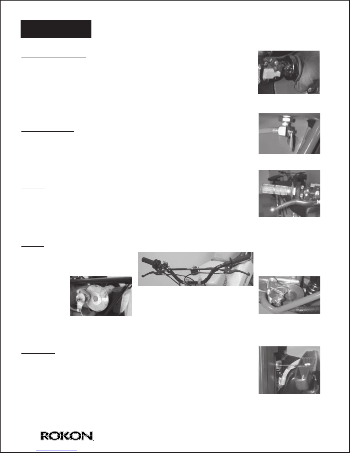
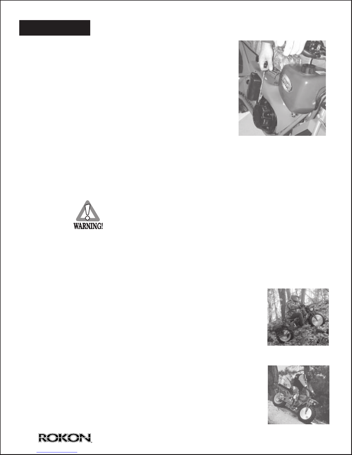
Recoil Starter. Firmly grasp the handle and pull slightly until engagement can
be felt. Then pull forcefully, being careful not to pull the rope all the way out.
Return the starter rope gently.
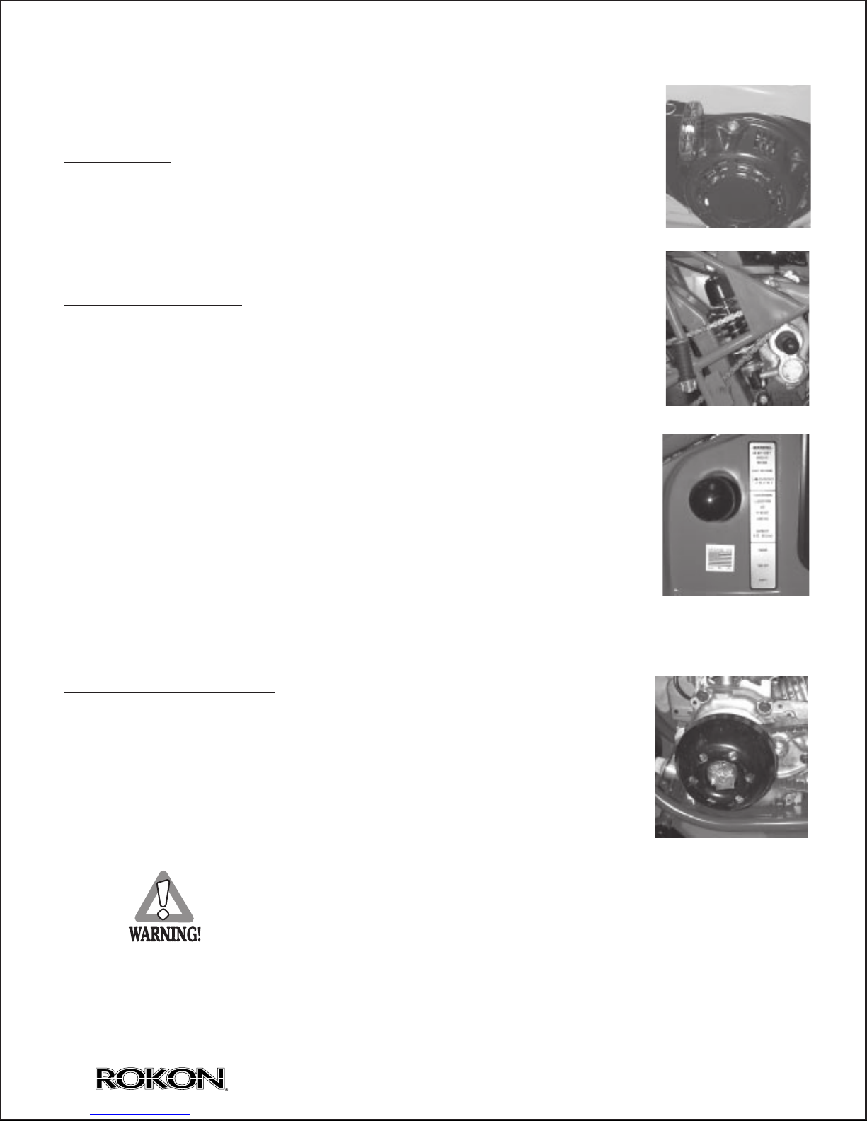
Rider Seat Suspension. The seat suspension spring can be adjusted to suit
the rider’s weight and riding conditions. Adjust the spring per load as follows:
To increase the spring preload, turn the adjuster clockwise. To decrease the
spring preload, turn the adjuster counterclockwise.
Transmission: The three range transmission is a ratio selector and when
coupled with the automatic torque converter, gives the vehicle extremely
broad capabilities, from steep climbing to normal transporting. The torque
converter provides a large overlap of speed and torque between gears.
This makes frequent gear changes unnecessary. Therefore, the trans-
mission has not been designed to shift in motion. STOP THE VEHICLE
BEFORE SHIFTING. Shift only at low idle or when the engine is off. Feel
the gears into engagement, rocking the bike, if necessary, to synchronize
the gears. The shift pattern is from inside out: 3-N-2-N-Low.
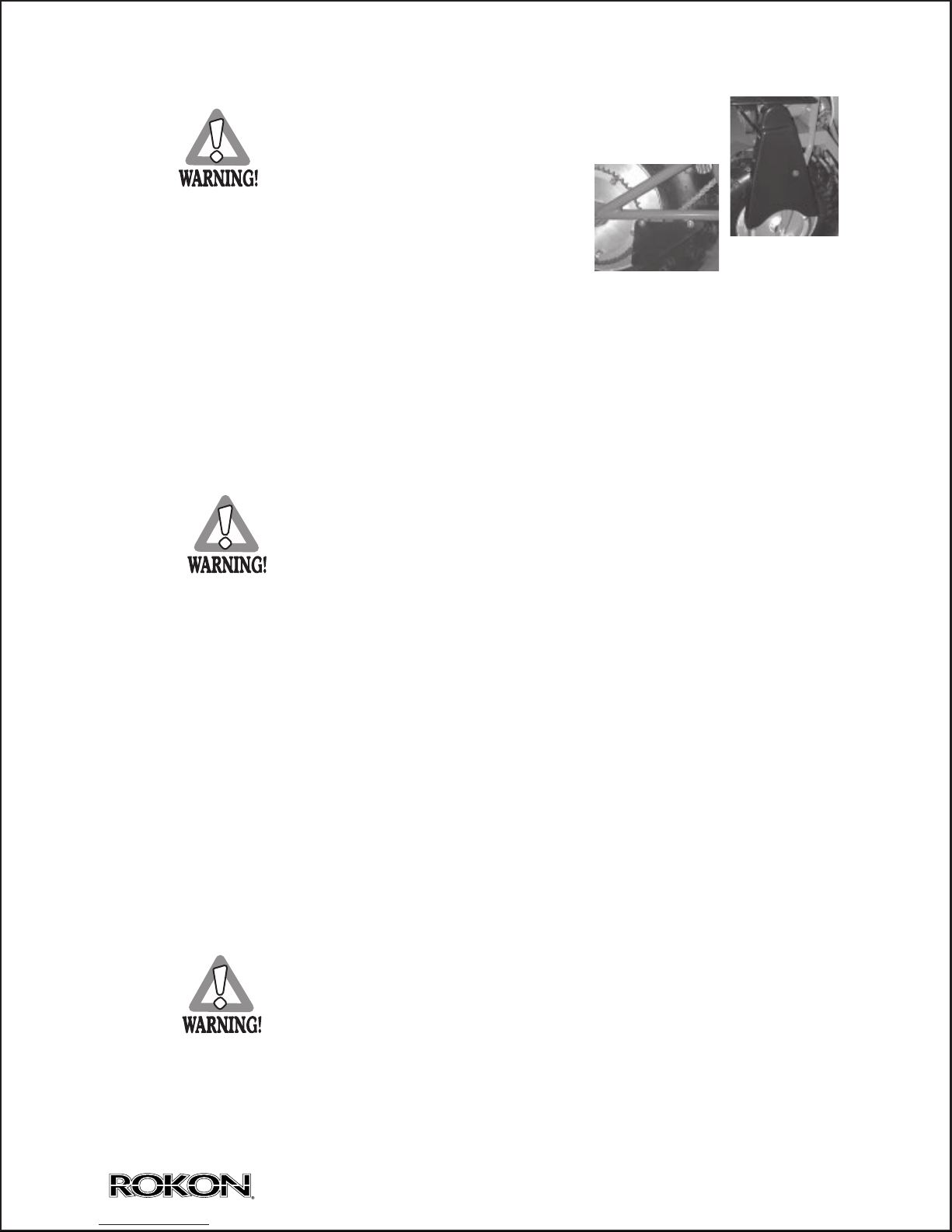
Automatic Torque Converter: The torque converter is designed especially
for ROKON and provides smooth automatic clutching and ratio
changing in response to throttle control and terrain requirements. The
front drive pulley tends to shift into high as engine speed is increased.
The rear driven pulley follows this speed change. If torque requirements
increase, the cam in the torque-sensing rear pulley overrides the front
pulley and forces a down shift without a loss of engine revs and power.
WARNING:
Potential Hazard- Starting the engine in gear.
could cause the Rokon to move forward unexpectedly.
PUT THE TRANSMISSION IN NEUTRAL BEFORE
STARTING THE ENGINE. Stand on the left hand side,
put the front Brake on with 2 fingers of your left hand, throttle
closed, reach over the ROKON and pull the starter handle.
Section 3 Continued Control Functions
7
ROKON INTERNATIONAL, 50 Railroad Ave., Rochester, New Hampshire 03839, U.S.A. Copyright 2004

Before using this machine, check the following points.
Front and Rear Brake. Check brake action. Check pucks to see that they are not over
worn. There should be visible brake material on both sides of the brake disc. See
Section 6.
Fuel Tank. Check fuel level. Fill as necessary. Use super unleaded for altitudes above
10,000 ft.
Engine Oil. The engine holds .6 qt. of SAE10W30/40 motor oil. Fill to the dipstick “full”
line.
Miter Box and Transmission. They are filled at the factory and need not be checked at
the start. The miter box should have 2.5 oz. of EP 80W90 gear lube oil. The transmis-
sion takes 6 oz. of EP 80W90 gear lube oil. The transmission has a fill to plug near the
bottom of the transmission( shown on page 46). There is no fill level for the miter box.
Over filling of either the miter box or transmission will result in leakage.
Throttle. Check for proper throttle cable operation. Look for smooth response to twist
action.
Wheels and Tires. Check Tire pressure, wear and damage.
Fittings and Fasteners. Check all fittings and fasteners.
Drive Chains. Check chains for tension and lubrication. Adjust tension for 1/2”- 3/4”
deflection at mid point.
Engine Manual. Read your engine manual completely and follow all instructions.
FAILURE TO INSPECT YOUR ROKON BEFORE OPERATION
INCREASES THE POSSIBILITY OF AN ACCIDENT OR EQUIPMENT
DAMAGE. ALWAYS INSPECT YOUR ROKON EACH TIME YOU USE IT
TO MAKE SURE IT IS IN SAFE OPERATING CONDITION.
Section 4 Pre-operation Checks
8ROKON INTERNATIONAL, 50 Railroad Ave., Rochester, New Hampshire 03839, U.S.A. Copyright 2004

When starting your ROKON, place the range selector in neutral.
Stand on left hand side, put the front brake on with two fingers of
your left hand, throttle closed, reach over the Rokon and pull the
starter handle. For a cold start put the choke on. Once the engine
turns over, set the choke off. Pull on the starter again and the
vehicle will start. Engage the three-range selector in the desired
gear range. Put the ball of the foot, rather than the instep on the footrest. Accelerate and
ride. Use braking as necessary. Pre-plan your route before attempting to negotiate
difficult terrain. Lean into the hill when climbing switch backs. Descend steep slopes at
slow speed in low range. Apply rear brake pressure before front brake application.
WARNING
Potential Hazard: Failure to use extra care when
operating a ROKON on unfamiliar terrain. Go slow
and be extra careful on unfamiliar terrain. You can
come upon hidden rocks, bumps, or holes, without
enough time to react. Always be alert to changing
terrain conditions when operating a ROKON.
Traversing a sloping surface requires you to properly position your weight
to maintain proper balance. As you travel across or up a slope, lean your
body in the uphill direction. It may be necessary to correct the steering when
riding on loose surfaces by pointing the front wheel slightly uphill. When
riding on slopes be sure not to make sharp turns either up or down hill,
which could cause a ROKON to turn over and cause the rider injury.
When riding downhill, shift your weight as far to the rear and uphill side
as possible. Use low gear and engage the throttle slightly to allow the
engine compression to provide braking. Whenever possible ride straight
downhill. Turn into corners with the rear brake only, so as not to slide the
front wheel and lose steering control.
Section 5 Operating Your ROKON
9
ROKON INTERNATIONAL, 50 Railroad Ave., Rochester, New Hampshire 03839, U.S.A. Copyright 2004

Section 5 Continued Operating Your ROKON
10
The ROKON can be used to cross slow moving shallow
water of up to a maximum of 24 inches in depth. Before
entering the water, choose your path carefully. Enter where
there is no sharp drop off, and avoid rocks or other obstacles
which may be slippery or upset the ROKON. Drive slowly
and carefully. Never change your
course in the middle of a stream or
you will find that slippery rocks and
currents might throw you out of balance.
If the water is over 24”in depth, always float your machine
across (hollow wheels only). Keep the air intake out of the
water to avoid flooding the engine compartment.
Riding over rough terrain should be done with caution. Look out for obstacles which
could cause damage to the ROKON or lead to an
upset or an accident. Avoid jumping the ROKON
as loss of control and damage may result.
The real secret to riding perfection is throttle control.
Remember that gradual acceleration will take you
anywhere you desire with the proper gear selection.
Your throttle is designed to retract upon release of
the hand as a safety measure for the rider. Always
grasp your throttle with ease, and never with full force.
The ROKON is designed with individual disc brakes on the front and rear gear boxes.
The right hand front brake will stop both wheels through the gear train. When braking
with the front brake, the machine should be in a “straight away”position. Hard braking,
with a turned front wheel, can cause a loss of steering which can result in loss of
control. The left hand rear brake should be used more often for going down steep
slopes.
ROKON INTERNATIONAL, 50 Railroad Ave., Rochester, New Hampshire 03839, U.S.A. Copyright 2004

Routine care of your ROKON vehicle is easily done and
is important for rider safety and vehicle longevity.
1. Inspect all fasteners for tightness.
2. The drive chains require adjustment at intervals, depending on the mileage and
the care which the operator has given the chains. Initial wear must be taken up
by adjustment after the first few hours of use. Total deflection should be 1/2”to 3/4”
when measured midway between the two sprockets of the most loose position.
To adjust the chains, loosen the axle bolts and the adjusting bolt lock nuts, and
turn the adjusting bolts equally in or out as required to give the chain the proper
setting. After adjusting the chain, rotate the wheel and check to make sure the
chain is aligned properly. Periodically, the chains should be removed from the
machine and cleaned in solvent and re-lubricated. They should be lubricated with
one of the chain lubricants on the market which can be applied to the chain in a
liquid form and will penetrate to the inner parts of the rollers.
3. Clean the air filter based on use. See Engine Manual.
4. Use normal repair procedures for tires and tubes. Re-seat the tire beads with 40
PSI , then deflate to the 3 -5 PSI operating pressure.
5. The Miter Box and Transmission should not require service other than checking
the oil level or replacing oil seals. The Miter Box should be removed and oil
changed yearly. The Miter Box is assembled with special tooling to determine the
correct tooth engagement and backlash. It is not advisable to attempt to dismantle
the unit, unless necessary. The transmission should be drained and refilled on the
same yearly schedule. There is a drain plug on the bottom of the transmission, a
fill level plug partway up, and a fill plug on the top. The Miter box takes 2.5 fluid oz.
of EP 80W90 gear lube oil. The transmission takes 6 fluid oz. of EP 80W90 gear
lube oil.
6. Check Belt for wear. Belts last at least a year and generally average 4-5 years.
7. Check the throttle for full return and feel.
Section 6 Periodic Maintenance
and Adjustment
11
ROKON INTERNATIONAL, 50 Railroad Ave., Rochester, New Hampshire 03839, U.S.A. Copyright 2004

Trouble Shooting
SYMPTOM PROBABLE CAUSE
1. Twist grip sticks.
Twist grip end rubbing on handlebar.
Deposit buildup under twist grip.
Worn or broken twist grip or throttle cable.
Throttle linkage improperly adjusted.
Moisture under grip freezing in cold temp.
2. Chains loosen frequently. Improperly seated chain adjustment bolts.
Loose axle bolts.
Improper chain alignment.
Chains need lubrication.
Twisted or distorted chains.
3. Excessive end play in wheel. Loose axle bolts.
Improper axle or wheel spacer thickness.
Defective wheel bearings.
Distorted bearing retainer housing in wheel.
4. Chain scoring tire sidewall. Improper chain alignment.
Improper axle spacer thickness.
Defective wheel bearings.
Section 6 Continued Periodic Maintenance and Adjustment
Storing your ROKON
1. Close the gasoline shut-off valve, this will prevent fuel leakage when
transporting or storing your ROKON. This is a key item when transporting
your ROKON for example on the wheel free carrier.
2. Start the engine and allow it to run until it stops from lack of fuel. This will use
up all the fuel in the carburetor and prevent the formation of deposits due to
evaporation of fuel.
3. Disconnect fuel line and permit all fuel to drain from the gasoline tank.
Replace the fuel line.
12 ROKON INTERNATIONAL, 50 Railroad Ave., Rochester, New Hampshire 03839, U.S.A. Copyright 2004

Trouble Shooting
SYMPTOM PROBABLE CAUSE
5. Noisy driveline.
Driveline improperly seated.
Worn or broken override spring.
Worn, broken or loose carrier bearing or bearing
retainer.
Worn bosses leading into override spring.
Worn universal joint.
6. Noisy front miter box.
Low oil level.
Loose gearbox mounting bolts.
Worn or broken bevel gears.
Worn shaft bearings.
Improper gear mesh.
7. Rear wheel won’t drive.
Wheel chain off sprocket.
Sheared roll pin on drive sprocket
8. Front wheel won’t drive.
Wheel chain off sprockets.
Sheared roll pin in sprocket.
Broken override spring on driveline.
Worn bosses leading to override spring.
Defective transmission.
9. Engine stalls when
Debris in carburetor.
machine stops.
Improperly adjusted throttle linkage.
Ice in system.
Idle set too low.
10.Valve core disappears
Tire pressure too low.
within wheel. (only tubed tires)
Tube not secured by stem kit.
Section 6 Continued Periodic Maintenance and Adjustment
13
ROKON INTERNATIONAL, 50 Railroad Ave., Rochester, New Hampshire 03839, U.S.A. Copyright 2004

Trouble Shooting Engine
SYMPTOM PROBABLE CAUSE
1. Engine will not start. No fuel in tank or shut-off valve closed.
Spark plug not firing.
Fuel not being delivered to combustion chamber.
Engine flooded. Too much fuel in combustion
chamber.
Improper spark plug gap.
Plugged fuel filter.
2. Engine hard to start. Water or dirt in fuel or stale fuel mixture.
Weak ignition spark.
Plugged air filter.
Engine over or under choked.
Gasket or seal leaks.
Spark plug fouled.
3. Engine starts but will Insufficient fuel supply.
not continue to run. Fuel line clogged.
Vent on filler cap plugged.
Dirty carburetor.
Air leak in fuel system.
Defective or fouled spark plug.
Idle screw not adjusted properly.
4. Engine misses. Dirt in fuel system.
Spark plug fouled or defective.
Faulty magneto or improper ignition coil air gap
setting.
Idle screw not adjusted properly.
5. Engine lacks power. Air cleaner clogged.
Incorrect spark plug –gap too wide or too narrow.
Incorrect air gap on ignition coil.
Worn or stuck piston rings or leaky head gasket.
Ice in system.
Hi altitude running. (use hi altitude jet)
Section 6 Continued Periodic Maintenance and Adjustment
14 ROKON INTERNATIONAL, 50 Railroad Ave., Rochester, New Hampshire 03839, U.S.A. Copyright 2004

Trouble Shooting Engine
SYMPTOM PROBABLE CAUSE
6. Engine overheats. Engine overloaded.
Oil too low in crankcase.
Incorrect spark plug.
Ignition timing over-advanced.
Scored piston or cylinder wall.
Lean Mixture.
Dirty air filter / blocked air intake.
7. Engine noisy or knocking. Loose flywheel.
Worn bearings.
Broken or loose parts inside engine.
Lack of oil in crankcase.
8. Engine stalls under load. Fuel line restricted or tank vent closed.
Engine overloaded.
9. Poor acceleration. Air cleaner clogged.
Ignition timing over-advanced or retarded.
Leaking gaskets.
Air gap too wide.
Exhaust restriction.
Low compression.
10.Poor high speed performance. Low compression.
Pre-ignition.
Spark plug or air gap improper.
Belt worn.
Brakes dragging.
Section 6 Continued Periodic Maintenance and Adjustment
15
ROKON INTERNATIONAL, 50 Railroad Ave., Rochester, New Hampshire 03839, U.S.A. Copyright 2004

Care and Adjustment of ROKON Brakes
General:
Rokon all wheel drive vehicles have individual front and rear disc brakes. They are cable operated
by hand levers on the handlebars. The left lever controls the rear brakes and, in the forward
direction, stops the rear wheel. The overrunning clutch in the driveline allows the front wheel to
continue rotating. The right lever operates the front brake and stops both wheels. The discs are
high mounted to keep them out of water and mud. Though small, they are powerful due to the
torque multiplication of the sprocket ratio.
Refer to the Rokon Parts Manual for help with part names and assembly sequence.
Maintenance:
The brakes operate with little or no maintenance, but work more smoothly and last longer if kept
clean and lubricated.
Be sure that all parts including the moveable pucks move freely and that the levers return fully.
Be sure that all fasteners are secure. Use self locking nuts, locktite or cotter pins on all fasteners.
Lubricate shaft and keys, push pins and cam, as needed, with a drop of motor oil.
Brake Pad
Brake Disc
Push Pins
Cam
Caliper
Key
Shaft
Cam Nut
Hitch Pin
or
Cotter Pin
Cable Clamp Screw
Cable Clamp Screw Cam
REAR
FRONT
Section 6 Continued Periodic Maintenance and Adjustment
16 ROKON INTERNATIONAL, 50 Railroad Ave., Rochester, New Hampshire 03839, U.S.A. Copyright 2004

Section 6 Continued Periodic Maintenance and Adjustment
Maintenance:
Cables are plastic lined and do not require lubrication though it is OK to do so.
Be aware that a drop of water in a cable may freeze and prevent braking. Use boots and
lubricants to prevent this. Test before riding off in freezing weather.
Replace pucks when they are down to 1/4 inch thick. The moveable puck is loose, but the
stationary puck is secured to the caliper with a small slotted head screw. Locktite this screw.
Adjustment:
New Pucks.
After installing new pucks, reassemble the calipers and securely tighten the two 5/16”screws.
Remove the cotter pin and finger tighten the cam nut so that the cam push pins are at the bottom
of the cam. This is the starting point. Now at the hand lever, set the cable housing adjusting
screw out about 1/4 inch and lock it up by finger tightening the lock nut. At the cam, loosen the
cable clamp screw and pull the cable through snugly and clamp it up. Now loosen the cam nut so
you can ride with a few fingers holding the brake lever, but with enough lever stroke left for locking
up the brakes if need be. Check for good braking and snappy return.
In The Field.
A quick adjustment for brake wear can be made without tools at the handlebar by loosening its
locknut and extending the cable housing adjusting screw. Retighten the locknut. It is best not to go
too far with his adjustment as the overextended adjustment screw may then get hit and broken.
When you can, return the cable housing adjusting screw to its normal 1/4 inch extension and take
up pad wear at the caliper by pulling the hitch or cotter pin, tightening the cam retaining nut and
replacing the pin.
Cable Housing
Cable Housing
Adjusting Screw
Lock Nut
Brake Lever
17
ROKON INTERNATIONAL, 50 Railroad Ave., Rochester, New Hampshire 03839, U.S.A. Copyright 2004

I.TRANSMISSION AND DRIVELINE REMOVAL PROCEDURE
Section 1, Procedure for transmission removal:
1. Elevate and secure the bike firmly to a non-moving stand. Bike should be elevated
so that the rear wheel is not touching the ground.
2. Remove all fiberglass side covers from the bike.
3. Shut fuel valve. Disconnect fuel line and plug, if necessary. Remove fuel tank.
4. Remove front seat. This is accomplished by removing the two attaching bolts on
each side of the front seat bracket and the bottom shock absorber attaching bolt.
The whole assembly can be removed and put aside.
5. If transmission and driveline need to be removed, the rear wheel and rear fender
will need to be taken off the bike. If only the transmission needs to be removed,
the rear wheel may stay intact.
See Section 2 for Drive Line Removal.
6. Remove the rear drive chain by locating the master link and separating it from the
chain.
7. Remove the rear driveline roll pin. (If transmission and driveline are to be taken
out as one unit, leave roll pin attached for ease of disassembly.) This is done by
inserting a pin punch into the roll pin access hole (located under the front seat,
which was removed), and driving the pin straight downward. Note: Rotate rear
wheel until hole lines up.
8. Remove drive belt.
9. Remove driven clutch. Loosen the three Allen screws behind the clutch. Note:
Driven clutch may be frozen on to the shaft. A small piece of wood and a mallet
from behind the clutch should ease removal. Care must be taken, not to damage
clutch. Use pry bars if necessary.
10. Remove muffler header pipe. (Loosen two 12mm nuts. Pull muffler off engine seat.
Pull muffler out of sleeve).
11. Remove rear brake caliper assembly. Take caution not to undo the brake line
from the spring assembly. Disconnect cotter pin and back off brake tension.
Remove brake caliper assembly and brake bracket as a complete unit. (Remove
the two 1/2 “bolts under the brake disc.). Slide Brake Disc off shaft. Take note
the way the caliper and brake disc came off for reassembly.
Section 7 Repair Procedures
18 ROKON INTERNATIONAL, 50 Railroad Ave., Rochester, New Hampshire 03839, U.S.A. Copyright 2004

12. Remove all four transmission attaching bolts, three on the frame mount, and one
next to the upper cross shaft. (Two should already be removed from the brake
bracket as described in step 11).
At this point: Transmission can be removed, by moving left to right to loosen
it from the Driveline clutch, sliding back into fender well, and carefully turning
sideways and pulling upward. Note: If the transmission can be shifted into 3rd
gear, it will ease removal, by having the shift ball closer to the transmission.
Reverse disassembly procedure for assembling.
Note: Replace worn parts as needed. (ie.: roll pins, Worn nuts or bolts, drive belt, etc.)
Use thread lock compound on transmission bolts upon reassembly.
Section 2, Procedure for Transmission and Driveline Removal:
1. Follow steps 1-5 in Section 1.
2. Remove in order: rear wheel, tail section of muffler, and rear fender.
3. Remove the two carrier bearing bolts, which are located under the fuel tank.
4. Remove front chain guard cover, front drive chain, and headlight. Note: Ground
wire for the headlight must be routed behind front miter box assembly.
5. Remove front brake caliper assembly. Note: Take caution not to undo the brake
line from the spring assembly. Disconnect cotter pin and relieve brake tension.
Remove two 1/2”bolts that secure the assembly to the bracket. Swing out of the
way. Remove brake disc.
6. Remove front miter box assembly. (This is done by removing the two 1/2”bolts
from behind the miter box assembly.) Pull miter box assembly straight out of
bore, with universal joint attached. Set aside.
7. Remove transmission assembly and drive line as one unit (Ease disassembly by
making sure the transmission is shifted into the highest gear. Shift ball closest to
the transmission.) Pull the assembly straight out of the bore.
8. Reverse procedure for reassembly.
Section 7 Continued Repair Procedures
19
ROKON INTERNATIONAL, 50 Railroad Ave., Rochester, New Hampshire 03839, U.S.A. Copyright 2004
This manual suits for next models
1
Table of contents
Other Rokon Motorcycle manuals