Roper Microwave Hood Combination User manual

Microwave Hood
Combination
Appliances
IMPORTANT:
Read and save
these instructions.
IMPORTANT
Installer: Leave Installation Instructions with the appliance.
Homeowner: Keep Installation Instructions for future reference.
Save Installation Instructions for local inspector’s use.
Part No. 4B75546A14358154

Beforeyoustart...
Remove all contents from the upper
cabinet.
Important: Observe all governing
codes and ordinances.
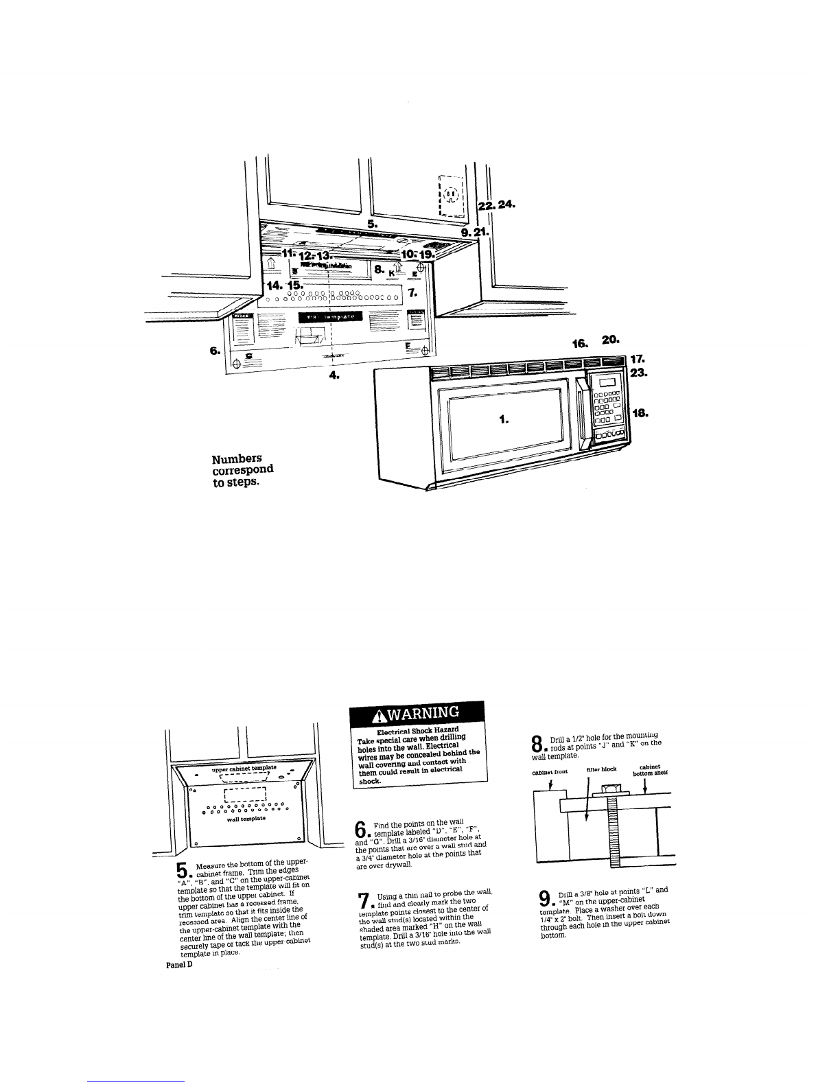
Check location where microwave oven
will be installed. The wall must be
strong enough to support the microwave
oven weight of 150lbs., plus the weight
of any items placed inside the
microwave or the upper cabinet. The
location should be away from strong
draft areas, such as windows, doors,
and strong heating vents. The
microwave oven should be located for
convenient use in the kitchen.
Proper installation is the installer’s
responsibility. A qualified technician
should install this microwave oven.
Make sure you have everything
necessary for correct installation.
It is the responsibility of the installer to
comply with the installation clearances
specified on the serial/rating plate.
The serial/rating plate is located
Excessive Microwave Energy
Exposure
. Do Not attempt to operate this
microwave oven with the door
open.
. Do Not tamper with or defeat
the safety interlocks.
. Do Not place objects between
the microwave oven front face
and the door.
. Do Not allow soil or cleaner
residue to accumulate on
sealing surface of microwave
oven door.
. Do Not operate microwave
oven if it is damaged.
. The microwave oven door
must close properly to provide
safe operation. Do Not use
microwave oven if door is bent;
hinges and latches are broken
or loose; or door seals, sealing
surfaces or glass are broken.
n
The microwave oven should
only be adjusted and repaired
by a qualified repair person.
. Have a qualified repair person
check for microwave leakage
if a repair is made.
Failure to use microwave oven
except as instructed may result
in exposure to excessive
microwave energy.
behind the micr&vave oven door on
the front frame of the microwave oven. Electrical ground is required. See
Electrical requirements.
III
For comer installations, allow
enough clearance to fully open
door so that rack and cooking
utensils can be removed
Y
I-
30” min cabinet
opening width
c I Y
t
15” minimum’microwave
oven to cooking surface
orcountertop
30” min~clearance from
. . .
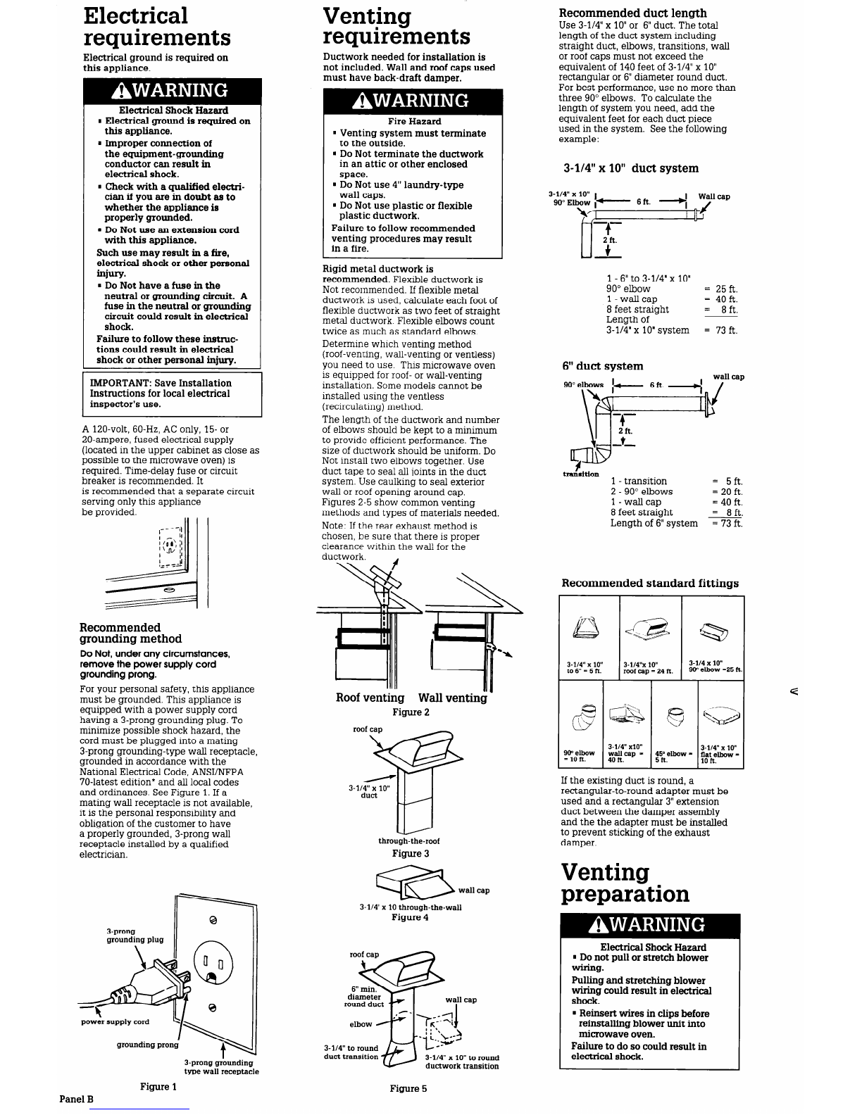
Wall construction should
be a minimum of 2”x 4”
wood studding and 3/8”
thickness drywall or
Use templates included
with installation
instructions.
Remove all packaging material from
inside microwave oven. Check the
microwave oven for damage - see
WARNING for excessive microwave
energy exposure. If any damage is
evident, do Not operate the microwave
oven until it is checked by an authorized
Whirlpool service technician
Personal Injury Hazard
Two people are required to lift
this microwave oven.
Failure to use more than one
person during installation may
result in personal injury.
. This microwave oven must be
mounted against and supported
by a flat, vertical wall.
. This microwave oven must be
attached with two lag screws
to a minimum of one, vertical
2” x 4” wall stud.
HDo Not mount microwave oven
to an island or peninsula cabinet.
wThe microwave oven top and
rear supporting structures must
be capable of supporting 150 lbs.,
plus the weight of any items
placed inside the microwave
oven or upper cabinet.
Failure to mount the microwave
oven as instructed could result in
personal injury and/or property
damage.
Electrical Shock Hazard
It is the customer’s responsibility:
. To contact a qualified
electrical installer.
. To assure that the electrical
installation is adequate and in
conformance with National
Electrical Code, ANSVNFPA 70-
latest edition*, and all local codes
and ordinances.
Failure to do so could result in fire,
electrical shock or other personal
injury.
Tools and
materials needed
Property Damage
Place a portion of carton or another
heavy material over the countertop
or cooktop before installing the
microwave oven. Do Not use a
plastic cover.
Failure to protect cooking surface
or countertop could result in
property damage.
I
NOTE:
Do Not use this microwave oven
for commercial purposes. This
microwave oven is designed for
household use only.
316” and 314”
wood drill bits
Parts supplied
for installation:
saber saw V 6-j
,. //A
m
4, l/4” x 3”
toggle bolts
69
4 spring
toggle-heads
2, l/4” x 2” bolts
mTake special care when drilling
holes into the wall. Electrical
wires may be concealed behind
the wall covering and contact
with them could result in
electrical shock.
mLocate any electrical circuits
that could be affected by the
installation of this product and
disconnect power circuit.
Failure to do so could result in
electrical shock.
screwdriver II -
gq
4,114” x 2” lag screws
&
1, power cord clamp and
1, mounting screw 2 tapping screws
(dark-colored) (bright-colored)
measuring rape
carton or another heavy material
1 power cord
bushing
l
Copies of the standard listed
may be obtained from:
National Fire Protection Association
Batterymarch Park
Quincy, Massachusetts 02269
for covering countertop
Special hardware and tools are required
for brick or masonry walls. At least four
anchor bolts must be anchored into the
wall and the mounting area must be
capable of meeting the 150lb.-weight
requirement.
2 filter screens
Panel A

Electrical Venting
requirements requirements
Electrical ground is required on
this appliance.
Electrical Shock Hazard
wElectrical ground is required on
this appliance.
n
Improper connection of
the equipment-grounding
conductor can result in
electrical shock.
n
Check with a qualified elect&
cian if you are in doubt as to
whether the appliance is
properly grounded.
n
Do Not use au extension cord
with this appliance.
Such use may result in a fire,
electrical shock or other personal
iujury.
n
Do Not have a fuse in the
neutral or grounding circuit. A
fuse in the neutral or grounding
circuit could result in electrical
shock.
Failure to follow these instruc-
tions could result in electricaI
shock or other personal injury.
Instructions for local electrical
A 120-volt, 60-Hz, AC only, 15- or
20-ampere, fused electrical supply
(located in the upper cabinet as close as
possible to the microwave oven) is
required. Time-delay fuse or circuit
breaker is recommended. It
is recommended that a separate circuit
serving only this appliance
be orovided.
Recommended
grounding method
Do Not, under any circumstances,
remove the power supply cord
grounding prong.
For your personal safety, this appliance
must be grounded. This appliance is
equipped with a power supply cord
having a 3-prong grounding plug. To
minimize possible shock hazard, the
cord must be plugged into a mating
3-prong grounding-type wall receptacle,
grounded in accordance with the
National Electrical Code, ANWNFPA
70-latest edition* and all local codes
and ordinances. SeeFigure 1.If a
mating wall receptacle is not available,
it is the personal responsibility and
obligation of the customer to have
a properly grounded, 3-prong wall
receptacle installed by a qualified
electrician.
3-prong
grounding plug
power supply cord
Panel B
3-prong grounding
type wall receptacle
Figure 1
Ductwork needed for installation is
not included. Wall and roof caps used
must have back-draft damper.
Fire Hazard
. Venting system must terminate
to the outside.
n
Do Not terminate the ductwork
in an attic or other enclosed
space.
. Do Not use 4” laundry-type
wall caps.
n
Do Not use plastic or flexible
plastic ductwork.
Failure to follow recommended
venting procedures may result
in a fire.
Rigid metal ductwork is
recommended. Flexible ductwork is
Not recommended. If flexible metal
ductwork is used, calculate each foot of
flexible ductwork as two feet of straight
metal ductwork. Flexible elbows count
twice as much as standard elbows.
Determine which venting method
(roof-venting, wall-venting or ventless)
you need to use. This microwave oven
is equipped for roof- or wall-venting
installation. Somemodels cannot be
installed using the ventless
(recirculating) method.
The length of the ductwork and number
of elbows should be kept to a minimum
to provide efficient performance. The
size of ductwork should be uniform. Do
Not install two elbows together. Use
duct tape to seal all joints in the duct
system. Use caulking to seal exterior
wall or roof opening around cap.
Figures 2-5 show common venting
methods and types of materials needed.
Note: If the rear exhaust method is
chosen, be sure that there is proper
clearance within the wall for the
ductwork.
Roof venting
--.
Wall venting
Figure 2
roof cap -
w
3-l/4” x lo”
duct
-l-ll
through-the-roof
Figure 3
a wallcap
3-l/4’ x 10 through-the-wall
Figure 4
3-114” to round
duct transition 3-l/4” x 10” to round
ductwork transition
wall
7,--q
I
Recommended duct length
Use 3-l/4” x 10”or 6” duct. The total
length of the duct system including
straight duct, elbows, transitions, wall
or roof caps must not exceed the
equivalent of 140 feet of 3-l/4” x 10”
rectangular or 6” diameter round duct.
For best performance, use no more than
three 90” elbows. To calculate the
length of system you need, add the
equivalent feet for each duct piece
used in the system. Seethe following
example:
3-l/4” x 10” duct system
3-l/4” x lo” 1
SO”Elbow ,- 6ft.
\q -.-
II 4
u
2-f%..
+
1 - 6”to 3-l/4’ x 10”
90” elbow = 25 ft.
1 - wall cap = 40 ft.
8 feet straight = 8ft.
Length of
3-114”x 10”system = 73ft.
6” duct system
wall caP
6ft. ,,I
tralhtion 1 - transition = 5ft.
2 - 90” elbows = 20 ft.
1 - wall cap = 40 ft.
8 feet straight = 8ft.
Length of 6” system = 73 ft.
Recommended standard fittings
7
kc3
-
3.114” x lo”
to 6” = 5 ft.
a
a
i’
90” elbow
= 10 ft.
3.1/4”x 10” I
3-114 x lo”
roof
cap =
24 ft. 90” elbow -25 h
3-114” x10”
wallcap -
40 ft.
3-114” x lo”
flat elbow -
10 ft.
If the existing duct is round, a
rectangular-to-round adapter must be
used and a rectangular 3” extension
duct between the damper assembly
and the the adapter must be installed
to prevent sticking of the exhaust
damper.
Venting
preparation
Electrical Shock Hazard
mDo not pull or stretch blower
wiring.
Pulling and stretching blower
wiring could result in electrical
shock.
. Reinsert wires in clips before
reinstalling blower unit into
microwave oven.
Failure to do so could result in
electrical shock.
Figure 5

This microwave oven is shipped with
the blower assembled for ventless
(recirculating) installation. Adjustments
must be made for roof-and wall-venting
installation. Follow these instructions for
preparing your microwave oven for the
type of venting method you need.
Now start...
with microwave oven in kitchen.
1
Remove shipping materials and
. parts from inside microwave oven.
For all installations:
Floor Damage
Slide range onto cardboard or
hardboard before moving across floor.
Failure to do so may damage floor
covering.
e. Reattach the blower plate to
microwave oven with the six,
blower-plate screws.
2
Disconnect and move a
. freestanding range out of the
cabinet opening to provide easier
access to the upper cabinet and back
wall. Put a thick, protective covering
over a cooktop, set-in range or
countertop to protect from damage
and dirt.
a. Remove the three screws from the
grille on the top front of the microwave
oven. Remove the grille. Set grille and
screws aside.
-
-
rod retainer -
-
screw
3
d
on top of tab for
proper venting
f. Align the damper/duct connector
with the vent on top of the microwave
oven. Damper should be on top of tab.
Use two tapping screws (bright-colored)
to attach damper/duct connector to the
microwave oven.
b. Loosen rod retainer screws and
remove wall mounting plate from the
rear of the microwave oven.
Wall-vented installation:
u
Roof-vented installation:
0
a. Remove and save the six, blower-
plate screws and blower plate.
b. Carefully pull the blower unit out of
the microwave oven, slipping wires out
of clips.
a. Remove and save the six, blower-
plate screws and blower plate.
b. Carefully
pull
the blower unit out of
the microwave oven.
3
Using a plumb line and measuring
n
tape, determine and clearly mark a
vertical center line on the wall in the
area the microwave oven is to be
installed. Find and mark the location
of the wall stud(s) on the wall; then
measure and mark their location on the
wall template. If one wall stud cannot
be found in the
area
where the
microwave oven is to be installed,
consult a local building contiactor. Do
Not attempt to install microwave oven if
a wall stud cannot be found.
c. Rotateblower /h%Lda+-\
4
Center wall template in opening
n
by lining up the plumb line on
wall with center line on wall template.
Make sure the minimum width is 30
inches and that the top of the wall
template is located a minimum of 30
inches above the cooking surface.
Securely tape or tack the wall template
to the wall.
Note :
. If cabinets are not plumb, adjust the
wall template to the cabinets.
. If front edge of cabinet is lower than
the back edge, adjust the wall
template so that it is level with the
cabinet front.
unit end over
end.
Rotatethe
unit 180”so that
the exhaust
c. Rotateblower unit l/4 turn so that
the exhaust ports face the top of the
unit.
ports
face the
rear of the unit. \
Slip wires into clips
at the upper left hand
comer bi blower unit.
d. Place blower unit back into
microwave oven.
d. Place blower unit back into
microwave oven.
e. Reattach the blower plate to
microwave oven with the six, blower-
plate screws.
Panel C

II
22.24.
44.
-15. ;
000
0000
30
000
000
0000;
‘8
00000000f00
Numbers
correspond
to steps.
electrical Shock Hazard
Take special care when drilling
holes into the wall. Electrical
wires may be concealed behind the
wall covering and contact with
them could result in
eleCtriCal
shock.
8
Drill a l/Z” hole for the
mOUnttig
s rods at points “J” and “K” on the
wall template.
cabinet front filler block cabinet
bottom shelf
.
6
Find the points on the wti
mtemplate labeled “D”, “El’, ‘IF”,
and “G”. Drill a 3116”diameter hole at
the points that are over a
wall
stud and
a 3/4” diameter hole at the points that
are over drywall.
5
Measure the bottom of the upper-
. cabinet frame. Trim the edges
” A”
“$3” and “C” on the upper-cabinet
tem&e’so that the template will fit
On
the bottom of the upper cabinet. If
upper cabinet has a recessed frame,
trim template so that it fits inside the
recessed area. Align the center line of
the upper-cabinet template
With
the
center line of the wall template; then
securely tape or tack the upper-cabinet
template in place.
Panel D
9
Drill a 3/V hole at points “L” and
m“M” on the upper-cabinet
template. Place a washer over each
114”x 2” bolt, Then insert a bolt down
through each hole in the Upper cabinet
bottom.
using a thin nail to probe the
wall,
, find and clearly mark the
two
template points closest to the center of
the wall stud(s) located within the
shaded area marked “H” on the Wah
template. Drill a
3/16”
hole into the
Wd
stud(s) at the two stud marks.

If bottom of upper cabinet is
recessed 3/4” or more, align 2”x 2”
filler blocks of required thickness (not
included) with the shaded squares
marked “N” and “P” on the upper-
cabinet template. Mark the cut-out
position on the filler blocks through the
upper-cabinet holes “L” and “M”. Drill
3/8” diameter hole at the marks on filler
blocks. Attach filler blocks to upper
cabinet with the two l/4” x 2”bolts
and washers.
Electrical Shock Hazard
Install power-supply cord
bushing around hole drilled in a
metal cabinet. Failure to do so
could result in electrical shock.
10
Cut or drill a 2” diameter
, hole at the area marked
“power-supply-cord hole” on the upper-
cabinet template. If upper cabinet is
metal, install power-supply-cord
bushing around the edge of the hole
to prevent damage to the cord from the
rough metal edge.
11
Determine which venting
. method (roof-venting, wall-
venting, or ventless) you need to use.
This microwave oven is manufactured
for roof- or wall-venting installation.
12
To vent through the roof, cut
. out the rectangular area
marked “R” on the upper cabinet
template.
To vent through the wall, cut out the
rectangular area marked “S” on the
wall template.
Remove the upper-cabinet and wall
templates.
13
Install ductwork through the
. vent opening in the upper-
cabinet or wall. Complete the venting
system through the wall or roof
according to the method needed. See
Venting requirements and Venting
preparation. Use caulking to seal
exterior-wall or roof opening around
exhaust cap.
mountingplate
spring
toggle bolt
14
Insert lag screws through
n
the holes on the mounting
plate (“H”) where the mounting plate
will be attached to a wall stud. Insert
toggle bolts at “D”, “E”, “F”, and “G”,
where it will be attached to dry wall.
mounting
plate ”
Attach a spring toggle head to the end
of each toggle bolt. Leave at least one
wall-thickness of space between the
mounting plate and the end of the
spring toggle head so that the spring
toggle head can properly open on the
other side of the wall.
y/A damper must
*
--- be on top of
tab for proper
venting
15
If wall-vented installation
n
is used, attach damper to rear
of mounting plate. Align 3-l/4” x 10”
duct with damper and see that damper
moves freely.
Position the mounting plate on the wall
making sure that the top of the
mounting plate is 3/16” below the
bottom of the cabinet frame. Insert the
toggle bolts and spring toggle heads
through the dry-wall holes and start the
lag screws through the wall-stud holes.
Tighten bolts and screws to secure
mounting plate to wall.
rear
mounting
plate
16
Insert a flat-blade screwdriver
n
through turn-rod clearance
holes in mounting plate and into
retainers. Move screwdriver around to
make sure the retainers move freely. If
retainers do not move freely, loosen
toggle bolts and lag screws, and
readjust mounting plate.
Personal Injury Hazard
Two people are required to lift
this microwave.
Failure to use more than one
person during installation may
result in personal injury.
17
Carefully lift the microwave
n
oven and hang it on the tabs
at the bottom of the mounting plate.
Reaching through upper cabinet, thread
power cord through the power-cord hole
in the bottom of the upper cabinet.
19
Using a flat-blade screwdriver,
. push in and thread the tum-
rod screws clockwise until they are
tight in rear, mounting-plate nuts.
Check that the microwave is securely
fastened to the mounting plate.
Personal Injury or Property
Damage Hazard
Secure the microwave oven with
the two mounting bolts inserted
through the upper cabinet holes.
Failure to do so could result in
personal injury and/or property
damage.
20
Tighten the bolts inserted in
. the upper cabinet holes until
the gap between the upper cabinet and
microwave oven is closed.
I
21
Mount the power-supply
w cord retainers as shown to
the inside of the cabinet. Use power-
supply-cord tie wraps to bundle the
power-supply cord and secure it to the
power-supply-cord retainers.
22
Reattach grille to the front of
n
the microwave oven with the
three grille screws.
23
Grasp filter screen Aith one
. hand holding the tab and the
other hand holding the opposite end.
Insert the end of the filter screen without
the tab into the opening and slide filter
screen toward the front of the
microwave oven.
18
Swing the microwave
n
oven upward so that the
top of the oven meets the top of the
mounting plate. Hold oven securely
Panel E

/ \’
\\ ! //
Insert the tab end of filter screen into the
opening and slide entire screen toward
the back of the microwave oven until
screen is securely in position.
Repeat for other filter screen.
24
Plug in the power supply
n
cord.
25
Read your Use & Care Guide,
n
then check the operation of your
microwave oven.
Congratulationsl
You have just ftished
installing your new,
Roper Microwave Hood
Combination. Keep
Installation Illstluctions
and Useand Care Guide
availdde for easy reference.
Part No. 4B75546AI4358 154
0 1991Roper Brand
If microwave
oven does not
operate...
Check that the circuit breaker is
not tripped or the fuse blown.
Check that the power-supply cord is
plugged into the wall receptacle.
Appliances
Benton Harbor, Michigan 49022
Accessory Kits
Accessory Kit No. 4158264 - Brown
4158439 - White
4158311 -Black
Filler panel kits are available from your
parts dealer to use when installing this
microwave oven in a 32”-or 42”-wide
opening. The filler panels come in pairs
and each panel is 3” wide.
Filler panels
Accessory Kit No. 4158440
A smoke deflector kit for some models
is available from your parts dealer to
use when installing this microwave
oven over cooking products with grill or
g-riddle.
Seeyour dealer for details.
Printed in Korea
This manual suits for next models
2
Table of contents
Other Roper Microwave Oven manuals

Roper
Roper lREB/Q User manual

Roper
Roper MW557 User manual

Roper
Roper M-ME 08XW User manual

Roper
Roper MHE14RF User manual

Roper
Roper MFE14XW0 User manual

Roper
Roper MCE04XW User manual

Roper
Roper MHE13 User manual

Roper
Roper MHEI IRD User manual

Roper
Roper MFE14XW User manual

Roper
Roper MCE04XW1 User manual