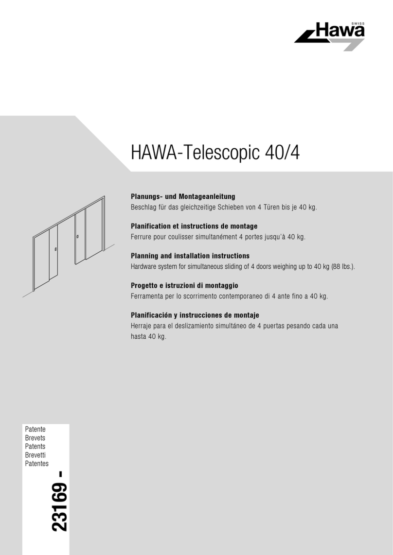
Roto NT Series User manual

Window and Door Technology
Roto NT
The world’s biggest selling
Tilt&Turn hardware system for windows and balcony doors
Installation, maintenance and operation instructions
for timber and PVC balcony doors with thresholds

Imprint
Copyright: July 2014
Roto Frank AG
Window and Door Technology
Wilhelm-Frank-Platz 1
70771 Leinfelden-Echterdingen
Germany
Phone +4971175980
Fax +497117598253
info@roto-frank.com
www.roto-frank.com

Subject to change. Roto NT IMO_347_EN_v0
.July 2014
.3
General information Information on these instructions....................................................6
Responsibility of the target groups .................................................. 8
Instruction obligation of the target groups ......................................9
Explanation of the safety instruction symbols ...............................10
Limitation of liability......................................................................11
Security Stipulated use................................................................................ 12
Stipulated application for end-users .............................................. 13
Safety instructions......................................................................... 14
Safety information for end-users .................................................. 15
Fabrication advice for timber and PVC........................................... 16
Screw fixing .................................................................................. 17
Timber........................................................................................................ 17
PVC............................................................................................................ 18
Information on the product
Eifel TB threshold ..........................................................................20
Dimensional data for hardware...................................................... 21
Cross section of sash profile with Eifel TB threshold ................................. 21
General hardware characteristics .................................................. 22
NT hinge side K.......................................................................................... 22
NT hinge side E5........................................................................................ 23
NT Power Hinge......................................................................................... 24
NT Designo ................................................................................................ 25
Application diagram....................................................................... 26
NT hinge side K 3 / 100, K 6 / 100 (PVC) ...................................................... 26
NT hinge side E5 (timber) .......................................................................... 27
NT Power Hinge (timber) ........................................................................... 28
NT Designo (timber, PVC) .......................................................................... 29
Hardware overview Explanation on the hardware overview chapter ............................. 31
NT hinge side K (PVC) – Turn-Only and Tilt&Turn hardware........... 32
Basic security............................................................................................. 32
RC1/RC1N and RC2 (DIN EN 1627–1630) .............................................. 34
NT hinge side K (PVC) – Turn-Only / Tilt&Turn hardware ............... 36
Basic security............................................................................................. 36
RC1/RC1N (DINEN1627–1630) ............................................................. 38
NT hinge side E5 (timber) – Turn-Only and Tilt&Turn hardware .... 40
Basic security ............................................................................................ 40
RC1/RC1N and RC2 (DIN EN 1627–1630) .............................................. 42
General information
Contents

4
.July 2014
.IMO_347_EN_v0 Roto NT Subject to change.
General information
Contents
NT hinge side E5 (timber) – Turn-Only / Tilt&Turn hardware .......... 44
Basic security............................................................................................. 44
RC1/RC1N (DINEN1627–1630) ............................................................. 46
NT Power Hinge (timber) – Turn-Only and Tilt&Turn hardware ...... 48
Basic security ............................................................................................ 48
NT Designo (timber, PVC) – Turn-Only and Tilt&Turn hardware ..... 50
Basic security ............................................................................................ 50
RC1/RC1N and RC2 (DIN EN 1627–1630) .............................................. 52
NT Designo (timber, PVC) – Turn-Only / Tilt&Turn hardware .......... 54
Basic security............................................................................................. 54
RC1/RC1N and RC2 (DIN EN 1627–1630)............................................... 56
Parts list – Roto Eifel TB
Eifel TB threshold ..........................................................................58
From Eifel 40 TB to Eifel 75 TB .................................................................. 58
From Eifel 80 TB to Eifel 140 TB ................................................................ 59
From Eifel 70 TB to Eifel 90 TB .................................................................. 60
Threshold brackets and setting post brackets............................................ 61
Accessories ................................................................................... 62
Additional profiles ...................................................................................... 62
Wind-stop .................................................................................................. 66
Aero-stop ................................................................................................... 67
Gaskets ...................................................................................................... 68
Juist construction connection sheeting ..................................................... 69
Installation
NT hinge side K ............................................................................. 70
Sash drillings for threshold application ...................................................... 70
Sash drillings for threshold application ...................................................... 71
NT hinge side E5............................................................................ 72
Sash drillings for threshold application ...................................................... 72
NT Power Hinge............................................................................. 73
Frame drillings and routings for threshold application............................... 73
NT Designo ................................................................................... 76
Carrying out frame and threshold drillings................................................. 76
Hinging the sash........................................................................................ 77
Roto Eifel TB.................................................................................. 80
Striker receiver........................................................................................... 80
Installation drawings Positioning of the frame components – All hinge sides.................. 82

Subject to change. Roto NT IMO_347_EN_v0
.July 2014
.5
Adjustment Explanation on the adjustment chapter.......................................... 86
Locking cam .................................................................................. 87
Operation Operating information.................................................................... 88
Operation information for end-users ..............................................89
Troubleshooting ............................................................................ 90
Maintenance Maintenance .................................................................................. 92
Lubrication points.......................................................................... 93
Inspection and care .......................................................................94
Preservation of the surface finish .................................................. 95
Dismantling Unhinging the sash........................................................................ 97
Sash stay 250, 350 and 500....................................................................... 97
Transport Transport, packaging, storage ....................................................... 98
Transport inspection ...................................................................... 99
Disposal Disposal of window hardware ..................................................... 101
General information
Contents

6
.July 2014
.IMO_347_EN_v0 Roto NT Subject to change.
This manual contains important information, instructions and application
diagrams (maximum sash sizes and sash weights) as well as installation
instructions regarding the further work of the hardware.
Also, this manual contains binding guidelines to ensure the duty to instruct
through to the end-user.
The information and instructions in this manual refer to the products of the
Roto NT hardware system.
Apart from these installation, maintenance and operation instructions, the
following documents apply:
Directives of the Quality Assurance Association: Locks and Hardware
(Richtlinie der Gütegemeinschaft Schlösser und Beschläge e.V.)
Directives VHBE of the Quality Assurance Association: Locks and Hardware
(Richtlinie VHBE der Gütegemeinschaft Schlösser und Beschläge e.V.)
This manual should be stored in such a manner that it can be quickly used,
if needed.
Additional markings
To highlight handling directives, results, lists, references and other elements,
the following signs are used in this manual:
Marking Explanation
Sash
Frame
Drill holes
1
Hardware components
1.
Action steps
First level of the hierarchy in a list
–Unordered list (second level of the hierarchy)
p. 12 (Cross) reference in tables
Refer to page12 (Cross) reference in the text
General information
Information on these instructions

Subject to change. Roto NT IMO_347_EN_v0
.July 2014
.7
General information
Information on these instructions
Marking Explanation
BA Hardware axis
BZ Supporting-pins
DIN L / R DIN left/right
T&T Tilt&Turn hardware
SRW Sash rebate width
SRH Sash rebate height
S.kg Sash weight
CON Connectable
CL Centre lock
LMD Lifting mishandling device
not dep. not depicted
RC1/RC1NResistance Class 1
RC2/RC2NResistance Class 2
SEC Security
All dimensions stated in mm. Other values are specified.
Protection of copyright
The contents of this manual are protected by copyright. In the framework
ofthe hardware manufacturing, the use of the contents is allowed. Any
other or further use is not permitted without written permission of the
manufacturer.

8
.July 2014
.IMO_347_EN_v0 Roto NT Subject to change.
The information in this document is aimed at the following target groups:
Hardware dealers
The “hardware dealers” target group includes all companies/persons who
purchase hardware from the hardware manufacturer to resell it without the
hardware being modified or subject to further work.
Manufacturers of windows and balcony doors
The “manufacturers of windows and balcony doors” target group includes
all companies/persons who purchase hardware from the hardware manu
-
facturer or the hardware dealer and build it into windows and balcony
doors.
Building element dealers/Installation company
The “building element dealers” target group includes all companies/persons
who purchase windows and balcony doors from the manufacturer of
windows
and balcony doors in order to sell these on and to install them
into a building development, without the windows or balcony doors being
modified.
The “installation company” target group includes all companies/persons
who
purchase windows and balcony doors from the manufacturer of
windows
and balcony doors,
or from a building element dealer, in order to
sell these and to install them into a building development,
without the
windows
or balcony doors being modified.
Builder
The “builder” target group includes all companies/persons who order
windows and/or balcony doors for installation into their building project.
End-users
The “end-users” target group includes all persons who operate the installed
windows and/or balcony doors.
General information
Responsibility of the target groups

Subject to change. Roto NT IMO_347_EN_v0
.July 2014
.9
General information
Instruction obligation of the target groups
NOTE!
Every target group must fully comply with its instruction obligation.
Unless defined otherwise in the following, the documents and
information
may be transmitted e.g. as printed documents,
CD-ROM, or via Internet access.
Responsibility of the hardware dealer
The hardware dealer must transmit the following documents to the manu-
facturer of windows and balcony doors:
– Catalogue
– Installation, maintenance and operation instructions
– Directive for fixing load-bearing Turn-Only and Tilt&Turn hardware
components
(TBDK)
– Guidelines/advice on the product and on liability (VHBH)
– Guidelines/advice for end-users (VHBE)
Responsibility of the manufacturer of windows and balcony doors
The manufacturer of windows and balcony doors must transmit the
following
documents to the building element dealer or to the builder, even
when a subcontractor (installation company) is acting as an intermediary:
– Installation, maintenance and operation instructions
– Directive for fixing load-bearing Turn-Only and Tilt&Turn hardware
components
(TBDK)
– Guidelines/advice on the product and on liability (VHBH)
– Guidelines/advice for end-users (VHBE)
The manufacturer must ensure that the end-user is provided with the
documents
and information intended for him, in printed format.
Responsibility of the building element dealer/installation company
The building element dealer must transmit the following documents to the
builder, even when a subcontractor (installation company) is acting as an
intermediary:
– Maintenance and operating instructions (with the focus on hardware)
– Guidelines/advice on the product and on liability (VHBH)
– Guidelines/advice for end-users (VHBE)
Responsibility of the builder
The builder must transmit the following documents to the end-user:
– Maintenance and operating instructions (with the focus on hardware)
– Guidelines/advice for end-users (VHBE)

10
.July 2014
.IMO_347_EN_v0 Roto NT Subject to change.
General information
Explanation of the safety instruction symbols
In this instructions, safety information is indicated by a symbol.
The safety
information is introduced by a key word that indicates the severity of the
danger.
DANGER!
This symbol in conjunction with the signal word indicates an
imminently
hazardous situation, which could result in death or
serious
damage to health if it is not avoided.
WARNING!
This symbol in conjunction with the signal word indicates a
potentially
dangerous situation, which could result in death or
serious
damage to health if it is not avoided.
CAUTION!
This symbol in conjunction with the signal word indicates a
potentially
dangerous situation, which may lead to minor or light
injuries if it is not avoided.
NOTE!
This symbol in conjunction with the signal word indicates a
potentially
dangerous situation, which may lead to property or
environ
mental damage if it is not avoided.

Subject to change. Roto NT IMO_347_EN_v0
.July 2014
.11
General information
Limitation of liability
All details and instructions in this document were compiled taking into
account
the relevant standards and regulations, the state of the art, and
also many years of knowledge and experience.
The hardware manufacturer accepts no liability for damages resulting from:
– Failure to comply with this document and all product-specific documents
and related applicable directives (refer to the chapters Security,
Stipulated use).
– Operation other than that stipulated use / misuse (refer to the chapters
Security, Stipulated use).
– Insufficient invitation to tender, failure to adhere to the installation
instructions
or application drawings.
– Increased soiling.
Claims by third parties against the hardware manufacturer on the ground
ofdamages resulting from misuse or failure to follow the instruction
obligation
on the part of the hardware dealer, the manufacturer of windows
and balcony doors, and of the building element dealer or the builder are
transferred accordingly.
The undertakings agreed in the delivery contract, the general conditions of
business and the delivery conditions of the hardware manufacturer, and
thelegal regulations applicable at the time of concluding a contract are
effective
.
The warranty covers only original Roto components.
The right to technical modifications for the improvement of performance
characteristics and for further development is reserved.

12
.July 2014
.IMO_347_EN_v0 Roto NT Subject to change.
Security
Stipulated use
Turn-Only and Tilt&Turn hardware is one-hand operation Turn-Only and
Tilt&Turn hardware for windows and balcony doors in building construction.
This is used to enable windows and balcony-door sashes into a turning
position
by operating a ‘hand-lever’ (handle) or into a limited tilting position
in the case of the scissors (sash-stay) version. Turn-Only and Tilt&Turn
hardware
is used on vertically installed windows and balcony-doors made of
timber, PVC, aluminium or steel and their corresponding material combina-
tions.
Turn-Only and Tilt&Turn hardware as covered by this definition,
locks
window and balcony door sashes or enables various ventilating positions.
When closing, the gasket counter force must be overcome as a rule.
Correct use also includes adhering to all the specifications in the product-
specific documents, such as:
– These
Installation, maintenance and operation instructions
– Product catalogues
– Information and specifications of the profile manufacturer (e.g. PVC or
light metal profiles etc.)
– The relevant directives TBDK and VHBE of the Quality Assurance Association:
Locks and Hardware (Gütegemeinschaft Schlösser und Beschlägee.V.)
– The valid national laws and directives
Any type of use that goes beyond or differs from the defined correct use
shall be regarded as misuse.
WARNING!
Danger from misuse!
Misuse and incorrect installation of hardware can result in
hazardous
situations.
– Never use hardware combinations that have not been approved
by the hardware manufacturer.
– Never use accessories that are not original products or that
have not been approved by the hardware manufacturer.

Subject to change. Roto NT IMO_347_EN_v0
.July 2014
.13
Security
Stipulated application for end-users
Turn-Only and Tilt&Turn hardware
For windows and balcony doors with Turn-Only and Tilt&Turn hardware,
window and balcony door sashes can be brought into a turn position or
into a limited tilting position by means of the scissor stay.
When a sash is closed and the hardware is locked, the resistance of a
gasket
usually needs to be overcome.
WARNING!
Danger of injury and material damage from incorrect closing
and opening the sash!
Incorrect closing and opening of sashes can result in serious
injuries
and significant material damage.
Therefore:
– Ensure that when closing the sash, it does not collide with the
frame or with another sash.
– Ensure that the sash is guided slowly by hand throughout the
entire range of movement as far as the fully closed position,
and that it is brought very slowly towards the frame.
– Ensure that the sash never slams closed or swings open in an
uncontrolled manner.
Any use beyond or other than the stipulated application and installation of
the products is deemed to be misuse and can result in dangerous circum
-
stances.
WARNING!
Danger from misuse!
Misuse of
windows
and
balcony doors
can result in dangerous
circum
stances.
In particular, avoid the following applications:
– insertion of obstacles in the opening area between the frame
and the window or balcony door sashes.
– the deliberate or negligent application of excessive loads on
windows and balcony doors.
– deliberate or uncontrolled slamming or pushing of windows
and balcony doors against the window reveal. This can destroy
the hardware, frame materials, or other individual components
of the windows or balcony doors.
Claims for damages of any type whatsoever resulting of operation other
than that stipulated are excluded.

14
.July 2014
.IMO_347_EN_v0 Roto NT Subject to change.
Security
Safety instructions
Turn-Only and Tilt&Turn hardware, Safety relevant symbols
Comply with the following symbols and their meanings in order to avoid
accidents
, injuries and material damage.
Symbol Meaning
DANGER!
Danger of injury from falling through open windows and
balcony doors.
– Behave with care near to open windows and balcony doors.
– Keep children and people who cannot estimate the dangers
away from the point of danger.
WARNING!
Danger of injury through trapping of body parts in the
opening
gap between sash and frame.
– When closing windows and balcony doors, never reach
between
sash and frame, and always act with care.
– Keep children and people who cannot estimate the dangers
away from the point of danger.
WARNING!
Danger of injury and material damage from overloading
thesash
– Do not overload the sash.
CAUTION!
Danger of injury from the effect of wind
– Prevent wind from acting on the open sash.
– During wind and drafts, close and lock windows and balcony
door sashes.
CAUTION!
Danger of injury and material damage from insertion of
obstructions
into the opening gap between sash and frame
– Do not insert obstructions into the opening gap between sash
and frame.
CAUTION!
Danger of injury and material damage from pressing the
sash against the opening edge (reveal).
– Do not press the sash against the opening edge (reveal).

Subject to change. Roto NT IMO_347_EN_v0
.July 2014
.15
Security
Safety information for end-users
Turn-Only and Tilt&Turn hardware, Safety relevant symbols
The following symbols can be used on windows and balcony doors to
protect
the end-user. Always keep these symbols in a clearly legible state.
Please order stickers separately (OPR_16_DE-EN).
Sicherheitshinweis
Security advice
08/2012 OPR_16_DE-EN_v1

16
.July 2014
.IMO_347_EN_v0 Roto NT Subject to change.
Security
Fabrication advice for timber and PVC
Maximum sash sizes and weights
The technical data, application diagrams, and component classifications in
the product-specific documentation of the hardware manufacturer give
instructions
on the maximum permitted sash sizes and weights. Here, the
component with the smallest permitted load bearing capacity decides the
maximum permitted sash weight.
– Check compliance of the technical data, application diagrams, and
component
classifications before the use of electronic data sets, and
especially
their use in fenestration programmes.
– The maximum permitted sash sizes and weights must never be exceeded.
In the case of uncertainty contact the hardware manufacturer.
Guidelines from the profile manufacturer
The manufacturer of windows and/or balcony doors must comply with all
specified system-related dimensions (e.g. gasket gap dimensions or locking-
point distances).
Furthermore, he must check these regularly and make
certain
of them, especially on the first use of new hardware components,
during manufacture, in an ongoing manner up to and including the window
installation.
NOTE!
The hardware components should in principle be designed in such
a manner, that the system-related dimensions can be adjusted to
the extent that they are affected by the hardware. If a deviation
from these dimensions
is noticed only after the installation of the
windows,
the hardware manufacturer is not responsible for any
possible additional work arising.
Composition of hardware
Burglary inhibiting windows and balcony doors require hardware which
fulfils
particular requirements.
Windows and balcony doors for damp rooms, and those for use in environ
-
ments with aggressive and corrosive air components require hardware
which fulfils particular requirements.
The resistance of windows and balcony doors to wind loads when closed
and locked depends on the actual designs of the windows and balcony
doors. Wind loads prescribed by law and standards (e.g. as per EN12210 –
especially test pressure P3) can be dissipated by the hardware system.
In general, the Turn-Only and Tilt&Turn hardware defined in this document
is able to fulfil legal and standard requirements for barrier-free habitations.
The hardware combinations and installations appropriate for windows and
balcony doors in the previously mentioned areas should be specifically
selected and agreed with the hardware manufacturer and the profile manu-
facturer.
NOTE!
The guidelines of the hardware manufacturer relating to the
combination
of the hardware (e.g. the use of additional stay arms,
the design of hardware for burglary-inhibiting sashes for windows
and balcony doors, etc.) are binding.

Subject to change. Roto NT IMO_347_EN_v0
.July 2014
.17
Security
Screw fixing
Timber
DANGER!
Danger to life from incorrectly installed and threaded
hardware
components!
Incorrect installation and threading of hardware components can
result in dangerous circumstances and cause severe accidents,
even including death.
Therefore:
– For installation and especially for threaded components, observe
the
product-specific documentation of the hardware manu-
facturer,
the information from the profile manufacturer, and all
contents of the TBDK directive of the Gütegemeinschaft
Schlösser und Beschläge.
For fixing the hardware components, Ø 3.9–4.2 x ... zinc plated and
passivated
steel fenestration screws are to be used. In the case of special
climatic conditions, use fenestration screws with additional sealing.
The window fabricator must ensure adequate fixing of the hardware
components
, consulting the screw manufacturer if necessary. When fixing
security relevant, supportive hardware components such as stay
bearings
and pivot rests, the tearing-forces vertical to the sash plane
surface
must be reached in accordance with the following table (the
tractive
-force values depend on the sash weights from the TBDK).
Sash weight in kg Tractive force in N1)
60 1650
70 1900
80 2200
90 2450
100 2710
110 3000
120 3250
130 3500
140 3900
150 4200
200 5500
1) acceptable tolerance -10%.
The stated values refer to the stay bearing. These are also valid for the pivot
rest if the fixing is carried out in the same manner as with the stay bearing.
On corrosive timber (i.e. afzelia, oak etc.), the hardware’s routed-areas are
to be treated with a protective coating before installing the hardware in
order
to protect the hardware.
Do not use any acid cross-linked sealing compounds that could lead to
corrosion
of the hardware components.
The glazing spacer-block regulations for the glazing method are to be
adhered
to.

18
.July 2014
.IMO_347_EN_v0 Roto NT Subject to change.
Security
Screw fixing
PVC
DANGER!
Danger to life from incorrectly installed and threaded
hardware
components!
Incorrect installation and threading of hardware components can
result in dangerous circumstances and cause severe accidents,
even including death.
Therefore:
– For installation and especially for threaded components, observe
the
product-specific documentation of the hardware manu-
facturer,
the information from the profile manufacturer, and all
contents of the TBDK directive of the Gütegemeinschaft
Schlösser und Beschläge.
For fixing the hardware components, Ø 3.9–4.2 x ... zinc plated and
passivated
steel fenestration screws are to be used. In the case of special
climatic conditions, use fenestration screws with additional sealing.
The window fabricator must ensure adequate fixing of the hardware
components
, consulting the screw manufacturer if necessary. When fixing
security relevant, supportive hardware components such as stay
bearings
and pivot rests, the tearing-forces horizontal to the sash plane
surface must be reached in accordance with the following tables (the
tractive
-force values depend on the sash weights from the TBDK).
Sash weight in kg Tractive force in N1)
60 1650
70 1900
80 2200
90 2450
100 2700
1) acceptable tolerance -10%.
The stated values refer to the stay bearing. These are also valid for the pivot
rest if the fixing is carried out in the same manner as with the stay bearing.
On sash weights up to 80kg the table’s values are reached as a rule, if
high-quality screws are applied and the screw-fixing into the profile pene
-
trates at least 2profile-walls, whereby the first profile-chamber wall should
be at least 2.8mm thick.
For sash weights over 80kg, a supplementary fixing into the reinforcement
profile or profile insertions according to the profile system, is necessary. By
means of applying the 130kg sash weight frame hinges, the required value
can be achieved also without supplementary measures.
Do not use any acid cross-linked sealing compounds that could lead to
corrosion
of the hardware components.
The glazing spacer-block regulations for the glazing method are to be
adhered
to.

Subject to change. Roto NT IMO_347_EN_v0
.July 2014
.19

20
.July 2014
.IMO_347_EN_v0 Roto NT Subject to change.
Application ranges
For Tilt&Turn units made of PVC and timber
For new buildings and renovation projects
Product characteristics
Barrier-free in accordance with DIN18040
Threshold height 20mm
Resistant to driving rain when installed in compliance
with the system
Isothermal efficiency DIN4108-4 compliant
Concealed screw-fixing
15installation depths (40mm–140mm)
Cover with ribbed design
Use of UV-resistant, high-impact resistant PVC
Eifel TB striker holder*
Robust, flush striker insertion without machining the
threshold profile
* Depending on the requirements, the tilt-striker components can also be used as strikers.
10°
5°0°
–5°C outside +20°C inside
13.61°C
Isothermal efficiency according to DIN4108-4
Information on the product
Eifel TB threshold
Product description
This manual suits for next models
4
Table of contents