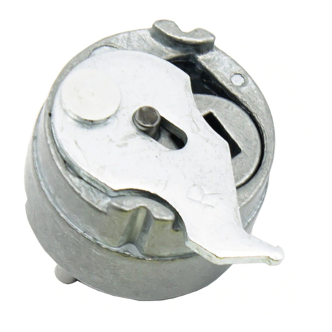
Dorma ES61 User manual

1. For new installations, surface mount ES61 strike first, then install exit device maintaining a minimum of
3⁄16” clearance.
2. Determine the horizontal centerline ‘G’ of the Pullman Latch on the exit device and transfer to frame
stop. (see Fig. 1)
3. Determine the distance ‘E’ from the door face to the vertical centerline ‘X’. (See Fig 1A.)
Measure from the push side of the door to determine the location of the vertical centerline ‘X’.
4. With the centerlines marked, now mark door jamb per template drawing and cut frame for
strike installation.
5. Insure that strike insert is placed in the center-most position on the strike faceplate prior to installation.
This allows maximum adjustability when installation is complete (see Fig. 2).
6. Connect wires from power source to terminal screws on strike (polarity is not observed).
7. Using slotted holes in chassis, install exit device electric strike with two (2) SHCS 1⁄4 - 20 x 1”, socket
head cap screws (provided).
8. Adjust chassis and electric insert (if necessary), horizontally, until pullman latch engages when door is
closed. Finally, tighten screws.
Important: Before proceeding to Step 9, be sure exit device dead locks when door is closed.
9. Mark, drill and tap for the locking screws provided, and install to secure final location with
two (2) SHCS 1⁄4 - 20 x 1”, screws (provided.)
Note:
If further adjustment is needed later, to correct door or weatherstrip misalignments, horizontally move
insert on its furrows by loosening screws under the face plate, and re-tighten when in the corrected
position (Fig. 2.).
Important:
The ES61 Electric Strike shall not be used as a door stop. Please install stops on frame in appropriate
locations. Ensure the exit device functions as intended for life safety concerns by verifying electric strike
and exit device compatibility. Maximum latch projection is essential to obtain full holding force.
© 2011 DORMA
USA: DORMA DRIVE, DRAWER AC, REAMSTOWN, PA 17567 PHONE: (800) 523-8483 (717) 336-3881 FAX: (717) 336-2106
INSTALLATION
ES61
Electric Strikes
PCN110055
R10/11SH
ISES61
08281160

Template For ES61 Strike
MEASUREMENT
FRACTIONAL INCHES
DECIMAL INCHES
METRIC mm
C 1- 5/8” 1.625 41.3
GHorizontal center line of
Pullman latch
K 4 -1/8” 4.125 105
M 1/4 - 20 Tap
O 5/16” .312 8
P 2-1/2” 2.5 63
Q 1- 3/8” 1.375 35
XVertical center line of
ES61
EDistance from door to vertical
centerline ‘X’
MODEL # ES61
X
G
S
M
M
O
P
C
Q
K
K
E
Exit
Device
Door
Edge
R
G
c
L
NOTE: DO NOT SCALE SPECIFICATIONS
SUBJECT TO CHANGE WITHOUT NOTICE.
Fig.1
Future alignment problems can be corrected by
loosening the two insert screws and moving the
insert horizontally across the furrows.
Original preparation is
not disturbed. (Fig.2).
© 2011 DORMA
USA: DORMA DRIVE, DRAWER AC, REAMSTOWN, PA 17567 PHONE: (800) 523-8483 (717) 336-3881 FAX: (717) 336-2106
ES61 Electric Strike Installation Instructions (Continued)
For these Devices: E =
For DORMA rim
exit device models
9300, F9300, 9700,
F9700
1-5/16”
For other device
manufacturers
R + 3/4”
Table of contents
Other Dorma Household Hardware manuals