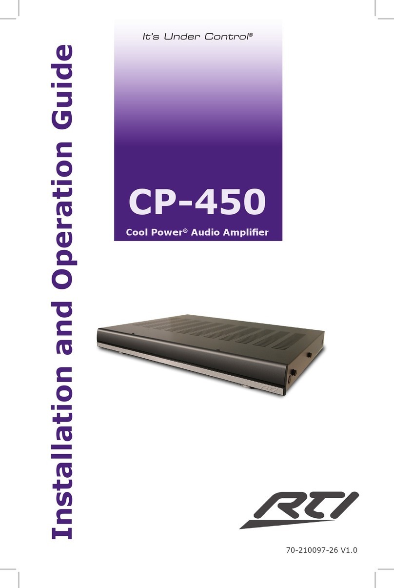
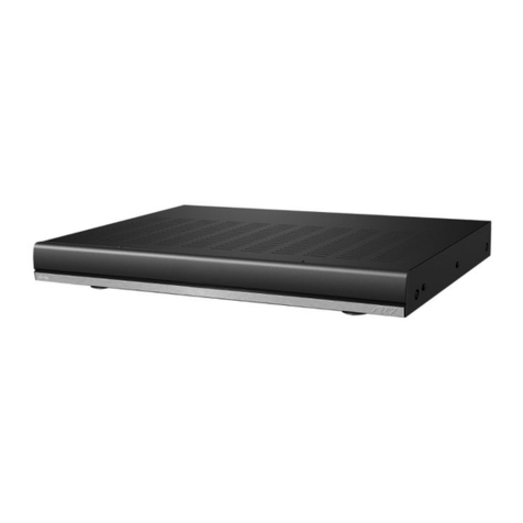
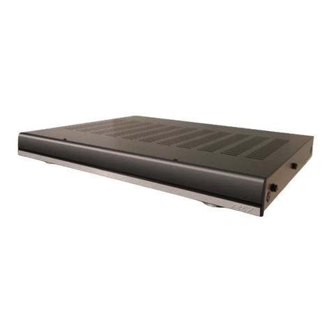
RTI Cool Power CP-16i Operating instructions

1
It’s Under Control®
Installation and Operation Guide
70-210209-21 V1.0
It’s Under Control®
CP-16i
Cool Power® Audio Amplier

Cool Power® Audio Amplier
CP-16i
22
Copyright © 2019
Remote Technologies Incorporated
All rights reserved.

3
It’s Under Control®
3
It’s Under Control®
This equipment has been tested and found to comply with the limits for a Class
B digital device, pursuant to Part 15 of the FCC Rules. These limits are designed
to provide reasonable protection against harmful interference in a residential
installation. Any changes or modications not expressly approved by the party
responsible for compliance could void the user’s authority to operate the device.
This equipment generates, uses, and can radiate radio frequency energy and, if
not installed and used in accordance with the instructions, may cause harmful
interference to radio communications. However, there is no guarantee that
interference will not occur in a particular installation.
If this equipment does cause harmful interference to radio or television
reception, which can be determined by turning the equipment o and on, the
user is encouraged to try to correct the interference by one or more of the
following measures:
Reorient or relocate the receiving antenna.
Increase the separation between the equipment and the receiver.
Connect the equipment into an outlet on a circuit dierent from
that to which the receiver is connected.
Consult the dealer or an experienced radio/TV technician
for help.
This device complies with Part 15 of the FCC Rules. Operation is subject to the
following two conditions:
1. This device may not cause harmful interference.
2. This device must accept any interference received including interference
that may cause undesired operation.
Industry Canada Compliance Statement
This device complies with Industry Canada license-exempt RSS standard(s).
Operation is subject to the following two conditions:
1. This device may not cause harmful interference.
2. This device must accept any interference received including interference
that may cause undesired operation.
Cet appareil est conforme avec Industrie Canada exempts de licence standard
RSS (s). Son fonctionnement est soumis aux deux conditions suivantes:
1. Ce dispositif ne peut causer des interférences nuisibles.
2. Cet appareil doit accepter toute interférence reçue y compris des
interférences qui peuvent provoquer un fonctionnement indésirable.
FEDERAL COMMUNICATIONS COMMISSION NOTICE
DECLARATION OF CONFORMITY (DOC)
The Declaration of Conformity for this product can be found on the RTI website
at: www.rticorp.com/declaration

Cool Power® Audio Amplier
CP-16i
4
Read Instructions. Read all safety and operating instructions before operating
the unit.
Retain Instructions. Keep the safety and operating instructions for future
reference.
Heed Warnings. Adhere to all warnings on the unit and in the operating
instructions.
Follow Instructions. Install and operate in accordance with the
manufacturer’s instructions.
Accessories. Only use attachments/accessories specied by the manufacturer.
Portable Cart Warning. Use only with the cart, stand, tripod, bracket, or
table specied by the manufacturer, or sold with the apparatus.
When a cart is used, use caution when moving the cart/
apparatus combination to avoid injury from tip-over.
Heat. Do not block any ventilation openings.
Heat. Keep the unit away from heat sources such as radiators,
heat registers, stoves, etc., including ampliers that produce
heat.
Power. Unplug this apparatus during lightning storms or when unused for long
periods of time.
Power Sources. Connect only to the power cord that was included with the
unit.
Power Outlet. Do not overload wall outlets or extension cords beyond their
rated capacity as this can cause electric shock or re.
Power Cord Protection. Route power supply cords so that they are not
likely to be walked on or pinched by items placed on or against them, paying
particular attention to the cords at plugs, at convenient receptacles, and at the
point at which they exit from the unit.
Power Cord Grounding Plug. Do not remove the grounding prong of the
grounding-type plug. A grounding type plug has two blades and a third
grounding prong. The third prong is provided for your safety. If the provided
plug does not t into your outlet, consult an electrician for replacement of the
obsolete outlet.
MAINS Outlet. Where MAINS outlets are used, the apparatus shall be
connected to a MAINS socket outlet with a protective earthing connection.
To completely disconnect this apparatus from the AC Mains, disconnect the
power supply cord plug from the AC receptacle.
MAINS Plug. Where the MAINS plug or an appliance coupler is used as the
disconnect device, the disconnect device shall remain readily operable.
Water and Moisture. Do not use the unit near water—for example, near a
sink, in a wet basement, near a swimming pool, near an open window, etc.
Object and Liquid Entry. Do not allow objects to fall or liquids to be spilled
into the enclosure through openings.
Cleaning. Clean only with dry cloth.
IMPORTANT SAFETY INSTRUCTIONS

5
It’s Under Control®
WARNING!
TO REDUCE THE RISK OF FIRE OR ELECTRIC SHOCK,
DO NOT EXPOSE THE UNIT TO RAIN OR MOISTURE.
Servicing. Do not attempt any service beyond that described in the operating
instructions. Refer all other service needs to qualied service personnel.
Damage Requiring Service. The unit should be serviced by qualied service
personnel when:
Objects have fallen or liquid has been spilled into the unit.
The power supply cord or the plug has been damaged.
The unit does not appear to operate normally or exhibits a marked change
in performance.
The unit has been dropped or the enclosure has been damaged.
IMPORTANT SAFETY INSTRUCTIONS

Cool Power® Audio Amplier
CP-16i
6
DISCLAIMER
All rights are reserved. No part of this document may be photocopied, reproduced, or
translated without the prior written notice of Remote Technologies Incorporated.
The information contained in this document is subject to change without notice.
Remote Technologies Incorporated shall not be liable for errors or omissions
contained herein or for consequential damages in connection with the furnishing,
performance, or use of this guide.
CP-16i, Integration Designer, and the RTI logo are registered trademarks of
Remote Technologies Incorporated.
Other brands and their products are trademarks or registered trademarks of their
respective holders.
iPod, iPod classic, iPod nano, and iPod touch are trademarks of Apple Inc., registered
in the U.S. and other countries.
Remote Technologies Incorporated warrants its products for a period of three (3)
years from the date of purchase from Remote Technologies Incorporated or an
authorized Remote Technologies Incorporated distributor.
This warranty may be enforced by the original purchaser and subsequent owners
during the warranty period, so long as the original dated sales receipt or other proof
of warranty coverage is presented when warranty service is required. Except as
specied below, this warranty covers all defects in material and workmanship in this
product. The following are not covered by the warranty:
Damage resulting from:
1. Accident, misuse, abuse, or neglect.
2. Failure to follow instructions contained in this Guide.
3. Repair or attempted repair by anyone other than Remote Technologies
Incorporated.
4. Failure to perform recommended periodic maintenance.
5. Causes other than product defects, including lack of skill, competence or
experience of user.
6. Shipment of this product (claims must be made to the carrier).
7. Being altered or which the serial number has been defaced, modied or
removed.
Remote Technologies Incorporated is not liable for any damages caused by its
products or for its failure of its products to perform, including any lost prots, lost
savings, incidental damages, or consequential damages.
Remote Technologies Incorporated is not liable for damages based upon
inconvenience, loss of use of the product, loss of time, interrupted operation,
commercial loss, any claim made by a third party or made by you for a third party.
Remote Technologies Incorporated’s liability for any defective product is limited to
repair or replacement of the product, at our option.
If any component of your CP-16i Audio Amplier needs service, please contact
Remote Technologies Incorporated by telephone or E-mail for return information.
Please do not return products to Remote Technologies Incorporated without
return authorization.
LIMITED WARRANTY
7
It’s Under Control®
Federal Communications Commission Notice.................................... 3
Safety Suggestions........................................................................... 4
Limited Warranty ............................................................................. 6
Disclaimer ........................................................................................ 6
Table of Contents ............................................................................. 7
Chapter 1 - Welcome ........................................................................ 8
- Important Notes ..................................................................... 8
- Product Contents .................................................................... 9
Chapter 2 - Features and Description .............................................. 10
- Front Panel ............................................................................ 10
- Rear Panel ............................................................................. 11
Chapter 3 - Installation and Operation ............................................ 12
- Controlling the CP-16i............................................................ 12
- Mounting ............................................................................... 12
- Wiring and Connections ......................................................... 13
- I/O Control Input Port........................................................... 18
- Powering the CP-16i .............................................................. 23
Chapter 4 - Specications................................................................ 24
Chapter 5 - Service and Support...................................................... 26
TABLE OF CONTENTS

Cool Power® Audio Amplier
CP-16i
8
Thank you for using the CP-16i Cool Power® Audio Amplier.
Ideal for the discerning listener, the CP-16i Audio Amplier utilizes Cool Power®
technology for superb sonic performance. Featuring 16 channels of audiole-
grade sound, the powerful amplier delivers 100 watts per channel, easily
expanding the entertainment reach of any audio distribution system. For
additional boost, bridge-mode is available, doubling the output to an incredible
200 watts per channel. Engineered to perform as well as it sounds, the CP-16i
utilizes highly-ecient Class-D amplier technology and has a compact chassis
design that requires only one (1RU) rack space.
RTI ampliers enhance the listening experience, delivering crystal clear, high
quality sound to every room. Matched with the RTI control ecosystem, you have
a complete solution for distributed audio in residential and commercial spaces.
Go ahead and put RTI technology to the test - you’ll never miss a beat.
IMPORTANT NOTES
Please read these important notes about the CP-16i:
The CP-16i should be placed in an area where it is around normal room
temperature (between 60°F to 90°F).
Avoid installing the CP-16i in a location with little or no air circulation.
Avoid installing the CP-16i in a location where it can come in contact with
direct sunlight.
Do not let the CP-16i system get wet. It should not be handled with wet
hands or placed in an area where it could get wet.
Do not subject the CP-16i to smoke, dust, or vibrations.
Only use the power cord that is supplied with the CP-16i. Using the wrong
type of power cord may result in damage.
Do not disassemble the unit. Service of the CP-16i should be performed by
authorized personnel only.
CHAPTER 1 | WELCOME

9
It’s Under Control®
Contents within the box include the following items:
One (1) CP-16i Cool Power® Audio Amplier
One (1) CP-16i Faceplate
Two (2) Rack Mounting Ears with Screws
Four (4) Feet with Screws
Eight (8) Speaker Terminal Blocks
One (1) IO Port Terminal Block
One (1) Power Cord
One (1) Installation Guide
UNPACKING AND INSPECTION
After unpacking the CP-16i Audio Amplier, save all of the packing materials in
case you ever have to ship the unit.
Thoroughly inspect the CP-16i and packing materials for signs of damage.
Report any damage to the carrier immediately. Report any equipment
malfunctions to RTI or an authorized RTI distributor.
CHAPTER 1 | PRODUCT CONTENTS

Cool Power® Audio Amplier
CP-16i
10
CHAPTER 2 | FEATURES AND DESCRIPTION
FEATURES
• Superior Performance – Utilizes proven audio amplication technology to
deliver premium sonic performance.
• Easy Expansion – 16 channels available for all kinds of zoning
congurations in large or far reaching the properties.
• Power & More Power– 100 watts per channel at 4 ohms / 200 watts at 8
ohms bridged.
• Compact Design – At just 1RU high, the CP-16i leaves room to install
more components in the rack.
• Ultra-Ecient – Cool Power® Class D amplier technology ensures
ecient heat dissipation and low power consumption.
NOTES:
• Note that the CP-16i requires an external preamp for volume control.
• The CP-16i also supports a Bridge Mode (BTL) conguration. Bridge Mode
converts one stereo pair into a single, stronger amplication channel. If
all Zones are bridged, there are 8 channels available. Stereo and Bridged
Zones can be mixed as necessary.
Front Panel Components (LEDs)
The front panel features three LEDs.
POWER LED (Green/Red)
The Power LED indicates that the current power state of the amp:
• Green indicates that the amplier is On.
• Red indicates that the amplier is receiving power, but is in Standby mode.
OC/CLIP LED (Yellow/Red)
The OC/CLIP LED indicates that either the current of one or more of the speaker
outputs has exceeded its maximum or that the power supply is overloaded.
NOTE: The amplier outputs are limited to 20A peak each in order to protect
the power stages against overload during a short circuit, or over-current event
on the output of the amplier.
• Yellow indicates an OC (over-current) shutdown of the amplier output.
In the case of an OC event, the amplier will shut down to protect itself,
and indicate an OC event on this LED (yellow) and the OC pin (pin 8 on
the 10-pin I/O port - see page 15). An OC event can indicate a cable fault,
installation fault or defective speaker.
POWER OC/CLIP THERMAL
Cool Power Audio Amplifier
Model CP-16i
®

11
It’s Under Control®
CHAPTER 2 | FEATURES AND DESCRIPTION
CP-16i REAR PANEL COMPONENTS
• Red indicates an overload event with the Power Supply. The LED will
light red if internal temperature sensors on the power supply sense an
abnormally high temperature, or if power supply over-current/over-load/
power-limit circuits are triggered. In either case, the power supply will
limit the amplier output to keep the power supply within safe limits, while
keeping the music playing.
THERMAL LED (Red)
The Thermal Protection LED indicates thermal shutdown of the individual zones
(amplier boards).
• The temperatures of all the output channels are individually monitored,
and if one or more of them reaches the thermal limit (105°C) then the
respective Zones will shut down and go into soft start mode (Channels 1/2
= Zone 1, Channels 3/4 = Zone 2, etc), and the Thermal Protection LED
will be lit.
• The other Zones will continue to be active. When the temperature has
dropped below the thermal threshold, the respective Zone(s) start up again
automatically.

Cool Power® Audio Amplier
CP-16i
12
CHAPTER 3 | INSTALLATION AND OPERATION
Controlling the CP-16i
The CP-16i can be powered on and o externally by using the two signals
12V trigger and 3-5V trigger. A Signal Sense function is also provided which
automatically can switch on the CP-16i in the event of an audio signal and
switch o the CP-16i to enter standby mode when no audio signal has been
present on the signal terminals for approximately 13 minutes.
NOTE: Volume control for the CP-16i is managed by an external pre-amp or
audio switcher.
Installation
Mounting the CP-16i into an Equipment Rack
The CP-16i can be mounted in a 19” equipment rack or on a solid at
surface. Use the included removable rack ears and removable feet for
mounting.
Ventilation
NOTE: The maximum operating ambient temperature is 45°C (113°F).
• To ensure that the rack enclosure is adequately ventilated, there must
be a minimum of 3” all around the CP-16i unit.
• Sucient airow must be achieved (by convection or forced-air cooling)
to satisfy the ventilation requirements of all the items of equipment
installed within the rack.
Rack Mount Safety Instructions
• Mounting of the equipment in the rack should be such that a hazardous
condition is not achieved due to uneven mechanical loading.
• Consideration should be given to the connection of the equipment to the
supply circuit and the eect that overloading of the circuits might have
on over current protection and supply wiring. Appropriate consideration
of equipment nameplate ratings should be used when addressing this
concern.
• Reliable grounding (earthing) of rack-mounted equipment should be
maintained. Particular attention should be given to supply connections
other than direct connections to the branch circuit (e.g. use of power
strips).

13
It’s Under Control®
CHAPTER 3 | INSTALLATION AND OPERATION
Wiring and Connections
IMPORTANT NOTE: The amplier must be turned o whenever you make
changes to the input connections and speaker wire connections.
Connecting Audio Source Devices
Source Devices connect to the Audio (Signal) Inputs connectors on the rear
panel.
Audio (Signal) Inputs
The following table provides pinout information for the Audio Inputs:
SE/BTL (Stereo/Bridge Mode) Switches (1-8)
Eight SE/BTL slide switches (located between the two RCA/phono input
connectors for each Zone). These switches provide the ability to set each of
the eight Zones to either Stereo Mode (SE) or Bridge Mode (BTL). Note that by
default, all Audio Inputs are set to Stereo Mode.
• Stereo Mode (SE): In Stereo Mode, both channels are used for stereo
audio input. Stereo mode provides true stereo separation between the left
and right channels in each Zone.
• Bridge Mode (BTL): Bridge Mode uses one input channel of the amplier
to combine the power from both channels output into one single output.
In Bridge Mode, the odd channels are used for audio input and the even
channels are disconnected internally.

Cool Power® Audio Amplier
CP-16i
14
CHAPTER 3 | INSTALLATION AND OPERATION
Connecting Input Devices in Stereo Mode
Stereo input devices use both input channels (left and right) for each Zone.
• Odd-numbered channels (with white connectors) should be used to
connect to the left output on the source device.
• Even-numbered channels (with red connectors) should be used to connect
to the right output on the source device.
The CP-16i supports up to eight stereo input devices, each one associated with
an input Zone (1-8). Note that each Zone represents a stereo pair. For example,
Zone 1 consists of CH1 (left channel) and Ch2 (right channel).
There is a direct correlation between the audio inputs and the speaker outputs.
For example, a stereo device connected to the Zone 1 inputs (CH1 and CH2)
will output on the CH1 (left) and CH2 (right) speaker outputs:
NOTE: When connecting stereo input devices, verify that the Stereo/Bridge
(SE/BTL) mode switch for the Zone is set to “SE”. This is the default factory
setting.
Connecting Input Devices in Bridge Mode
In Bridge Mode, input devices connect to the left input channels only. Note that
left input connectors are white, and are the odd-numbered channels (CH1, 3, 5,
7, 9, 11, 13 and 15).
There is a direct correlation between the audio inputs and the speaker outputs.
For example, a bridged device connected to the Channel 1 input (CH1) will
output on the CH1 (left) and CH2 (right) speaker outputs:
NOTE: When connecting bridged input devices, verify that the Stereo/Bridge
(SE/BTL) mode switch for the Zone is set to “BTL” as shown above
CP-16i Inputs (Bridge Mode) CP-16i Outputs (Bridge Mode)
CP-16i Inputs (Stereo Mode) CP-16i Outputs (Stereo Mode)

15
It’s Under Control®
CHAPTER 3 | INSTALLATION AND OPERATION
Connecting Speakers
All speaker connections must use Class 2 Wiring. Class 2 Wiring is required
due to the fact that power is above 10W per channel under normal operating
conditions.
Speakers connect to the captive-wire output terminals (CH1-CH16) on the rear
panel:
Each Zone (1-8) consists of two channels (an L/R pair in Stereo Mode),
and each Channel (1-16) uses a 2-pin captive-wire connector to connect to
speakers.
NOTE: For wiring runs longer than 80 feet, 14-gauge speaker wire is
recommended.
Speaker Output Connectors
The speaker output connectors consist of two 16 pin captive-wire terminals;
each of the output terminals having a “+” and “-“ terminal.
The label “BTL” on each speaker pair points to the pins that are used when
connecting a single speaker to an input in Bridge Mode.
The following table provides pinout information for the Speaker Output
Terminals

Cool Power® Audio Amplier
CP-16i
16
CHAPTER 3 | INSTALLATION AND OPERATION
Connecting Speakers in Stereo Mode
NOTE: When connecting stereo speakers, verify that the Stereo/Bridge (SE/
BTL) mode switch for the associated Zone is set to “SE”.
Stereo speaker pairs use both output channels (left and right) for each Zone.
• Odd-numbered channels should be used to connect to the left speaker.
• Even-numbered channels should be used to connect to the right speaker.
The CP-16i supports up to eight stereo speaker pairs, each one associated with
a Zone (1-8). This diagram illustrates the wiring connection from both Zone
output channels to a stereo speaker pair:
NOTE: If incorrect wiring is used there is a risk of electrical shock and a re
hazard.
The table below illustrates the direct correlation between the audio inputs and
the speaker outputs in Stereo Mode:

17
It’s Under Control®
CHAPTER 3 | INSTALLATION AND OPERATION
Connecting Speakers in Bridge Mode
NOTE: When connecting a speaker to a “bridged” input, verify that the Stereo/
Bridge (SE/BTL) mode switch for the associated Zone is set to “BTL”.
In Bridge Mode, both channels in a Zone are connected to a single speaker, via
the positive (“+”) pins for both output channels:
NOTE: If incorrect wiring is used there is a risk of electrical shock and a re
hazard.
The table below illustrates the direct correlation between the audio inputs and
the speaker outputs in Bridge Mode:

Cool Power® Audio Amplier
CP-16i
18
CHAPTER 3 | INSTALLATION AND OPERATION
I/O (Control Input) Port
The 10-pin captive-wire I/O (Control Input) port is for external control and
status indication.
10-pin I/O (Control Input) Port with External Signal Sense switch
The following table lists the pinouts for the I/O port

19
It’s Under Control®
CHAPTER 3 | INSTALLATION AND OPERATION
The function of each pin on the I/O port is described below.
Pin 1 - Signal Sense
Pin 1 on the 10-pin I/O port is used for single-ended Signal Sense input (+).
This pin detects an input signal from a source device when the source device
is active. Pin 1 (Signal Sense +) connects to one of the source device’s input
cables to provide a signal to the CP-16i when the source device is active.
Pin 2 - Signal Sense Input Ground
Pin 2 on the 10-pin I/O port is used for Signal Sense input ground (-).
PIN 1 Example - Signal Sense Connection (Unbalanced)
External Signal Sense Switch
With the External Signal Sense switch in the ON position, the amplier is
automatically turned on when an audio signal is present, and automatically
placed in standby mode when no audio signal has been present on the signal
terminals for approximately 13 minutes.
• Note that the example diagram indicates the Signal Sense connection tied
to the Left output from the source device, but Signal Sense can come from
either output.
• The amplier will power up if a signal is applied to the signal sense input.
By default, the External Signal Switch is set to the ON position.
Pin 3 - 12V (In) Trigger
The CP-16i can be turned On or placed in Standby mode externally via a 12V
Trigger signal. A 12V trigger input is accessible via Pin 3 on the 10-pin I/O port.

Cool Power® Audio Amplier
CP-16i
20
CHAPTER 3 | INSTALLATION AND OPERATION
Pin 4 - Trigger (Loop Out)
The CP-16i also provides a convenient way to daisy-chain a 12V trigger to other
devices. Any voltage provided to Pin 3 is looped out to Pin 4 of the 10-pin I/O
port:
Pin 4 = 12V Trigger (Out)
I/O port on
rst amplier
Pin 10 = Status GND
I/O port on
downstream
Pin 3 = 12V Trigger In Pin 10 = Status GND
PIN 4 Example - Trigger (Loop Out) Connections
Pin 4 connects to a +12V Trigger (input) on a downstream amplier
NOTE: Pin 3 and Pin 4 are hard wired together. Therefore, when a trigger is
applied to pin 3 it will also be present at pin 4. Pin 4 will be high only if a signal
is applied to Pin 3.
Pin 5 - Local/Trigger GND
Pin 5 on the 10-pin I/O port provides a ground connection for the 3-5V Logic
Level Trigger. Pin 5 connects to the GND pin of an I/O port on an external
controller.
Pin 6 - 3-5V Logic Level Trigger
The CP-16i can be also turned On or placed in Standby mode externally via a
3-5V Logic Level trigger signal. A 3-5V trigger input is accessible via Pin 6 on
the 10-pin I/O port.
3-5V Trigger Switch
The 3-5V Trigger Switch has two selections; High and O.
When the 3-5V Trigger Switch is set to High, the amplier will turn on when AC
mains is turned on, For example, the 3-5V Trigger switch could be set to High
if the amplier needs to be forced on without having signal sense or external
trigger signals.
Table of contents
Other RTI Amplifier manuals

RTI
RTI VMX-16 User manual

RTI
RTI AMR-350 User manual

RTI
RTI AMV-340 User manual

RTI
RTI AMV-340 User manual

RTI
RTI AMR-220 User manual

RTI
RTI CP-1650 Original operating instructions

RTI
RTI VHX-4 User manual

RTI
RTI AD-4 Operating instructions

RTI
RTI Cool Power CP-450 Operating instructions

RTI
RTI AD-4x Operating instructions