Rugged Computing ATLAS slim 14 User manual

Rugged Industrial
Portable Computer
System Assembly Manual
A Technical Manual for System Integrators and Service
Technicians

The information contained in this document is believed to be accurate. However, no
responsibility is assumed for its use, nor for any infringements of patents or other rights
of third parties which may result from its use. This information is subject to change
without notice.
This manual is divided into 5 parts:
1. Getting Started
2. Opening to Chassis
3. Assemble the System
4. Using the System Controls
5. Appendix
Each part may be referenced individually, however, it is highly recommended for first
time users to go through all parts sequentially to obtain an overall understanding of the
system.
1

CONTENTS
Getting Started………………………………………………………………………………..4
Before you Start………………………………………………………………………………..5
Precautions……………………………………………………………………………………..6
Power Connections…………………………………………………………………………..6
Ventilation……………………………………………………………………………………..6
Care for the LCD……………………………………………………………………………...6
Tools and Supplies Needed………………………………………………………………...…7
Subassembly Contents…………………………………………………………………………7
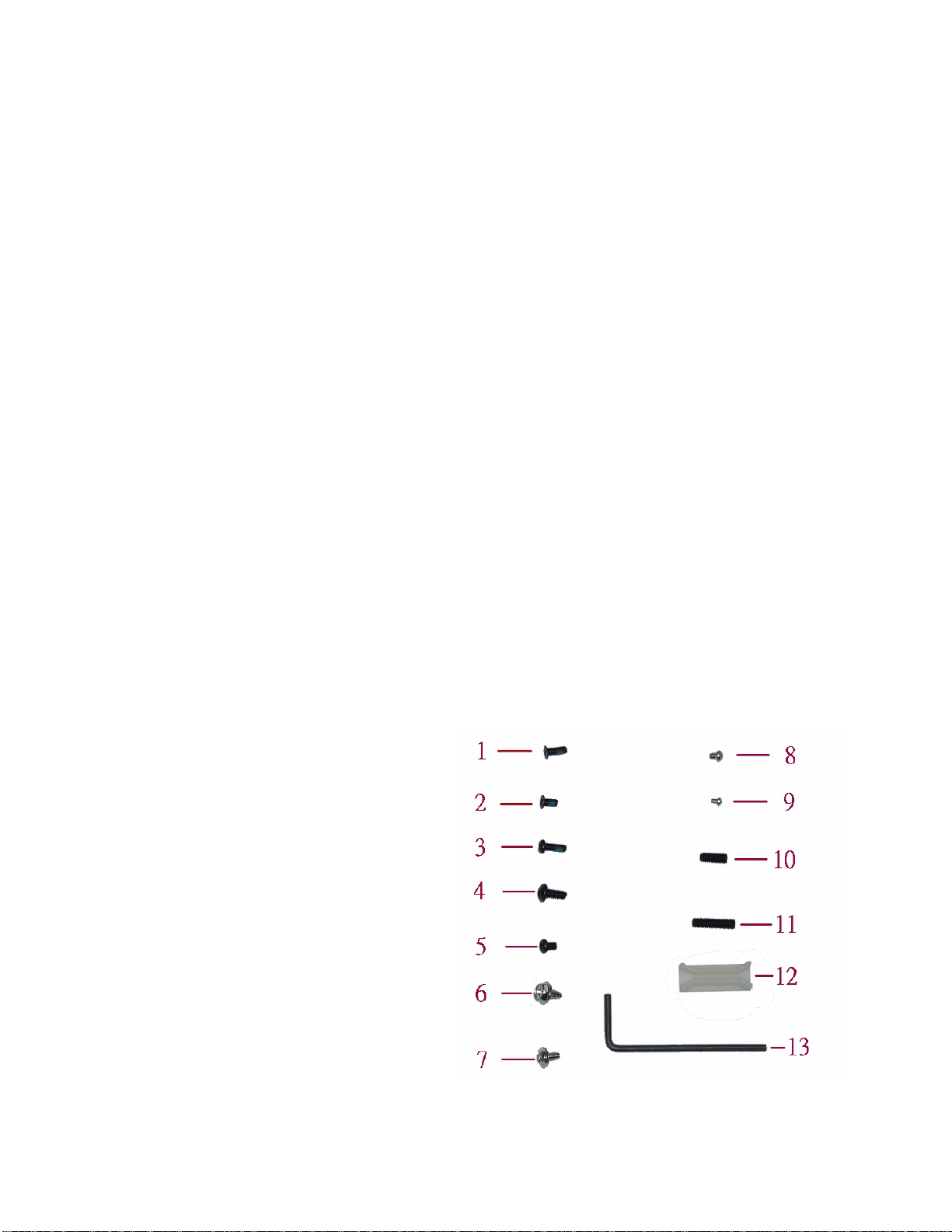
Parts Contents…………………………………………………………………………………..7
Identifying Parts and Controls…………………………………………………………………8
Opening the Side Access Covers……………………………………………………………8
Removing Side Covers…………………………………………………..……………………..8
Slim Model Side Views…….. …………………………………...……………………………..8
Front View………………………………………………………………………………..…….10
Detaching the Keyboard………………………………………………………………………11
Opening the Chassis……………………………………………………………………...…12
Removing the Back Cover……………………………………………………………………13
Identifying the Internal Parts……………………………………………………………….....14
Removing the Drive Carriers…………………………………………………………………14
Removing the Power Supply…………………………………………………………………16
Removing the PICMG backplane board…….…………………………………………17
Removing the Slot Positioner metal bracket……………………………………………18
Assemble the System…………………………………………………………………….....19
Installing the PICMG and CPU card………………………………………………….…19
Installing CPU card with the PICMG backplane into the case……………………….....20
Installing the CPU card stabilizer…………………………………………………………22
Installing the ATX Enable cable……………….……………………………………22
2

Installing the interface card……………………………………………………………….24
Installing the interface card Support……………….…………………………………….25
Installing the Power Supplier And All Cables From CPU card……………………………27
Installing the Drive Assembly…………………………………………………………………29
Installing Parallel and Serial connector……………………………………...………………33
Keep Cleanness Area to prevent conflict with back Fan………………………….……34
Cover the Back case…………………………………………………………………….……35
Using the System Controls………………………………………………………………..36
Starting your System…………………………………………………………………………37
OSD Controls…………………………………………………………………………………37
Adjusting the OSD Parameters……………………………………………………………....38
Appendix……………………………………………………………………………………….39
Specifications…………………………………………………………………………………40
General Features……………………………………………………………………………40
Display Selection……………………………………………………………………………40
Environment…………………………………………………………………………………40
Dimensions & Weight………………………………………………………………………40
Troubleshooting Techniques…………………………………………………………………41
3

1. Getting Started
Before you Start………………………………………………………………………………....5
Precautions………………………………………………………………………………………6
Power Connections……………………………………………………………………………6
Ventilation…………………………………………………………………………………...….6
Care for the LCD………………………………………………………………………………6
Tools and Supplies Needed……………………………………………………………………7
Subassembly Contents…………………………………………………………………………7
Parts Contents…………………………………………………………………………………7
Identifying Parts and Controls…………………………………………………………………8
Opening the Side Access Covers……………………………………………………………8
Removing Side Covers………………………………………………………………………8
Side View…………………………………………………………………………………….…10
Front View……………………………………………………………………………………...11
Detaching the Keyboard………………………………………………………………………11
4

Before You Start
The major component of the subassembly is the chassis. The chassis comes pre-
assembled with:
• An Active Matrix LCD
• LCD Controller
• An PICMG backplane board with 2 PCI slots ( one 338mmX 118 , one half
size 175mm X 118) or 1 ISA((Max length 338 X 118mm)
• Power Supply
• Keyboard
• Ventilation fans
• Internal Speaker
To complete the System, you must add a PICMG CPU board, and peripheral devices.
Before adding these devices, it is important to follow certain basic safety precautions.
You should become familiar with the chassis both externally and internally. And you
should also have the right tools available to you.
5

Precautions
Power Connections
Use the Supplied Power Cord
The subassembly is shipped with a power cord compatible with the AC wall outlet
in your region.
Power Supply Type
Before plugging in the power cord, examine your power supply to see if you have
an autosensing or non-autosensing power supply.
Autosensing power supplies will automatically adjust to the AC outlet voltage. A
non-autosensing power supply comes with a voltage selector switch located near
the AC power connector. Make sure it is set to the appropriate voltage setting for
your power outlet.
1U Power Supply Switch
The power supply shipped with the chassis may or may not have an ON/OFF
switch. If your power supply has an ON/OFF switch, you must first press the
switch to the ON position to use power up/down button located on the front.
Note: The power up/down button located on the front of the chassis DOES NOT
turn off AC power. You must unplug the AC power cord from the AC outlet or the
chassis to remove AC power from your system.
Ventilation
The chassis comes with one intake fan, one exhaust fan and one power supply
exhaust fan.Never block any of the ventilation openings while the system is
operating. Always leave enough room around the chassis to allow adequate air
flow.
Care for the LCD
The chassis comes with a pre-assembled active matrix LCD. Liquid crystal
displays are made of glass which will break or crack if mishandled. During
system assembly, keep the keyboard latched to the chassis. The keyboard
housing is constructed of metal and provides front impact protection for the LCD
during transportation.
6

Tools and Supplies Needed
Before beginning your work, make sure you have the following tools and supplies
available:
• A #2 Phillips (cross head) screwdriver.
• An anti-static wrist strap (recommended).
Subassembly Contents
The subassembly consists of:
• This subassembly guide.
• Chassis with pre-assembled LCD, LCD controller, power supply,
cooling fans, internal speaker and keyboard with integrated pointing
device.
• An PICMG backplane board with 2 PCI slots or 1 ISA slot
• Power cord
• Carrying case
• Parts for installing the motherboard and drives
See Appendix for technical specifications.
Parts Contents
The subassembly parts kit
contains the following
hardware for installing
boards and drives.
Type# Specification
1. M3x0.5x8 Nylok®
2. M3x0.5x6 Nylok ®
3. M3x0.5x8 Nylok®
4. #6 – 32x10
5. M3x0.5x4
6. #6 – 32x6 (w/washer)
7. M3x0.5x6 (w/washer)
8. M2.6X3
9. M2X3
10. M4x0.7x8
11. M4x0.7x16
12. Interface card Support
13. Hexagon Spanner
7

Identifying Parts and Controls
Opening the Side Access Covers
The side access covers provide side impact protection for the I/O ports and drive
bays. The access covers must be opened to access I/O connectors.
Turn the thumbscrew in the counter-clockwise direction to open the access
covers. The covers are hinged to the chassis and will swing open.
Side Views
8

Use the photos below to identify the components and I/O ports that are accessible
from the two sides of the chassis. The illustration shows the external connectors
and components of a completely assembled system. Your subassembly has only
knockout holes instead.
On the left side of the chassis you
will find the following:
1. Filtered Intake Fan
2. Keyboard latch
3. Internal Speaker
4. Power connector
5. External Power Switch
On the right side of the chassis
you will find the following:
1. Keyboard latch
2. Slim CD ROM Drive Bay
3. Keyboard
4. Internal Speaker
5. 3.5” FDD Drive
6. Expansion slot outlet
9

You access the front panel controls by first disengaging the keyboard. Disengage the
keyboard from the chassis latches by sliding the latch tabs on both sides of the chassis
upwards as shown, and simultaneously pulling the top part of the keyboard away from
the chassis.
The keyboard is still
hinged on the bottom by
latch bolts.
Lay down the keyboard.
If you wish, you may
use the tilt-up feet
located on the bottom o
f
the chassis.
Note: The keyboard will fall down once the latch tabs have been released. You MUST
support the keyboard when releasing the latches.
Chassis Front View
10

Detaching the Keyboard
The keyboard is normally hinged to the chassis via two latch bolts located on the
top of the keyboard. You can detach the keyboard by sliding both release pegs
towards each other and compressing the latch bolts until they slide out of the
slots. Pull the keyboard away from the chassis and release the pegs.
To reattach the keyboard, push the latch bolts in as indicated below. Then insert
the keyboard in the chassis and release the latch bolts. The latch bolts should
lock in the chassis.
Note: Once the keyboard has been
removed from the chassis, you can
use the keyboard tilt up feet to tilt
the keyboard as shown on the right.
11

2. Opening the Chassis
Removing the Back Cover……………………………………………………………………13
Identifying the Internal Parts……………………………………………………………….....14
Removing the Drive Carriers…………………………………………………………………14
Removing the Power Supply…………………………………………………………………16
Removing the PICMG backplane board…….…………………………………………17
Removing the Slot Positioner metal bracket……………………………………………18
12

Removing the Back Cover
You must first remove the back cover to work on the interior of the chassis.
Please observe the following safety guidelines when removing the back covers:
• Always power down the system.
• Always turn off any peripheral device connected to the system.
• Always unplug the AC power cord from the chassis.
Position the chassis so that the back is facing you. Remove all the release
screws as shown below. There are 8 screws along the perimeter of the back
cover that secures it to the chassis. Once you have removed all 8 screws, you
can now remove the back cover from the chassis. CAREFUL! The back cover fan
may be connected to a chassis power supply connector. Make sure you
disconnect the fan from this connector before fully removing the back cover. The
screws used on the back cover are #1 screws (refer to page. 7)
13

Identifying the Internal Parts
1. Power Supply
2. PICMG backplane
3. Drive Bay Carrier
Remove everything inside the case
Before install the PICMG CPU card or and expansion card, all the parts inside the
case have to be removed, There are following main parts need to be move out:
1. Power Supply
2. PICMG backplane
3. Drive Bay Carrier.
4. Slot Positioner metal bracket
A. Removing the Drive Carrier
The chassis contains one drive carrier which supports 3.5” FDD drives, a hard
drive and a Slim-Type CD-ROM.
Remove all 4 screws as shown at right picture .
There are 4 screws inside the case that
secures it to the chassis as shown at right
picture. #3 screw (refer to page. 7)
14

There are also have 2 screws along the left
side of case(if LCD face to you) that secures
it to the chassis as shown at right picture.
Once you have removed all 4 screws, you can
now remove the Driver Carrier from the chassis.
#3 screw (refer to page. 7)
To remove the Driver Carrier from the chassis
, move Carrier as the arrow Sign-1 to let it’s right side apart from the case, to move it
out complete from the case just move the Carrier down as shown Sign-2 arrow shown
at the picture.
15

B. Removing the Power Supply
There are have 2 screws along the right
side of case(if LCD face to you) that secures the
power supplier to the chassis as
shown at left picture. #6 screw (refer to page. 7)
There are also have 2 screws along the bottom side of case that secures the power
supplier to the chassis as shown at left picture. The picture show 1,2, and 3 screws, but
normally it only have screws 1 -2 or 2-3 depends on the power supplier’s model.
Once you have removed all these screws, you can now remove the Power Supplier
from the chassis. #3 screw (refer to page. 7)
(Bottom view)
16

C. Removing the PICMG backplane board
There is a PICMG backplane board which already on a metal Carrier.
You need to remove the Carrier out by unscrew all the 6 screws as following picture.
But keep the PICMG board mounted on the metal Carrier. #5 screw (refer to page. 7)
17

D. Removing the Slot Positioner metal bracket
The Slot Positioner metal bracket as shown at
left picture which is used to screw the CPU card
and all expansion cards. This metal bracket need
to be removed before install the PICMG board.
To remove this bracket , check with left picture
There are 4 screws at the left side of the case
And 1 screw inside the case need to be removed
Once you have removed all 5 screws, you can
now remove the Slot Positioner metal bracket
from the chassis. #3 screw is hole1-4 ,
#5 screw is hole 5(refer to page. 7),
A Clean and empty case, ready to install all parts.
18

3. Assemble the System
The normal procedure for Installing as complete system should follow following steps
A. Installing the PICMG and CPU card
B. Installing CPU card with the PICMG backplane into the case
C. Installing the CPU card stablizer
D. Installing ATX Power Enable cable
E. Installing the interface card
F. Installing the interface card Support
G. Installing the Power Supplier And All Cables From CPU card
H. Installing the Drivers.
I. Installing Parallel and Serial Connector
J. Keep Cleanness Area to prevent conflict with back Fan
K. Cover the Back case
.
A. Preassemble the PICMG board ,CPU card and Slot
Positioner into a module
Keep the PICMG board with the board Carrier together and plug the PICMG CPU
card into the PICMG slot. After CPU board is plugged, screw the Slot Positioner
metal bracket to the CPU board with a M4X8 screw show at the red circle of the
following picture. This M4X8 screw is big enough for hand with a screw driver to
work
.
19
This manual suits for next models
1
Table of contents
Other Rugged Computing Laptop manuals
Popular Laptop manuals by other brands

Core Innovations
Core Innovations CLT146401 user manual

Toshiba
Toshiba Portege Z20-B Series user guide

Phoenix Gold
Phoenix Gold pmn user manual

HP
HP 3105m Maintenance and service guide

Lenovo
Lenovo THINKPAD X30 Guía de servicio y de resolución de problemas

Lenovo
Lenovo Lenovo 3000 J Series Safety and Warranty Guide