Rupes BH252R User manual

BH252R
Martello perforatore pneumatico BH252R
BH252R Pneumatic Drill Hammer
Perforateur pneumatique BH252R
Pneumatik-Bohrhammer BH252R
Martillo perforador conpercutor neumático BH252R
Электропневмоперфоратор BH252R
Pneumatikk-borhammer BH252R
MANUALE D'ISTRUZIONI
OPERATING INSTRUCTIONS
MODE D' EMPLOI
GEBRAUCHSANWEISUNG
MANUAL DE INSTRUCCIONES
УЯ О ЭУАА
AANWIJZINGEN VOOR HET GEBRUIK EN HET ONDERHOUD
librettoBH252R 21-08-2007 9:30 Pagina 1

MARTELLO PERFORATORE
PNEUMATICO BH252R
(VEDERE FIGURE A PAG. 25-26)
Applicazione
Il martello perforatore pneumatico può essere uti-
lizzato in maniera universale per forature a mar-
tello, per leggeri lavori di scalpellatura su pietra
nonchè per forare ed avvitare viti nel legno, nel
metallo ed in materiale plastico.
1. INDICAZIONI DI SICUREZZA E MISURE
ANTINFORTUNISTICHE
Prima di mettere la macchina in esercizio, legge-
re completamente le Istruzioni per l’uso, rispetta-
re le indicazioni di sicurezza contenute nella pre-
sente Istruzione nonchè le indicazioni generali di
sicurezza per macchine elettriche riportate nel-
l’opuscolo allegato.
Qualora durante l’operazione di lavoro venis-
se danneggiato il cavo di rete, estrarre imme-
diatamente la spina dalla presa della corren-
te.
Mai lavorare con un cavo di rete danneggia-
to.
Portare gli occhiali, la cuffia ed i guanti di pro-
tezione, nonchè scarpe di sicurezza.
Indossare una protezione acustica.
L'effetto del rumore può causare la perdita
dell'udito.
Utilizzare le impugnature supplementari
fornite in dotazione con la macchina. La
perdita di controllo della macchina può provo-
care incidenti.
Non lavorare su materiale contenente amianto.
Non trasportare la macchina tenendola per il
cavo.
Le prese in ambienti esterni devono essere
assicurate tramite un interruttore di sicurezza
per correnti di guasto (FI).
Non è permesso perforare la carcassa della
macchina al fine di volerla contrassegnare.
L’isolazione di protezione viene ponticellata.
Utilizzare targhette autoincollanti.
Se la punta dovesse bloccarsi inaspettata-
mente, la macchina reagisce con contraccol-
pi. Mantenere perciò sempre una distanza di
sicurezza e tenere bene la macchina con
entrambe le mani.
2. FIGURA
1Attacco utensili
2Protezione antipolvere
3Boccola di sbloccaggio
4Commutatore rotante
5Feritoia di ventilazione
6Commutatore per la reversibilità
7Pulsante di bloccaggio per interruttore di
inserimento/disinserimento
8Interruttore di inserimento/disinserimento
comando numero di giri
2
ITALIANO
Martello perforatore pneumatico BH252R 2
ENGLISH
BH252R Pneumatic Drill Hammer 5
FRANÇAIS
Perforateur pneumatique BH252R 8
DEUTSCH
Pneumatik-Bohrhammer BH252R 12
ESPAÑOL
Martillo perforador conpercutor neumático BH252R 15
У
Электропневмоперфоратор BH252R 18
NEDERLANDS
BH252R Pneumatikk-borhammer 21
MANUALE D'ISTRUZIONI
OPERATING INSTRUCTIONS
MODE D'EMPLOI
GEBRAUCHSANWEISUNG
MANUAL DE INSTRUCCIONES
УЯ О ЭУАА
AANWIJZINGEN VOOR HET GEBRUIK EN HET ONDERHOUD
Italiano
Fet
t
3
Fet
t
3
Fet
t
3
Fet
t
3
Fet
t
3
Fet
t
3
Fet
t
3
librettoBH252R 21-08-2007 9:30 Pagina 2

9Selettore Foratura / Foratura a martello
10 Attacco per battuta di profondità
Accessori illustrati o descritti non fanno neces-
sariamente parte del volume di consegna.
3. DA TI TECNICI
Potenza assorbita 700 Watt
Num. giri a vuoto 0-1170 1/min.
Num. percussioni a vuoto max 5270 1/min.
Potenza della percussione 2,5 Joule
Campo di foratura consigliato per foratura a
martello Ø 4-16 mm
Foratura a martello nel calcestruzzo Ø 24 mm
Foro massimo acciaio Ø 13 mm
Foro massimo legno Ø 30 mm
Diametro collare Ø43 mm
Peso 2,6 Kg
4. INFORMAZIONI SULLA RUMOROSITÀ E
SULLA VIBRAZIONE
Valori misurati conformemente alla norma EN 60
745.
La misurazione A del livello di pressione acustica
della macchina è solitamente di pressione acusti-
ca 88 dB (A); livello della potenza sonora 99 dB
(A).
Incertezza della misura K = 3 dB.
Usare auricolari di protezione!
L'accelerazione misurata raggiunge di solito il
valore di 7,6 m/s2.
5. MONTAGGIO DELL’IMPUGNATURA
SUPPLEMENTARE E DEL MODULO DEL
CAVO DI RETE
Prima di ogni intervento alla macchina,
estrarre la spina dalla prese di rete.
Utilizzare la macchina con l’impugnatura supple-
mentare 11. Mettere l’impugnatura supplementa-
re sul diametro collare ed avvitare forte con la
vite di serraggio.
Collegare il modulo del cavo di rete all’impugna-
tura. La spina deve innestarsi in posizione.
Utilizzare il modulo di cavo di rete esclusiva-
mente per elettroutensili Rupes. Non tentare
di utilizzare il modulo in combinazione con
altre macchine.
Impiegare esclusivamente moduli del cavo di
rete originali Rupes.
6. MESSA IN ESERCIZIO
Prima della messa in esercizio, controllare che la
tensione di rete corrisponda ai valori indicati sulla
targhetta di costruzione della macchina.
INSERIMENTO-DISINSERIMENTO
Premere oppure lasciare l’interruttore di inseri-
mento/ disinserimento 8.
L’interruttore di inserimento/disinserimento può
essere bloccato con il pulsante di fissaggio 7. Per
sbloccare, premere brevemente l’interruttore di
inserimento/disinserimento 8 e lasciarlo.
ROTOSTOP
Tramite il commutatore rotante 4 è possibile sele-
zionare due impostazioni.
1 = Foratura/foratura a martello, lavori di misce-
lazione
=Senza rotazione: leggeri lavori di scalpel-
latura.
Il modo più semplice di eseguire la commutazio-
ne è quando la macchina è ferma.
Azionando l’interruttore di inserimento/disinseri-
mento 8 opp. all’avvio della macchina, la trasmis-
sione passa all’impostazione preselezionata.
FORATURA - FORATURA A MARTELLO
Per forare, mettere il selettore 9 in posizione
Per foratura a martello metterlo in posizione
Il modo più semplice di eseguire la commutazio-
ne è quando la macchina è ferma. Azionando l’in-
terruttore di inserimento/disinserimento 8 opp.
all’avvio della macchina, la trasmissione passa
all’impostazione preselezionata.
Indicazioni: La rotazione sinistrorsa nel corso di
foratura a martello danneggia la punta.
Lavorando con una corona a forare diamantata
ed in caso di miscelazione è indispensabile disin-
serire il sistema battente.
Per lavori di lavori di scalpellatura, mettere il
selettore 4 nella posiozione
In caso di foratura a martello è indispensabi-
le utilizzare esclusivamente punte con appli-
cazioni di placchette di metallo duro e con un
gambo SDSplus. Non è possibile utilizzare
punte per pietra comunemente in commercio con
gambo cilindrico ed adattatore 13 né è possibile
utilizzare un comune mandrino portapunta in
caso di impiego del martello pneumatico.
COMANDO NUMERO DI GIRI
Tramite l’interruttore di inseri-
mento/disinserimento 8 è pos-
sibile regolare il numero di giri
avariazione continua.
Premendo leggermente sull’in-
terruttore di inserimento/disinserimento 8 la mac-
china comincia a girare lentamente; il numero di
giri sale aumentando la pressione esercitata.
INVERSIONE DELLA DIREZIONE DI MARCIA
Azionare il commutatore per la reversibilità 6 solo
amacchina ferma!
3
Fet
t
3
Fet
t
3
Fet
t
3
Fet
t
Fet
t
Fet
t
3
librettoBH252R 21-08-2007 9:30 Pagina 3

Afferrare il commutatore per la
reversibilità 6 per entrambi i
lati.
Rotazione destrorsa: mettere il commutatore
per la reversibilità 6 nella posizione «R».
Rotazione sinistrorsa: mettere il commutatore
per la reversibilità 6 nella posizione «L».
Importante! Premere rispettivamente il commu-
tatore per la reversibilità 6 fino alla battuta nella
carcassa, cioè, fino a percepirne l’incastro.
Se il commutatore per la reversibilità 6 si trova tra
la posizione «R» e «L», la macchina non può
essere messa in esercizio.
7. INSERIRE ED ESTRARRE GLI UTENSILI
L’attacco utensili 1 blocca gli utensili di foratura e
gli utensili per scalpellare senza dover ricorrere
all’ausilio di attrezzi.
INSERIRE L’UTENSILE
Prima di ogni intervento alla macchina,
estrarre la spina dalla prese di rete.
Pulire il gambo dell’utensile e lubrificarlo legger-
mente.
Estrarre all’indietro la boccola di sbloccaggio 3.
Ruotandolo, inserire l’utensile nell’attacco utensi-
li fino a quando fa presa. Lasciare il mandrino di
serraggio. Controllare che l’utensile sia ben fisso.
Fare attenzione a non danneggiare la protezione
antipolvere 2.
Se la protezione antipolvere è danneggiata, è
estremamente importante sostituirla!
ESTRARRE L’UTENSILE
Spingere all’indietro la boccola di sbloccaggio 3
ed estrarre l’utensile.
REGOLARE LO SCALPELLO
Mettere il commutatore rotante 4 in una posizio-
ne intermedia. Lo scalpello può dunque essere
girato manualmente nella posizione di lavoro che
si desidera.
In seguito, rimettere il commutatore rotante 4
nella posizione. Lo scalpello fa presa automatica-
mente non appena viene sottoposto a carico
radiale tramite il processo di lavorazione opp.
scalpellatura.
8. MANDRINO PORTAPUNTA (ACCESSORIO)
Per lavori di foratura nel metallo, nel legno e in
materiali artificiali tramite punte con un gambo
normale, è fornibile un mandrino portapunta
(mass. 13 mm apertura). Il mandrino viene mon-
tato sull’adattatore (accessorio) per bit cacciaviti.
èpossibile utilizzare tutti i mandrini comunemen-
te reperibili sul mercato che abbiano una madre-
vite 1/2“ x 20 UNF (apertura mass. 13 mm).
MONTARE IL MANDRINO PORTAPUNTA
Prima di ogni intervento alla macchina,
estrarre la spina dalla prese di rete.
Pulire la filettatura al mandrino portapunta
(accessorio) ed all’adattatore 13 (accessorio).
Avvitare il mandrino portapunta sull’adattatore e
bloccare l’adattatore nell’attacco utensili come se
fosse una punta. Per avvitare bene (30 Nm) il
mandrino portapunta, mettere il commutatore
rotante 4 provvisoriamente sulla posizione
9. CONSIGLI PRATICI
Non forare linee elettriche,
nonchè tubazioni di gas e di
acqua posate in maniera non
visibile. Prima di cominciare
con l’operazione di foratura,
controllare le superfici utilizzando p.e. un rileva-
tore di metalli.
Per forare nel metallo, utilizzare esclusivamente
punte perfettamente in ordine e bene affilate; per
forare nella pietra e nel calcestruzzo, utilizzare
esclusivamente punte per pietra con applicazioni
di placchette di metallo duro.
Regolare il numero di giri sempre in base al tipo
di materiale in lavorazione ed in base al diametro
della punta. Per eseguire lavori di precisione nel
metallo e nel legno, fissare la macchina in un
montante per foratura (accessorio).
FORATURA A MARTELLO -
SCALPELLATURA
Portare occhiali e cuffie di di
protezione.
Non esercitare una pressione troppo forte: non è
così che si raggiunge una prestazione maggiore.
Durante l’operazione di scalpellatura si raggiun-
ge il miglior effetto scalpellando di volta in volta
piccoli pezzi di materiale.
Durante l’operazione di scalpellatura, lavora-
re sempre portando gli occhiali di protezione
econ l’impugnatura supplementare 11.
Prima della messa in esercizio, controllare
che il commutatore rotante 4 sia innestato
nella posizione
4
Fet
t
3
Fet
t
3
Fet
t
3
Fet
t
3
Fet
t
Fet
t
3
F
librettoBH252R 21-08-2007 9:30 Pagina 4

FORARE LE PIASTRELLE
Preforare delicatamente la piastrella ed inserire
la foratura a martello solo dopo aver perforato
completamente la piastrella.
AVVITARE
L’adattatore 13 (accessorio) può alloggiare bit
cacciaviti. Possono essere utilizzati bit cacciaviti
comunemente reperibili sul mercato e che abbia-
no un dado esagonale da 6,3 mm opp. 1/4" (DIN
3126, Forma C). I bit cacciaviti vengono tenuti
nell’adattatore tramite una rondella. Per questo
motivo, utilizzare soltanto bit che abbiano appo-
site tacche.
10. FRIZIONE
Se l’utensile di foratura si blocca oppure resta
incastrato, scatta la frizione di sicurezza.
Liberare immediatamente la macchina dal carico
tirando indietro la punta utensile.
Durante le operazioni di lavoro, tenere la macchi-
na sempre con entrambe le mani e provvedere
ad una sicura posizione di lavoro.
11. DISPOSIZIONI DI MANUTENZIONE
Prima di ogni intervento alla macchina, estrarre
la spina dalla prese di rete.
Mantenere sempre pulite le feritoie di ventilazio-
ne.
Pulire regolarmente con uno straccio e senza
detergenti, parti in materiale artificiale che siano
accessibili dall’esterno.
Dopo un periodo abbastanza lungo in cui la mac-
china sia stata soggetta a condizioni operative
estreme, sarà necessario affidare la macchina ad
un Centro di servizio Rupes perchè venga ese-
guita una ispezione ed una minuziosa pulizia.
12. MISURE ECOLOGICHE
Non gettare le apparecchia-
ture elettriche tra i rifiuti
domestici.
Recupero di materie prime,
piuttosto che smaltimento di
rifiuti.
Macchina, accessori ed imballaggio dovrebbero
essere inviati ad una riutilizzazione ecologica.
Queste istruzioni sono stampate su carta ricicla-
ta sbiancata senza cloro.
Icomponenti in plastica sono contrassegnati
per il riciclaggio selezionato.
PNEUMATIC DRILL HAMMER BH252R
(SEE FIGURES IN PAGES 25-26)
Application
The Pneumatic Drill Hammer can be used univer-
sally for impact drilling, for light chiselling work in
masonry and for drilling as well as screwdriving in
wood, metal and plastic.
1. SAFETY INSTRUCTIONS AND ACCIDENT
PREVENTION
Before putting the machine into operation, read
through these operating instructions completely
and observe the safety instructions contained
therein as well as those in the enclosed booklet
on general safety instructions for electro-tools.
If the mains cable is damaged while working,
pull the mains plug immediately.
Never work with a damaged mains cable.
Wear protective glasses, hearing protection,
protective gloves and sturdy shoes.
Wear hearing protection. Exposure to noise
can cause hearing loss.
Use the auxiliary handles supplied with
the machine. Loss of control can cause per-
sonal inj ury.
Do not work with materials containing asbe-
stos.
Do not carry the machine by the cable.
The mains receptacles in the working area
must be protected by a residual current circuit
breaker (RC).
For the attachment of identification markings
on the machine, do not drill into the housing.
The protective insulation would be shorted.
Use stickers.
When the drill unexpectedly jams, the machi-
ne kicks back. Therefore, always take a secu-
re stance and hold the machine firmly with
both hands.
2. ILLUSTRATION
1Tool holder
2Dust protection cap
3Unlocking collar
4Rotation stop switch
5 Ventilation slots
6Rotational direction switch
7Locking button for on/off switch
8On/Off switch/Speed control
9Drilling/Impact drilling selector
10 Holder for depth stop
11 Auxiliary handle
5
English
Fet
t
3
Fet
t
3
Fet
t
3
Fet
t
3
Fet
t
3
Fet
t
3
Fet
t
3
Fet
t
3
Fet
t
3
Fet
t
3
librettoBH252R 21-08-2007 9:30 Pagina 5

12 Latch for mains cable module
13 Adapter for screwdriver bits/drill chuck
Accessories illustrated or described are not
always included as standard delivery items.
3. TECHNICAL DATA
Input power 700 Watt
No-load speed 1st gear 0-1170 rpm.
No-load impact number max 5270 rpm.
Impact energy 2,5 Joule
Recommended drilling area Hammer
drilling up to Ø 4-16 mm
Hammer drilling in concrete up to Ø 24 mm
Drilling in steel up to Ø 13 mm
Drilling in wood up to Ø 30 mm
Collet Ø43 mm
Weight 2,6 Kg
4. NOISE/VIBRATION INFORMATION
Measured values determined according to EN 60
745.
Typically the A-weighted noise levels of the
machine are: sound pressure level 88 dB (A);
sound power level 99 dB (A). Measurement
uncertainty K = 3 dB.
Wear hearing protection!
The typically weighted acceleration is 7,6 m/s2.
5. MOUNTING THE AUXILIARY HANDLE AND
THE MAINS CABLE MODULE
Before any work on the machine itself, pull
the mains plug!
Operate the machine only with the auxiliary han-
dle 11. Place the auxiliary handle on the clamping
collar and tighten with the clamping screw.
Connect the mains cable module to the handle.
The plug must latch.
Use the mains cable module provided only
for Rupes Electro-Tools. Do not attempt to
operate other machines with the module.
Use only an original Rupes mains cable module
that is at least of heavy rubber sheathed cable.
6. PUTTING INTO OPERATION
Check before putting into operation that the
mains voltage agrees with the voltage specified
on the nameplate of the machine.
SWITCHING ON/OFF
Press or release the On/Offswitch 8.
The on/off switch can be locked on with the loc-
king button 7. To release, briefly press and relea-
se the on/ off switch 8.
ROTATION STOP
With the rotation stop switch 4, two settings can
be selected.
1=Drilling/hammer drilling, mixing work
=No rotation: Light chiselling work.
The switch-over can best be performed at a stan-
dstill.
Only after the on/off switch 8 is actuated and the
machine starts does the gear box shift to the
selected mode.
DRILLING - IMPACT DRILLING
For drilling, place the selector 9 in the
position.
For impact drilling, set to
The switch-over can best be performed at a stan-
dstill. Only after the On/Off switch 8 is actuated
and the machine starts does the gear box shift to
the selected mode.
Note: Left rotation when impact drilling damages
the drill. Switch off the impact mechanism for dia-
mond crown drilling or for mixing work.
For chiselling work, set the selector 4 to the
position.
When hammer drilling, use exclusively drills
with hard metal inserts and SDS-plus shafts.
The use of commercially available masonry drills
with cylindrical shafts by means of the adapter 13
and the normal drill chuck in conjunction with the
pneumatic impact mechanism is not possible.
SPEED CONTROL
With the On/Offswitch 8, the
speed can be continuously
varied. With light pressure on
the on/off switch 8, the machi-
ne begins to rotate slowly; with
increased pressure, the speed increases.
ROTATIONAL DIRECTION SWITCHING
Operate the rotational direction
switch 6 only when the machi-
ne is at a standstill!
Take hold of the rotational
direction switch 6 on both
sides.
Right rotation: Set the rotational direction switch
6to “R”.
Left rotation: Set the rotational direction switch
6to “L”.
Important! Press the rotational direction switch 6
in each case to the stop on the housing, i. e. until
it can be felt to engage.
If the rotational direction switch 6 is set between
the positions “R” and “L”, the machine cannot be
switched on.
6
Fet
t
3
Fet
t
3
Fet
t
3
Fet
t
3
Fet
t
Fet
t
librettoBH252R 21-08-2007 9:30 Pagina 6

7. INSERTING/REMOVING TOOLS
The tool holder 1 clamps drilling and chiselling
tools without a tool key.
INSERTING TOOLS
Before any work on the machine itself, pull
the mains plug!
Clean and lightly grease the tool shaft.
Pull back the unlocking collar 3. Insert the tool
while turning into the tool holder until it latches.
Release the unlocking collar. Check whether the
tool is firmly seated.
Take care that the dust protection cap 2 is not
damaged.
Replace damaged dust protection caps!
REMOVING TOOLS
Slide the unlocking collar 3 to the rear and pull
out the tool.
ADJUSTING THE CHISEL
Set the rotation stop switch 4 to an intermediate
position. The chisel can now be turned by hand
to the required working position.
Return the rotation stop switch 4 to the initial
position . The chisel latches automatically as
soon as it is radially loaded by the working or chi-
selling process.
8. DRILL CHUCK (ACCESSORY)
For drilling work in metal, wood and plastic with
drills that have normal shafts, a drill chuck (13
mm max. chuck opening) is available. The drill
chuck is mounted on the adapter (accessory) for
screwdriver bits. All common drill chucks with
1/2" x 20 UNF internal threads (13 mm max.
chuck opening) can be used.
MOUNTING THE CHUCK
Before any work on the machine itself, pull
the mains plug!
Clean the threads of the drill chuck (accessory)
and the adapter 13 (accessory).
Screw the drill chuck onto the adapter and lock
the adapter in the same manner as a drill in the
tool holder. To tighten the drill chuck, set the rota-
tion stop switch 4 temporarily to position
9. PRACTICAL TIPS
Do not drill into hidden electri-
cal lines or gas and water
pipes. Check the area to be
worked with a metal detector,
for example, before starting.
For metal, use only flawless, sharpened drills; for
stone and concrete, only masonry drills with hard
metal inserts.
Always adapt the speed to the material to be wor-
ked and the diameter of the drill. For precision
working with metal and wood, place the machine
in a drill stand (accessory).
IMPACT DRILLING -
CHISELING
Wear protective glasses and
hearing protection.
Do not apply to much pressure. The performance
is not increased in this manner.
The most effective method for chiselling is to
break out only small pieces of material.
When chiselling, work only with protective
glasses and the auxiliary handle 11. Check
before starting to work if the rotation stop
switch 4 is engaged in the position.
DRILLING IN TILES
Start drilling slowly on the tile. After the tile is dril-
led through, switch to impact drilling.
SCREWDRIVING
Screwdriver bits can be inserted into the adapter
13 (accessory). Commercially available bits with
ahexagonal dimension of 6.3 mm or 1/4" (DIN
3126, Form C) can be used.
The screwdriver bits are held in the adapter with
aspring ring. Therefore, use only bits with a
notch.
10. SLIP CLUTCH
If the drill becomes caught or jammed, the slip
clutch disengages.
Remove the load from the machine immediately
by pulling back the drill.
Always hold the machine firmly with both hands
and take a secure stance.
11. MAINTENANCE MEASURES
Before any work on the machine itself, pull
the mains plug!
Always keep the ventilation slots clean.
Wipe off the accessible plastic parts regularly
with a cloth without cleaning agent.
After heavy use over a long period, the machine
should be taken to a Rupes service location for
7
Fet
t
3
Fet
t
3
Fet
t
3
Fet
t
3
Fet
t
3
Fet
t
3
Fet
t
3
F
librettoBH252R 21-08-2007 9:30 Pagina 7

an inspection and thorough cleaning.
12. ENVIRONMENTAL PROTECTION
Do not dispose of electric
tools together with house-
hold waste material!
Recycle raw materials inste-
ad of disposing as waste.
The machine, accessories and packaging should
be sorted for environmental friendly recycling.
These instructions are printed on recycled paper
manufactured without chlorine.
The plastic components are labelled for categori-
sed recycling.
PERFORATEUR PNEUMATIQUE BH252R
(VOIR IMAGES P. 25-26)
Utilisation
Ce perforateur pneumatique peut être mis en
oeuvre pour tous les travaux de perforation, de
burinage simple dans la roche ou la pierre, de
perçage et de vissage dans le bois, les métaux et
les matières plastiques.
1. CONSIGNES DE SÉCURITÉ ET
PRÉVENTION DES ACCIDENTS
Lire attentivement l’ensemble de la notice d’utili-
sation avant de mettre la machine en service.
Suivre les consignes de sécurité spécifiques figu-
rant dans la présente notice ainsi que les consi-
gnes relatives à la sécurité en matière d’outillage
électro-portatif, définies dans le feuillet joint.
Si le cordon d’alimentation est endommagé
pendant un travail, extraire immédiatement la
fiche du cordon d’alimentation hors de la
prise électrique.
Ne jamais travailler avec un cordon d’alimen-
tation endommagé.
Porter une paire de lunettes de sécurité, une
protection acoustique, une paire de gants de
travail ainsi qu’une paire de solides chaussu-
res.
Portez une protection acoustique. Une
forte exposition au bruit peut provoquer une
perte d'audition.
Utilisez les poignées supplémentaires
fournies avec l'appareil. Le fait de perdre le
contrôle de l'appareil peut entraîner des bles-
sures.
Ne pas travailler les matériaux contenant de
l’amiante.
Ne jamais porter l’appareil par son cordon
d’alimentation.
Les prises électriques situées en extérieur
doivent être protégées par un disjoncteur à
courant de défaut.
Ne jamais percer le carter de cet appareil
dans le but de le marquer ou de l’identifier.
Cela court-circuiterait le dispositif d’isolation
électrique. Utiliser plutôt un autocollant.
Lorsque le foret de la perceuse se coince
sans préavis dans un matériau, la machine
réagit brutalement. Il convient donc de tou-
jours adopter une position de travail sûre et
stable et d’utiliser ses deux mains pour main-
tenir fermement la machine en position.
8
Française
Fet
t
3
Fet
t
3
Fet
t
3
Fet
t
3
Fet
t
3
Fet
t
3
Fet
t
3
Fet
t
3
Fet
t
3
Fet
t
3
Fet
t
librettoBH252R 21-08-2007 9:30 Pagina 8

2. FIGURE
1Fixation de l’outil
2Capuchon anti-poussières
3Bague de verrouillage
4Commutateur stop de rotation
5Ouïes de refroidissement
6Commutateur du sens de rotation
7Cran d’arrêt de l’interrupteur Marche/Arrêt
8Interrupteur Marche/Arrêt/Molette de réglage
de la vitesse
9Commutateur perçage simple/avec percussion
10 Dispositif de fixation de la butée de
profondeur
11 Poignée supplémentaire
12 Dispositif de blocage du cordon
d’alimentation modulaire
13 Adaptateur pour mandrins et embouts de
tournevis
Les accessoires reproduits et décrits dans la
notice d’instruction ne sont pas forcément
compris dans les fournitures.
3. CARACTÉRISTIQUES TECHNIQUES
Puissance absorbée 700 Watt
Vitesse à vide 0-1170 1/min
Fréquence de frappe à vide max 5270 1/min
Travail par coup 2,5 Joule
Diamètre de perçage recom mandé pour le
marteau per forateur Ø 4-16 mm
Travaux de perçage dans le béton avec le
marteau perforateur Ø 24 mm
Dans l’acier Ø 13 mm
Dans les alliages légers Ø30 mm
Collet de broche Ø 43 mm
Poids 2,6 Kg
4. BRUITS ET VIBRATIONS
Valeurs de mesure obtenues conformément à la
norme européenne EN 60 745.
Les mesures réelles (A) des niveaux sonores de
l'appareils sont: niveau de pression acoustique
88 dB (A); niveau d'intensité acoustique 99 dB
(A). Incertitude de mesurage K = 3 dB.
Toujours porter une protection acoustique!
L’accélération réelle mesurée est de 7,6m/s2.
5. ASSEMBLAGE DE LA POIGNÉE SUPPLÉ-
MENTAIRE ET DU CORDON D’ALIMENTA-
TION MODULAIRE
Toujours extraire la fiche du cordon d’alimen-
tation modulaire hors de la prise électrique
avant d’entreprendre une quelconque inter-
vention sur l’appareil lui-même.
Cet appareil ne doit être utilisé qu’avec la poi-
gnée supplémentaire 11. Monter la poignée sup-
plémentaire sur le collet de broche. Visser et blo-
quer la vis.
Raccorder le cordon d’alimentation modulaire à
la poignée de l’appareil. La fiche doit enclencher.
N’utiliser le module de cordon d’alimentation
qu’avec les outillages électroportatifs Rupes.
Ne jamais tenter d’y raccorder un appareil
d’un autre constructeur.
N’utiliser que les cordons d’alimentation modulai-
res Rupes d’origine, à savoir: les gaines en
caoutchouc lourdes.
6. MISE EN SERVICE
Avant de mettre l’appareil en service, toujours
s’assurer au préalable que la tension fournie
par le secteur coincide bien avec celle qui est
indiquée sur la plaquette signalétique de l’ap-
pareil.
MISE EN MARCHE / ARRET
Enfoncer, respectivement: relâcher, l’interrupteur
Marche/Arrêt 8.
L’interrupteur Marche/Arrêt peut être verrouillé
en position « Marche » via le cran d’arrêt 7. Pour
désactiver ce verrouillage, enfoncer brièvement
puis relâcher l’interrupteur Marche/Arrêt 8.
STOP DE ROTATION
Au moyen du commutateur stop de rotation 4, il
est possible de choisir entre deux réglages.
1=Perçage/Perçage à percussion, travaux
d’agitateur
=Rotation désactivée: pour les petits tra-
vaux de burinage.
Le mieux est de commuter à l’arrêt total de la
machine.
Après avoir actionné l’interrupteur Marche/Arrêt
8ou lors du démarrage de la machine, l’engrena-
ge s’enclenche dans la position sélectionnée
préalablement.
PERÇAGE - PERÇAGE AVEC PERCUSSION
Pour effectuer un perçage sans percussion, met-
tre le commutateur 9 sur la position
Pour effectuer un perçage avec percussion, met-
tre le commutateur sur la position
Le mieux est de commuter à l’arrêt total de la
machine. Après avoir actionné l’interrupteur
Marche/Arrêt 8 ou lors du démarrage de la
machine, l’engrenage s’enclenche dans la posi-
tion sélectionnée préalablement.
Remarque: Lorsqu’un foret est monté sur la bro-
che, le fait d’utiliser la rotation à gauche endom-
mage le foret. Lors de travaux avec des couron-
nes diamantées et lors de travaux avec un agita-
teur, mettre le mécanisme de frappe hors fon-
9
Fet
t
3
Fet
t
3
Fet
t
3
Fet
t
3
Fet
t
3
librettoBH252R 21-08-2007 9:30 Pagina 9

ctionnement.
Pour procéder à des travaux de burinage, mettre
le commutateur 4 sur la position
Pour les travaux de perçage en frappe, utili-
ser exclusivement des forets carbure avec
queue SDS-plus. Il n’est pas possible d’utiliser
des forets à pierre à queue cylindrique, comme
on les trouve dans le commerce, avec l’adapta-
teur 13 et le mandrin de perçage habituel en tra-
vaillant avec le mécanisme de frappe pneumati-
que.
RÉGLAGE DE LA VITESSE DE ROTATION
La conception de l’interrupteur
Marche/Arrêt 8 permet à l’utili-
sateur de régler la vitesse de
rotation de manière parfaite-
ment continue et progressive.
Une légère pression sur l’interrupteur Marche/
Arrêt 8 permet de lancer la broche à faible régi-
me. Plus la pression exercée sur l’interrupteur
croît et plus la vitesse de rotation augmente.
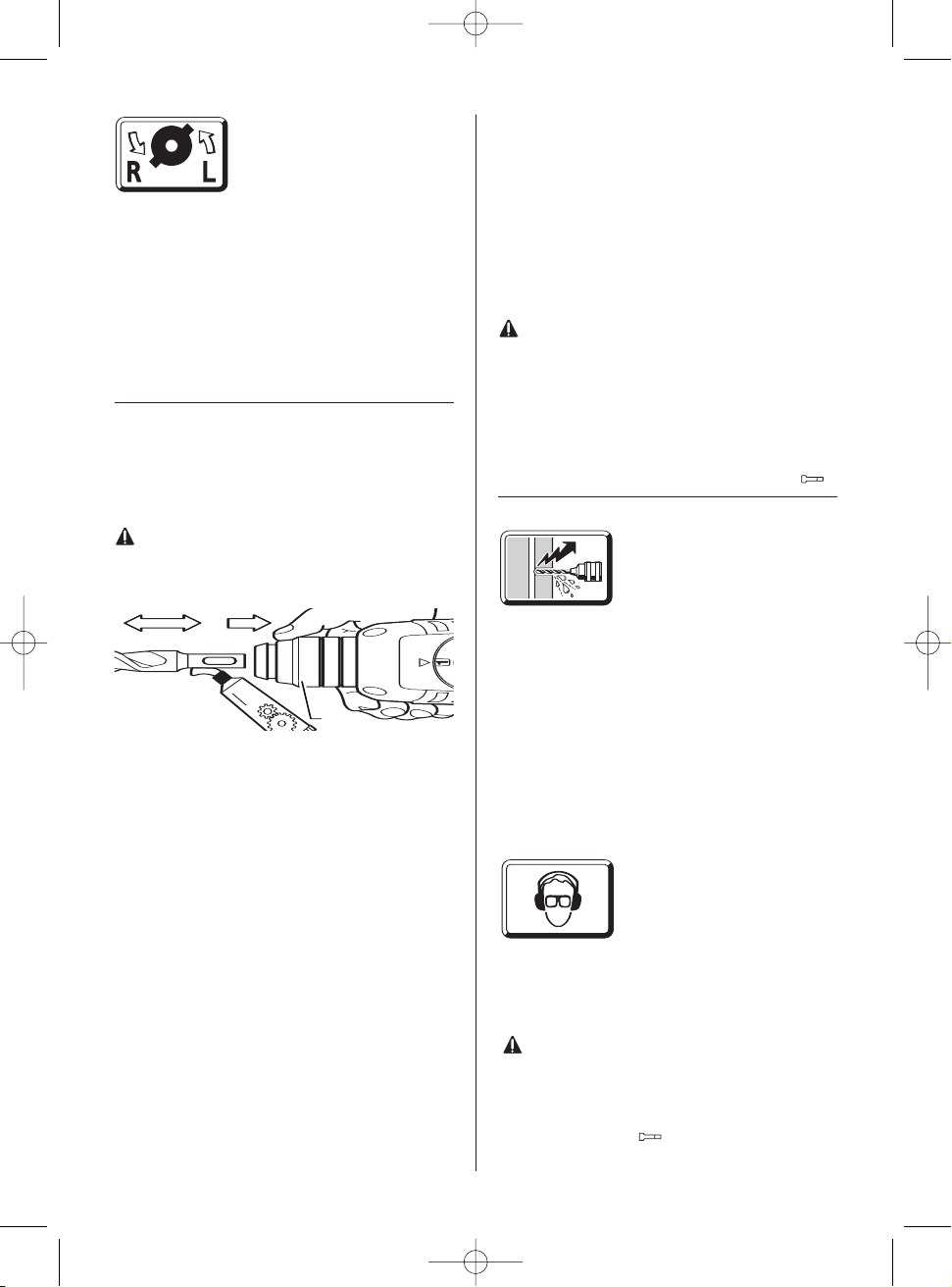
COMMUTATION DU SENS DE ROTATION
Le commutateur de sens de
rotation 6 ne doit être actionné
que lorsque la machine est à
l’arrêt complet!
Saisir le commutateur de sens
de rotation 6.
Rotation à droite: mettre le commutateur de
sens de rotation 6 sur la position « R ».
Rotation à gauche: mettre le commutateur de
sens de rotation 6 sur la position « L ».
Important! Appuyer chaque fois à fond le com-
mutateur de sens de rotation 6, c’est-à-dire veil-
ler à ce qu’il s’encliquette de façon perceptible.
Lorsque le commutateur de sens de rotation 6 a
été mis sur une position intermédiaire entre « R
»(rotation à droite) et « L »(rotation à gauche),
l’appareil ne se met pas en marche.
7. MISE EN PLACE / RETRAIT DE L’OUTIL
La fixation de l’outil 1 est conçue de manière à
recevoir et à bloquer les forets et autres burins
sans l’aide d’aucune clé.
MISE EN PLACE DE L’OUTIL
Toujours extraire la fiche du cordon d’alimen-
tation modulaire hors de la prise électrique
avant d’entreprendre une quelconque inter-
vention sur l’appareil lui-même.
Nettoyer puis graisser légèrement la queue de
l’outil.
Repousser la bague de verrouillage 3 vers l’arriè-
re. Introduire l’outil dans la fixation tout en impri-
mant à l’outil un mouvement de rotation selon
son axe principal, jusqu’à ce qu’il enclenche.
Relâcher la bague de verrouillage 3. Contrôler
enfin que l’outil est bien en place et parfaitement
maintenu.
Veiller à ne pas endommager le capuchon anti-
poussières 2.
Remplacer sans délai tout capuchon anti-
poussières détérioré!
RETRAIT DE L’OUTIL
Repousser la bague de verrouillage 3 vers l’arriè-
re. Extraire l’outil hors de la fixation.
MISE EN PLACE D’UN BURIN
Mettre le commutateur stop de rotation 4 dans
une position intermédiaire. Ceci fait, l’outil de
burinage se laisse tourner sans difficulté dans la
position de travail désirée.
Remettre ensuite le commutateur stop de rota-
tion 4 sur la position . Le burin s’encliquette
automatiquement dès qu’il est sollicité radiale-
ment par le processus de travail et de burinage.
8. MANDRIN (ACCESSOIRE)
Pour réaliser des travaux de perçage dans le
métal, le bois et les matières plastiques au
moyen d’un foret à queue cylindrique, l’utilisateur
peut faire appel à un mandrin (de 13 mm d’ouver-
ture maximale), livrable en tant qu’accessoire.
Ce mandrin se monte sur l’adaptateur (accessoi-
re) permettant d’utiliser le programme d’embouts
de tournevis. L’appareil est compatible avec n’im-
porte quel mandrin conventionnel doté d’un file-
tage intérieur 1/2" x 20 UNF (de 13 mm d’ouver-
ture maximale).
MONTAGE D’UN MANDRIN
Toujours extraire la fiche du cordon d’alimen-
tation modulaire hors de la prise électrique
avant d’entreprendre une quelconque inter-
vention sur l’appareil lui-même.
Nettoyer le filetage du mandrin (accessoire) ainsi
que celui de l’adaptateur 13 (accessoire).
Visser le mandrin sur l’adaptateur. Mettre l’adap-
tateur en position dans la fixation d’outil. Le ver-
rouiller comme s’il s’agissait d’un simple foret.
Pour bloquer le mandrin (30 Nm), mettre le com-
10
Fet
t
3
Fet
t
3
Fet
t
3
Fet
t
Fet
t
3
Fet
t
3
Fet
t
3
librettoBH252R 21-08-2007 9:30 Pagina 10

mutateur stop de rotation 4 sur la position
9. CONSEILS PRATIQUES
Ne pas percer de trous à tra-
vers des gaines électriques ou
des conduites d’eau ou de gaz
dissimulées. Avant de percer,
procéder toujours à un examen
de la paroi considérée. Si nécessaire, faire appel
àun détecteur de métal.
Pour percer dans les métaux, il convient de tou-
jours utiliser un foret parfaitement affûté et en
excellent état. Pour percer la pierre ou le béton,
utiliser des forets à mise au carbure.
Ajuster toujours la vitesse de rotation du foret au
matériau à travailler d’une part et au diamètre du
foret mis en oeuvre d’autre part. Pour travailler
de manière encore plus précise dans les métaux
ou dans le bois, faire appel à un support de pre-
çage (accessoire).
TRAVAUX DE PERFORA-
TION, DE BURINAGE
Porter des lunettes de sécu-
rité ainsi qu’une protection
acoustique.
Ne pas exercer de pression exagérée. Cela ne
contribue pas à améliorer les performances de la
machine.
Pendant les travaux de burinage, les meilleures
performances sont obtenues lorsque les morce-
aux de matériau abattus sont de petite taille.
Pendant les travaux de burinage, travailler
toujours avec une paire de lunette de sécuri-
té. La poignée supplémentaire 11 doit être
montée. Avant de mettre la machine en mar-
che, s’assurer que le commutateur stop de
rotation 4 est bien dans la position
PERÇAGE DANS DU CARRELAGE
Le perçage d’un carreau de faïence doit s’effec-
tuer à petite vitesse. N’activer le mécanisme de
frappe qu’après avoir complètement traversé le
carreau de faïence.
VISSAGE
L’adaptateur 13 (accessoire) permet d’utiliser les
embouts de tournevis. Il est compatible avec les
embouts de tournevis du commerce dotés d’une
queue six pans de 6,3 mm (1/4", DIN 3126, pro-
fil C).
Les embouts de tournevis sont maintenus dans
l’adaptateur par un ressort. Il convient donc de
ne travailler qu’avec des embouts dotés d’une
rainure latérale.
10. ACCOUPLEMENT À GLISSEMENT
Dès que l’outil de perçage se coince ou qu’il s’ac-
croche, l’accouplement à glissement se déclen-
che.
Décharger immédiatement la machine en tirant
l’outil de perçage vers l’arrière.
Maintenir toujours la machine des deux mains et
prendre une position stable et bien en équilibre.
11. INTERVENTIONS DE MAINTENANCE
Toujours extraire la fiche du cordon d’alimen-
tation modulaire hors de la prise électrique
avant d’entreprendre une quelconque inter-
vention sur l’appareil lui-même.
Les ouïes de refroidissement de la machine doi-
vent rester propres.
Essuyer régulièrement les pièces en matière pla-
stique accessibles de l’extérieur avec un chiffon
humide mais non imbibé de produit de nettoyage.
Après avoir exploité la machine de manière
intensive pendant une longue période, la confier
àun centre de service agréé Rupes af in qu’elle
soit inspectée sérieusement et complètement
nettoyée.
12. PROTECTION DE L’ENVIRONNEMENT
Ne pas jeter les appareils
électriques dans les ordures
ménagères !
Récupération des matières
premières plutôt qu'élimina-
tion des déchets
Les appareils, comme d'ailleurs leurs accessoi-
res et emballages, doivent pouvoir suivre chacun
une voie de recyclage appropriée.
Ce manuel d'instructions a été fabriqué à partir
d'un papier recyclé blanchi sans chlore.
Nos pièces plastiques ont été marquées en vue
d'un recyclage sélectif des différents matériaux.
11
Fet
t
3
Fet
t
3
Fet
t
3
Fet
t
3
Fet
t
3
Fet
t
3
Fet
t
3
librettoBH252R 21-08-2007 9:30 Pagina 11

PNEUMATIK-BOHRHAMMER BH252R
(SIEHE ABB. SEITE 25-26)
Verwendung
Der Pneumatik-Bohrhammer ist universell ein-
setzbar zum Hammerbohren, für leichte
Meilbelarbeiten in Gestein und zum Bohren
sowie Schrauben in Holz, Metall und Kunststoff.
1. SICHERHEITSHINWEISE
UND UNFALLSCHUTZ
Bevor Sie die Maschine in Betrieb nehmen, lesen
Sie die Bedienungsanleitung vollständig durch,
befolgen Sie die Sicherheitshinweise in dieser
Anleitung sowie die Allgemeinen
Sicherheitshinweise für Elektrowerk¬zeuge im
beigelegten Heft.
Wird das Netzkabel während der Arbeit
beschädigt, sofort Netzstecker ziehen.
Niemals mit beschädigtem Netzkabel arbei-
ten.
Schutzbrille, Gehörschutz, Schutzhandschuhe
und festes Schuhwerk tragen.
Tragen Sie Gehörschutz. Die Einwirkung
von Lärm kann Gehörverlust bewirken.
Benutzen Sie die mit dem Gerät geliefer-
ten Zusatzhandgriffe. Der Verlust der
Kontrolle kann zu Verletzungen führen.
Kein asbesthaltiges Material bearbeiten.
Gerät nicht am Kabel tragen.
Steckdosen im Aul3enbereich müssen über
Fehler-stromschutzschalter (FI-) abgesichert
sein.
Um die Maschine zu kennzeichnen, darf das
Gehäuse nicht angebohrt werden. Die
Schutzisolation wird überbrückt. Verwenden
Sie Klebeschilder.
Wenn der Bohrer unerwartet festklemmt,
reagiert die Maschine ruckartig. Nehmen Sie
deshalb immer einen sicheren Stand ein und
halten Sie die Maschine fest mit beiden
Händen.
2. BILD
1Werkzeugaufnahme
2Staubschutzkappe
3Entriegelungshülse
4Drehstoppschalter
5Lüftungsschlitze
6Drehrichtungsumschalter
7Feststellknopf für Ein-/Ausschalter
8Ein-/Ausschalter/Drehzahlsteuerung
9Umschalter Bohren/Hammerbohren
10 Aufnahme für Tiefenanschlag
11 Zusatzgriff
12 Arretierung Netzkabelmodul
13 Adapter für Schraub-Bits/Bohrfutter
Abgebildetes oder beschriebenes Zubehòr
muss nicht zum Lieferumfang gehòren.
3. TECHNISCHE DA TEN
Aufnahmeleistung 700 Watt
Drehzahlsteuerung 0-1170 1/min
Leerlaufschlagzahl max 5270 1/min
Schlagenergie 2,5 Joule
Empfohlener Bohrbereich
Hammerbohren Ø 4-16 mm
Hammerbohren in Beton Ø 24 mm
Stahl Ø13 mm
Leichtmetall Ø 30 mm
Spannhals Ø 43 mm
Gewicht 2,6 Kg
4. LARM-/VIBRATIONSINFORMATION
Messwerte ermittelt entsprechend EN 60 745.
Der A-bewertete Geräuschpegel des Geräts
beträgt typischerweise: Schalldruckpegel 88 dB
(A); Schallleistungspegel 99dB (A).
Messunsicherheit K= 3 dB
Gehörschutz tragen!
Die bewertete Beschleunigung beträgt typischer-
weise 7,6 m/s2.
5. ZUSATZGRIFF UND NETZKABELMODUL
MONTIEREN
Ziehen Sie vor allen Arbeiten am Gerät den
Netzstecker.
Betreiben Sie das Gerät nur mit dem Zusatzgriff
11. Den Zusatzgriff auf den Spannhals setzen
und mit der Spannschraube festziehen.
Schliel3en Sie das Netzkabelmodul an den
Handgriffan. Der Stecker muss einrasten.
Verwenden Sie das Netzkabelmodul nur für
RupesElektrowerkzeuge. Versuchen Sie
nicht, andere Geräte damit zu betreiben.
Verwenden Sie nur Original Rupes-
Netzkabelmodule und zwar mindestens schwere
Gummischlauchleitung.
6. INBETRIEBNAHME
Prüfen Sie vor Inbetriebnahme, ob die
Netzspannung mit der Angabe auf dem
Typenschild des Gerätes übereinstimmt.
EIN-/AUSSCHALTEN
Den Ein-/Ausschalter 8 drücken bzw. wieder
loslassen.
Der Ein-/Ausschalter kann mit dem
Feststellknopf 7 arretiert werden. Zum Lösen den
12
Deutsch
Fet
t
3
Fet
t
3
Fet
t
3
Fet
t
3
Fet
t
3
Fet
t
3
Fet
t
3
Fet
t
3
Fet
t
3
Fet
t
3
Fet
t
3
Fet
t
3
librettoBH252R 21-08-2007 9:30 Pagina 12

Ein-/Ausschalter 8 kurz drücken und loslassen.
DREHSTOPP
Mit dem Drehstoppschalter 4 können Sie zwei
Einstellungen wählen.
1=Bohren/Hammerbohren, Rührarbeiten
=Keine Drehbewegung: Leichte Meil3elar-
beiten.
Die Umschaltung lälßt sich am besten im
Stillstand vornehmen.
Nach Betätigung des Ein-/Ausschalters 8 bzw.
beim Anlaufen der Maschine schaltet das
Getriebe in die vorgewählte Einstellung.
BOHREN - HAMMERBOHREN
Zum Bohren den Umschalter 9 auf stellen.
Zum Hammerbohren auf stellen.
Die Umschaltung lässt sich am besten im
Stillstand vornehmen. Nach Betätigung des Ein-
/Ausschalters 8 bzw. beim Anlaufen der
Maschine schaltet das Getriebe in die vorgewä-
hlte Einstellung.
Hinweise: Linkslauf beim Hammerbohren
beschädigt den Bohrer. Bei Arbeiten mit
Diamant-Bohrkronen und bei Rührarbeiten das
Schlagwerk ausschalten.
Für Meil3elarbeiten den Umschalter 4 auf
stellen.
Verwenden Sie beim Hammerbohren aus-
schließlich hartmetallbestückte Bohrer mit
SDS plusSchaft. Die Verwendung handelsübli-
cher Steinbohrer mit zylindrischem Schaft unter
Verwendung des Adapters 13 und eines üblichen
Bohrfutters unter Einsatz des pneumatischen
Hammerwerkes ist nicht möglich.
DREHZAHLSTEUERUNG
Mit dem Ein-/Ausschalter 8
können Sie die Drehzahl stu-
fenlos steuern. Bei leichtem
Druck auf den Ein-/Ausschalter
8beginnt die Maschine lan-
gsam zu drehen; mit zunehmenden Druck erhöht
sich die Drehzahl.
DREHRICHTUNG UMSCHALTEN
Betätigen Sie den
Drehrichtungsumschalter 6 nur
im Stillstand!
Greifen Sie den
Drehrichtungsumschalter 6
beidseitig.
Rechtslauf: Drehrichtungsumschalter 6 auf “R“
stellen.
Linkslauf: Drehrichtungsumschalter 6 auf “L“
stellen.
Wichtig! Drehrichtungsumschalter 6 jeweils bis
zum Anschlag am Gehäuse durchdrücken, d. h.
bis er spürbar einrastet.
Steht der Drehrichtungsumschalter 6 zwischen
Pos. “R“ und “L“, kann die Maschine nicht einge-
schaltet werden.
7. WERKZEUG EINSETZEN/ENTNEHMEN
Die Werkzeugaufnahme 1 spannt Bohr- und
Meilßelwerkzeuge ohne Werkzeugschlüssel.
WERKZEUG EINSETZEN
Ziehen Sie vor allen Arbeiten am Gerät den
Netzstecker.
Reinigen Sie den Werkzeugschaft und fetten Sie
ihn leicht.
Ziehen Sie die Entriegelungshülse 3 zurück.
Führen Sie das Werkzeug drehend in die
Werkzeugaufnahme ein, bis es einrastet. Lassen
Sie die Entriegelungshülse los. Prüfen Sie das
Werkzeug auf festen Sitz.
Achten Sie darauf, dass die Staubschutzkappe 2
nicht beschädigt wird.
Beschädigte Staubschutzkappe unbedingt
ersetzen!
WERKZEUG ENTNEHMEN
Schieben Sie die Entriegelungshùlse 3 nach hin-
ten und ziehen Sie das Werkzeug heraus.
MEISSEL EINSTELLEN
Bringen Sie den Drehstoppschalter 4 in eine
Zwischenstellung. Der Meilßel làsst sich jetzt von
Hand in die erforderliche Arbeitsposition drehen.
Stellen Sie danach den Drehstoppschalter 4 wie-
der auf Position. Der Meilßel rastet automatisch
ein, sobald er durch den Arbeits- bzw.
Meilßelvorgang radial belastet wird.
8. BOHRFUTTER (ZUBEHÒR)
Fùr Bohrarbeiten in Metall, Holz und Kunststoff
mit Bohrern mit normalem Schaft, ist ein
Bohrfutter (max.13 mm Spannweite) lieferbar.
Das Bohrfutter wird auf den Adapter (Zubehòr)
fùr Schraub-Bits montiert. Es kònnen alle ùbli-
chen Bohrfutter mit Innengewinde 1/2" x 20 UNF
(Spannweite max.13 mm) verwendet werden.
13
Fet
t
3
Fet
t
3
Fet
t
3
Fet
t
3
Fet
t
3
Fet
t
3
librettoBH252R 21-08-2007 9:30 Pagina 13

BOHRFUTTER MONTIEREN
Ziehen Sie vor allen Arbeiten am Geràt den
Netzstecker.
Gewinde am Bohrfutter (Zubehòr) und am
Adapter 13 (Zubehòr) reinigen.
Schrauben Sie das Bohrfutter auf den Adapter
und verriegeln Sie den Adapter wie einen Bohrer
in der Werkzeugaufnahme. Um das Bohrfutter
festzuziehen (30 Nm), stellen Sie den
Drehstoppschalter 4 vorùbergehend auf Position
.
9 FURDIE PRAXIS
Bohren Sie nicht in verdeckt
liegende elektrische Leitungen,
Gas- und Wasserrohre.
Untersuchen Sie vorher die zu
bearbeitenden Flàchen; zum
Beispiel mit einem Metallortungsgeràt.
Verwenden Sie fùr Metall nur einwandfrei
geschàrfte Bohrer, fùr Stein und Beton nur har-
tmetallbestùckte Gesteinsbohrer.
Passen Sie die Drehzahl immer dem zu bearbei-
tenden Werkstoff und dem Bohrerdurchmesser
an. Fùr genaues Arbeiten in Metall und Holz die
Maschine in einen Bohrstànder (Zubehòr) set-
zen.
HAMMERBOHREN -
MEISSELN
Schutzbrille und Gehòrschutz
tragen.
Ùben Sie keinen zu starken
Anpressdruck aus; die Leistung wird dadurch
nicht erhòht.
Beim Meilßeln wird die beste Wirkung erzielt,
wenn nur kleinere Materialstùcke herausgebro-
chen werden.
Beim Meilßeln nur mit Schutzbrille und
Zusatzgriff 11arbeiten. Prùfen Sie vor der
Inbetriebnahme, ob der Drehstoppschalter 4
in Stellung eingerastet ist.
IN FLIESEN BOHREN
Eine Fliese langsam anbohren. Erst wenn die
Fliese durchbohrt ist, auf Hammerbohren umstel-
len.
SCHRAUBEN
Der Adapter 13 (Zubehòr) kann Schraub-Bits auf-
nehen. Es kònnen handelsùbliche Bits eingesetzt
werden mit dem Sechskantmalß 6,3 mm bzw.
1/4" (DIN 3126, Form C).
Schraub-Bits werden im Adapter durch einen
Federring gehalten. Deswegen nur Bits mit
Kerben einsetzen.
10. RUTSCHKUPPLUNG
Klemmt oder hakt das Bohrwerkzeug, lòst die
Rutschkupplung aus.
Entlasten Sie sofort die Maschine, indem Sie das
Bohrwerkzeug zurùckziehen.
Halten Sie die Maschine immer fest mit beiden
Hànden und nehmen Sie einen sicheren Stand
ein.
11. WARTUNGSMAßNAHMEN
Ziehen Sie vor allen Arbeiten am Geràt den
Netzstecker.
Halten Sie die Lùftungsschlitze stets sauber.
Von aulßen zugàngliche Kunststoffteile regelmàl-
ßig mit einem Tuch ohne Reinigungsmittel abwi-
schen.
Nach starker Beanspruchung ùber einen lànge-
ren Zeitraum sollte das Geràt zur Inspektion und
grùndlichen Reinigung einer Rupes-Servicestelle
zugefùhrt.
12. UMWELTSCHUTZ
Werfen sie Elektrowerkzeuge
nicht in den Hausmull.
Rohstoffrückgewinnung
statt Müllentsorgung.
Gerat, Zubehor und
Verpackung sollten einer umweltgerechten
Wiederverwertung zugefuhrt werden.
Diese Anleitung ist aus chlorfrei gefertigtem
Recycling-Papier hergestellt.
Zum sortenreinen Recycling sind Kunststoffteile
gekennzeichnet.
14
Fet
t
3
Fet
t
3
Fet
t
3
Fet
t
3
Fet
t
3
Fet
t
3
Fet
t
3
librettoBH252R 21-08-2007 9:30 Pagina 14

MARTILLO PERFORADOR CONPERCUTOR
NEUMÁTICO BH252R
(VER IMAGENES PAG. 25-26)
Aplicaciòn
El martillo perforador conpercutor neumático es
de aplicaciòn universal para taladrar con percu-
tor, para trabajos leves de cincelado en piedra,
asl como para taladrar y atornillar en madera,
metal y material sintético.
1. INDICACIONES DE SEGURIDAD Y PRE-
VENCIÒN DE ACCIDENTES
Antes de poner la máquina en funcionamiento
lea lntegramente las instrucciones de manejo y
aténgase a las indicaciones de seguridad alll
descritas asl como a las indicaciones generales
de seguridad para herramientas eléctricas en el
folleto adjunto.
Si se llegase a deteriorar el cable de red
durante su utilizaciòn extraer inmediatamente
el enchufe de la red.
No trabaje jamás con cable de red deteriora-
do.
Colocarse unas gafas de protecciòn, un pro-
tector de oldos, unos guantes de protecciòn y
llevar un calzado fuerte.
Utilice unos protectores auditivos. El ruido
intenso puede provocar sordera.
Emplee los puños adicionales suministra-
dos con el aparato. La pérdida de control
sobre el aparato puede provocar un acciden-
te.
No trabajar materiales que contengan amian-
to.
No transportar el aparato asiéndolo del
cable.
Las tomas de corriente en el exterior deben
protegerse por un fusible diferencial.
Para identificar la máquina no debe taladrar-
se la carcasa, puesto que se inutilizarla el
aislamiento de protecciòn. Use etiquetas
adhesivas.
En caso de agarrotarse la broca repentina-
mente, la máquina reacciona bruscamente.
Por ello tome siempre una posiciòn estable
sujetando la máquina firmemente con ambas
manos
2. FIGURA
1Portaùtiles
2Caperuza antipolvo
3Casquillo de desenclavamiento
4Mando desactivador de giro
5Aberturas de refrigeraciòn
6Selector de sentido de giro
7Botòn de enclavamiento para interruptor de
conexiòn/desconexiòn
8Interruptor de conexiòn/desconexiòn/Control
de as revoluciones
9Conmutador taladrar/taladrar con percutor
10 Alojamiento para tope de profundidad
11 Empuiadura adicional
12 Fiador de mòdulo de cable de red
13 Adaptador para láminas de
desatornillador/portabrocas
Los accesorios ilustrados o descritos no
siempre corresponden al volumen de sumini-
stro.
3. DA TOS TÉCNICOS
Potencia absorbida 700 Watt
Velocidad en vaclo 0-1170 1/min
Nº de percusiones en vaclo max 5270 1/min
Energla de impacto 2,5 Joule
Margen recomendado para taladrar con
percutor en hormigòn Ø 4-16 mm
Taladrar con percutor en hormigòn Ø 24 mm
Acero Ø13 mm
Aleaciòn ligeral Ø 30 mm
Cuello de fijaciòn Ø43 mm
Peso 2,6 Kg
4. INFORMACIÒN SOBRE RUIDOS Y VIBRA-
CIONES
Determinación de los valores de medición según
norma EN 60 745.
El nivel de ruido del aparato, en condiciones nor-
males, determinado con un filtro A, es de: nivel
de presión de sonido 88 dB (A); nivel de poten-
cia acústica 99 dB (A).
Inseguridad de la medición K = 3 dB.
¡Se recomiendan protectores auditivos!
El nivel de vibraciones típico es de 7,6 m/s2.
5. MONTAJE DE LA EMPURIADURA ADICIO-
NAL Y DEL MÒDULO DE CABLE DE RED
¡Antes de cualquier manipulaciòn en el apa-
rato extraer el enchufe de la red!
Utilice el aparato solamente junto con la empuia-
dura adicional 11. Introducir la empuiadura adi-
cional sobre el cuello de fijaciòn y apretarla con
el tornillo de sujeciòn.
Conecte el mòdulo de cable de red a la empuia-
dura. El conector debe quedar enclavado.
Emplee el mòdulo de cable de red sòlo en
herramientas eléctricas Rupes. No intente
accionar otros aparatos con él.
Utilice solamente mòdulos de cable de red origi-
15
Español
Fet
t
3
Fet
t
3
Fet
t
3
Fet
t
3
Fet
t
3
Fet
t
3
Fet
t
3
Fet
t
3
Fet
t
3
Fet
t
3
Fet
t
3
librettoBH252R 21-08-2007 9:30 Pagina 15

nales Rupes, como minimo, con recubrimiento
de caucho para trato rudo.
6. PUESTA EN MARCHA
Compruebe antes de la puesta en marcha, si
la tensiòn de red coincide con la indicada en
la placa de caracteristicas del aparato.
CONEXION/DESCONEXION
Presionar o soltar el interruptor de
conexiòn/desconexiòn 8.
El interruptor de conexiòn/desconexiòn puede
enclavarse con el botòn de enclavamiento 7.
Para liberar el interruptor de conexiòn/descone-
xiòn 8 presionarlo brevemente y soltarlo.
DETENCIÒN DE GIRO
Con el mando desactivador de giro 4 pueden
seleccionarse dos modalidades.
1 = Taladrar con y sin percutor, agitar
=Sin rotaciòn: para trabajos leves de cince-
lado.
La conmutaciòn se realiza preferentemente con
la máquina detenida.
Después de accionar el interruptor de
conexiòn/desconexiòn 8, o bien con la puesta en
marcha de la máquina, el engranaje se conmuta
alaposiciòn preseleccionada.
TALADRAR - TALADRAR CON PERCUTOR
Para taladrar colocar el conmutador 9 sobre
Para taladrar con percutor llevarlo a
La conmutaciòn se realiza preferentemente con
la máquina detenida. Después de accionar el
interruptor de conexiòn/desconexiòn 8, o bien
con la puesta en marcha de la máquina, el
engranaje se conmuta a la posiciòn preseleccio-
nada.
Indicaciones: Al taladrar con percutor con giro a
izquierdas se daia la broca. Desconectar el
mecanismo percutor al emplear coronas diaman-
tadas o un dispositivo mezclador.
Para realizar trabajos de cincelado colocar el
conmutador 4 en
Al taladrar con percusiòn utilice exclusiva-
mente brocas de metal duro con véstago
SDS-plus. El mecanismo percutor neumático, no
debe emplearse con brocas para piedra de
vástago cilindrico usuales en el comercio que
han sido fijadas a un portabrocas comùn emple-
ando el adaptador 13.
CONTROL DE REVOLUCIO-
NES
Con el interruptor de cone-
xiòn/desconexiòn 8 pueden
ajustarse las revoluciones de forma continua. Un
presiòn leve del interruptor de conexiòn/desco-
nexiòn 8 hace girar la máquina con bajas revolu-
ciones; éstas van aumentando a medida que se
incrementa la presiòn.
INVERSION DEL SENTIDO DE GIRO
¡Accione el selector de sentido
de giro 6 sòlo con la máquina
parada!
Sujete el selector de sentido de
giro 6 por ambos lados.
Giro a derechas: colocar el selector de sentido
de giro 6 en “R”.
Giro a izquierdas: colocar el selector de sentido
de giro 6 en “L”.
¡Atenciòn! Presionar el selector de sentido de
giro 6 hasta hacer tope en la carcasa, de mane-
ra que enclave perceptiblemente.
De encontrarse el selector de sentido de giro 6
entre las posiciones “R” y “L”, no puede conectar-
se la máquina.
7. INSERCIÒN/EXTRACCIÒN DEL ÙTIL
El portaùtiles 1 sujeta brocas y cinceles sin
requerir de una llave para ùtiles.
INSERCION DEL UTIL
¡Antes de cualquier manipulaciòn en el aparato
extraer el enchufe de la red!
Limpiar y engrasar ligeramente el vástago del
ùtil.
Retire hacia atrás el casquillo de desenclava-
miento 3. Introduzca girando el ùtil en el portaù-
tiles hasta que engatille. Suelte el casquillo de
enclavamiento. Compruebe la fijaciòn correcta
del ùtil.
Ponga cuidado de no daiar la caperuza antipolvo
2.
¡Sustituir imprescindiblemente una caperuza
antipolvo deteriorada!
EXTRACCION DEL UTIL
Empuje hacia atras el casquillo de desenclava-
miento 3 y extraiga el ùtil.
16
Fet
t
3
Fet
t
3
Fet
t
3
Fet
t
3
Fet
t
3
Fet
t
3
Fet
t
3
Fet
t
3
librettoBH252R 21-08-2007 9:30 Pagina 16

AJUSTE DEL CINCEL
Coloque el mando desactivador de giro 4 en una
posiciòn intermedia. El cincel deja girarse ahora
amano a la posiciòn de trabajo requerida.
Lleve a continuaciòn el mando desactivador de
giro 4 nuevamente a la posiciòn . El cincel
se enclava automaticamente al solicitarse radial-
mente durante el trabajo.
8. PORTABROCAS (ACCESORIO)
Para taladrar en metal, madera y material sintéti-
co con brocas de vastago normales puede adqui-
rirse un portabrocas (capacidad de apertura 13
mm max.). El portabrocas se monta sobre un
adaptador (accesorio) para laminas de desator-
nillador.Pueden emplearse todos los portabro-
cas normales con rosca interior 1/2" x 20 UNF
(capacidad de apertura 13 mm max.).
MONTAJE DEL PORTABROCAS
¡Antes de cualquier manipulaciòn en el apa-
rato extraer el enchufe de la red!
Limpiar la rosca del portabrocas (accesorio) y del
adaptador 13 (accesorio).
Enrosque el portabrocas sobre el adaptador y
engatille el adaptador en el portaùtiles igual que
una broca. Para apretar el portabrocas (30 Nm),
colocar el mando desactivador de giro 4 transito-
riamente en la posiciòn .
9. CONSEJOS PRÀCTICOS
No taladrar conductores eléc-
tricos, tuberlas de gas o de
agua que pudieran encontrarse
ocultos. Compruebe las areas
previamente; por ejemplo con
un detector de metales.
Utilice en metal ùnicamente brocas con buen filo
yen piedra y hormigòn sòlo brocas para piedra
con filos de metal duro.
Adapte siempre las revoluciones al material a
trabajar y al diametro de la broca. Para trabajar
con precisiòn metal y madera fijar la maquina en
un soporte para taladrar (accesorio).
TALADRAR CON PERCUTOR
-CINCELAR
Colocarse gafas de protec-
ciòn y un protector de oidos.
No ejercer una presiòn de apli-
caciòn excesiva. Ello no incrementa el rendi-
miento.
Al cincelar se obtiene una mayor eficacia al
arrancar material en trozos pequeios.
Al cincelar, trabajar solamente con gafas de pro-
tecciòn y la empuiadura adicional 11.
Compruebe antes de la puesta en marcha si el
mando desactivador de giro 4 se encuentra
enclavado en la posiciòn .
COMO TALADRAR AZULEJOS
Taladrar un azulejo lentamente. Solamente tras
haber traspasado el azulejo cambiar a taladrar
con percutor.
ATORNILLAR
El adaptador 13 (accesorio) permite alojar lami-
nas de desatornillador. Pueden emplearse lami-
nas (bits) usuales en el comercio con un hexago-
no de 6,3 mm o bien 1/4" (DIN 3126, forma C).
Las laminas de desatornillador se mantienen
sujetas en el adaptador por una arandela muelle.
Utilizar por ello ùnicamente laminas con mue-
scas.
10. ACOPLAMIENTO DE DESLIZAMIENTO
En caso de agarrotarse o atascarse el ùtil de per-
forar se activa el acoplamiento de deslizamiento.
Descargar inmediatamente la maquina extrayen-
do el ùtil de perforar.
Sujetar siempre la maquina con ambas manos y
manteniendo una posiciòn estable.
11. MEDIDAS PARA MANTENIMIENTO
¡Antes de cualquier manipulaciòn en el apa-
rato extraer el enchufe de la red!
Mantenga siempre limpias las aberturas de refri-
geraciòn.
Limpiar periòdicamente con un paio, sin emplear
productos de limpieza, las piezas de material sin-
tético accesibles desde el exterior.
Después de una fuerte solicitaciòn durante un
tiempo prolongado debe entregarse el aparato
para su inspecciòn y limpieza a fondo a un taller
de servicio Rupes.
12. PROTECCIÒN DEL MEDIO AMBIENTE
¡No deseche los aparatos
eléctricos junto con los resi-
duos domésticos!
Recuperación de materias
primas en lugar de producir
desperdicios
El aparato, los accesorios y el embalaje debieran
someterse a un proceso de recuperación que
respete el medio ambiente.
Estas instrucciones se han impreso sobre papel
reciclado sin la utilizazión de cloro.
Para efectuar un reciclaje selectivo se han iden-
tificado las piezas de plástico.
17
Fet
t
3
Fet
t
3
Fet
t
3
Fet
t
3
Fet
t
3
librettoBH252R 21-08-2007 9:30 Pagina 17

Электропневмоперфоратор BH252R
(см.рисунки на страницах 25-26)
азначение
Электропневмоперфоратор предназначен для
сверления отверстий с ударным действием (пер-
форирования), для выполнения легких работ в режиме
долбления камня, горных пород, бетона, кирпича, а
также для сверления и завинчивания шурупов в
древесину, металл и пластмассу.
1. АА ОАО
ОООО
режде чем ввести инструмент в эксплуатацию,
следует прочесть до конца инструкции по
эксплуатации, соблюдать указания по технике
безопасности, содержащиеся в настоящих
инструкциях, а также общие правила безопасности для
электрического оборудования, приведенные в
прилагаемой брошюре.
случае, если во время работы будет поврежден
сетевой кабель, следует незамедлительно
извлечь вилку из электрической розетки.
и в коем случае не следует работать с
поврежденным кабелем.
ледует носить очки, защитные наушники и
перчатки, а также защитную обувь.
ледует использовать акустическую защиту.
оздействие шума может вызвать потерю слуха.
ледует использовать дополнительные ручки,
поставляемые в комплекте с инструментом.
отеря контроля над инструментом может
привести к возникновению аварий.
е следует обрабатывать материал, содержащий
асбест.
е следует перемещать инструмент, потянув его
за кабель.
озетки, используемые вне помещений, должны
быть предохранены посредством
предохранительного выключателя для токов
повреждения (FI).
е допускается пробивание отверстий в корпусе
инструмента для того, чтобы пометить его.
ащитная изоляция соединяется с помощью
перемычки.
ледует использовать самоконтролирующиеся
таблички.
сли сверло неожиданно останавливается,
инструмент реагирует посредством отдачи.
оэтому следует всегда поддерживать
безопасную дистанцию и хорошо держать
инструмент в руках.
2.Общий вид перфоратора (см. рис.)
1. нездо патрона для зажима инструмента
2. ылезащитный колпак (пыльник)
3. тулка разблокировки
4. ереключатель блокировки вращения (при работе с
зубилом или долото)
5. ентиляционные отверстия
6. ереключатель направления вращения
7. нопка фиксации положения выключателя для
длительного и непрерывного режима работы
8. ыключатель с электронным управлением числа
оборотов
9. ереключатель режима простого сверления /
сверления с ударным действием
10. иксатор ограничителя глубины сверления
(линейки-упора)
11. ополнительная рукоятка
12. иксатор модуля сетевого кабеля
13. Адаптер для бита (наконечника винтоверта) /
навинчивания сверлильного патрона
оказанные на рисунке или дающиеся в описании
детали и принадлежности не всегда входят в объем
поставки.
3. ехнические данные
ходная, потребляемая мощность 700 т
холостого хода 0-1100 об/мин.
исло ударов в режиме
холостого хода макс. 5896 уд/мин.
Энергия удара 2,5 ж
с ударным действием полнотелыми
сверлами 4-16 мм
сверлении бетона с ударным действием 24 мм
сверлении стали 13 мм
сверлении древесины 30 мм
иаметр зажимной вро-шейки 43 мм
ес 2,6 кг
4. нформация о шумовой эмиссии/вибрации
змеренные значения получены в соответствии с
нормативом EN 60 745.
Уровень шумового давления: 90,5 dB (А)
Уровень мощности шума: 93,7 dB (А)
Уровень шумовой эмиссии на рабочем месте: 87,9
dB (A).
5. Установка дополнительной рукоятки и модуля
сетевого кабеля
еред началом проведения любых работ
отсоедините сетевой штекер от перфоратора.
ользуйтесь перфоратором всегда только с
установленной дополнительной рукояткой 11. ля
установки дополнительной рукоятки на зажимную
шейку перфоратора сначала ослабьте её захват,
вращая нижнюю часть рукоятки против часовой
стрелки. Установите рукояткуна зажимную шейку
18
У
Fet
t
Fet
t
3
Fet
t
3
Fet
t
3
Fet
t
3
Fet
t
3
Fet
t
3
Fet
t
3
Fet
t
3
F
Fet
t
3
librettoBH252R 21-08-2007 9:30 Pagina 18

перфоратора, поверните ее в нужную рабочую
позицию и хорошо затяните, вращая её нижнюю часть
по часовой стрелке. ставьте в специальное отверстие
ограничитель глубины сверления (линейку-упор) и
закрепите его с помощью фиксатора. одсоедините
модуль сетевого кабеля к основной рукоятке, штекер
при этом должен защелкнуться.
одсоедините модуль сетевого кабеля к основной
рукоятке, штекер при этом должен защелкнуться.
6. Эксплуатация перфоратора
еред началом работы убедитесь в том, что
напряжение ашей сети соответствует данным
напряжения, указанным в заводской табличке на
корпусе перфоратора.
ключение и отключение перфоратора
ерфоратор включается при нажатии кнопки
выключателя 8, размещенной в рукоятке. ля
отключения перфоратора отпустите кнопку
выключателя 7. помощью кнопки фиксации
положения выключателя для длительного и
непрерывного режима работы 7, находящейся на
боковой стороне рукоятки, можно зафикси-ровать
(застопорить) кнопку выключателя 8. ля снятия
выключателя с фиксации (чтобы выйти из режима
длительной и непрерывной работы) необходимо
повторно коротко нажать на кнопку выключателя 8 и
затем отпустить ее. нопка фиксации положения
выключателя автомати-чески возвращается в свое
исходное положение.
локировка вращения
ереключатель блокировки вращения (долбеж-ные
работы) 4 позволяет выбрать два различ-ных
положения настройки.
1 = сверление / сверление отверстий с ударным
действием (перфорирование), режим переме-шивания.
=вращение отсутствует: легкие долбежные
работы при помощи долото.
ыполнять переключение лучше всего после
остановки работы перфоратора.
осле того, как будет задействован выключатель 8 или
запущен в работу перфоратор, редуктор
переключается в предва-рительно выбранное
положение настройки. сли шестерня не будет входить
взацепление, проверните патрон рукой.
ереключение режима сверления – сверле-ния с
ударным действием (перфорирование)
ля режима сверления установите переклю-чатель 9 в
режим.
ля режима сверления с ударным действием
установите переключатель в режим.
ыполнять переключение лучше всего после
остановки работы перфоратора. осле того, как будет
задействован выключатель 8 или запущен в работу
перфоратор, редуктор переключается в
предварительно выбранное положение настройки.
Указание:евое вращение при сверлении в режиме
перфорирования является причиной повреждения
сверла или бура. ри работе с алмазными
сверлильными коронками и в режиме перемешивания
необходимо отключать ударный механизм. ри
выполнении долбежных работ при помощи долото
установите переключатель 4 в положение.
ри сверлении отверстий в режиме
перфорирования пользуйтесь исключи-тельно
сверлами SDS plus с твердо-сплавными напайками.
рименение стандартных сверл или буров по камню с
цилиндрическим хвостовиком при использовании
адаптера 13 и обычного сверлильного патрона при
включении пневматического механизма
перфорирования не допускается!
егулирование числа оборотов
помощью выключателя 8 можно
плавно регулировать число
оборотов. ри легком нажатии на
выключатель 8 перфоратор
начинает медленно вращаться, с
увеличением силы нажатия увеличивается и число
оборотов.
зменение направления вращения
ереключателем направления
вращения 6 можно манипулиро-
вать только после полной останов-
ки работы перфоратора!
ля переключения берите
переключатель 6 с двухсторон большим и
указательным пальцами.
равое вращение: установить переключатель
направления вращения 6 в положение «R».
евое вращение:установить переключатель
направления вращения 6 в положение «L».
ажно! еред включением перфоратора
переключатель направления враще-ния 6 необходимо
повернуть до упора на корпусе, т.е. до ощутимого
фиксируемого щелчка.
сли переключатель направления вращения 6 будет
находится в промежуточном положении между «R» и
19
Fet
t
3
Fet
t
3
Fet
t
3
Fet
t
Fet
t
3
librettoBH252R 21-08-2007 9:30 Pagina 19

«L», то включение перфоратора невозможно.
7. Установка и выемка инструмента
нездо патрона 1 предназначено для зажима в нем
таких инструментов, как сверло, бур или долото,
имеющих хвостовик “SDS plus”, без применения
специального ключа.
Установка инструмента
еред началом проведения любых работ
отсоедините сетевой штекер от перфоратора.
ля установки инструмента необходимо очистить
хвостовик инструмента и смазать его слегка
констистентной смазкой.
Оттяните назад втулкуразблокировки 3. ращая,
введите инструмент в гнездо патрона до упора, пока он
не защелкнется. Отпустите втулку разблокировки.
роверьте инструмент на прочность посадки. ледите
за тем, чтобы пылезащитный колпак 2 не был
поврежден.
случае повреждения пылезащитного колпака его
необходимо обязательно заменить!
ыемка инструмента
Отведите втулкуразблокировки 3 назад и выньте
инструмент.
Установка долото (зубила)
Установите переключатель блокировки вращения 4
(при работе с долото) в промежуточное положение.
еперь вручную долото можно повернуть в
необходимое рабочее положение.
осле этого установите переключатель блокировки
вращения 4 снова в положение . олото
автоматически зафиксируется в нужном положении,
как только начнет испытывать радиальную нагрузку от
долбежных работ. сли переключатель не
фиксируется в нужном положении, проверните долото
немного рукой. еред началом долбежных работ
необходимо
обязательно проверить, надежно ли закреплено
долото в рабочем положении.
8. верлильный патрон (принадлежность)
ля сверления по металлу, древесине и пласт-массе
сверлами с цилиндрическим хвостовиком возможна
установка сверлильного патрона (с диаметром зажима
до 13 мм). верлильный патрон устанавливается на
адаптер (принад-лежность) для битов (наконечников
винтовер-та). ожно использовать любые обычные
сверлильные патроны с внутренней резьбой ?” х 20
UNF (с диаметром зажима до 13 мм).
Установка сверлильного патрона
еред началом проведения любых работ
отсоедините сетевой штекер от перфоратора.
Очистите предварительно резьбу сверлильного
патрона (принадлежность) и резьбу адаптера 13
(принадлежность).
авинтите сверлильный патрон на адаптер “SDS plus” и
закрепите адаптер в гнезде патрона таким же образом
как зажимается сверло или бур. ля того, чтобы
затянуть сверлильный патрон с моментом 30 м,
установите переключатель блокировки вращения 4
временно в положение .
9. Указания по практическому применению
ри сверлении избегайте
попадания в скрытые электропро-
водку, трубы газо- и водоснабже-
ния.
редварительно обследуйте
поверхности, в которых будут сверлится отверстия; это
можно сделать с помощью металлоискателя.
ля сверления металла используйте только идеально
заточенные сверла, для сверления камня и бетона
толькоспециальные сверла по камню с
твердосплавными напайками.
сегда подбирайте число оборотов, подходящее для
данного обрабатываемого материала и для диаметра
используемого сверла.
верление с ударным действием
(перфорирование) и долбежные
работы
спользуйте специальные
средства защиты: очки и наушники.
о время работы нельзя слишком сильно нажимать на
перфоратор. роизводительность труда от этого не
увеличится. апрещается прикладывать осевое усилие
кперфоратору более 5 кг, так это может привести к
поломке ударного механизма или редуктора.
ри выполнении долбежных работ наилучший
результат ы получите, если будете выламывать лишь
небольшие куски материала.
ри выполнении долбежных работ всегда
следует использовать защитные очки и
дополнительную рукоятку 11. еред
включением перфоратора в режим долбеж-
ных работ убедитесь, что переключатель
режима скорости / блокировки вращения 4
надежно зафиксирован в положении .
20
Fet
t
3
Fet
t
3
Fet
t
3
Fet
t
3
Fet
t
3
Fet
t
3
librettoBH252R 21-08-2007 9:30 Pagina 20
Table of contents
Languages:
Other Rupes Drill manuals