Rupes NL13 Manual

NL13
NL16
Trapani
Drills
Perceuses
Bohrmaschinen
Taladros
Boormachines
Дрели
ISTRUZIONI PER L'USO E LA MANUTENZIONE
OPERATING AND MAINTENANCE INSTRUCTIONS
NOTICE D'EMPLOI ET D'ENTRETIEN
BEDIENUNGS-UND WARTUNGSANLEITUNG
INSTRUCCIONES DE USO Y MANUTENCION
AANWIJZINGEN VOOR HET GEBRUIK EN HET ONDERHOUD
ИНСТРУКЦИЯ ПО ЭКСПЛУАТАЦИИ И ОБСЛУЖИВАНИЮ
NL13EMCR
NL16Tool
Miscelatori
Mixers
Mélangeur
Rührwerk
Mezcladors
Menger
Миксер
Certificato da consegnare allegato
all’utensile unitamente al documento
fiscale di acquisto in caso
di riparazione in garanzia.
Certificate to be returned
with the tool and the purchase
invoice in case of guarantee repair.
Certificat à envoyer ensemble
avec l’outil et la facture d’achat
en cas de réparation sous garantie.
Bei Garantiereparatur, diese Karte
zusammenmit dem Gerät und der
beim Kauf erhaltenen Rechnung
aushändigen bzw. einsenden.
Certificado a enviar adjunto
a la herramienta y la factura
d’adquisición en caso de reparación
en garantia.
Bewijs dat samen met het aankoopbe
wijs bij het gereedschap gevoegd
moet worden in geval van reparatie
tijdens de garantieperiode.
Сертификат, прилагаемый
к инструменту вместе с
товарным чеком в случае
гарантийного ремонта.
RUPES S.p.A.
Via Marconi, 3A
20080 VERMEZZO (Mi) - Italy
Tel. 02/946941
Fax 02/94941040
Uff. Vendite e assistenza clienti
Tel. 02/94694312
web: http://www.rupes.com
COD. ART. 9.2405 - GENNAIO 2010
SOLO LA COMPLETA COMPILAZIONE DI QUESTO CERTIFICATO DÀ DIRITTO ALL’EVENTUALE GARANZIA .
AFTER THE COMPLETE FILL-IN OF THIS CERTIFICATE YOU ARE ENTITLED TO OBTAIN GUARANTEE.
APRÈS LA COMPLETE COMPILATION DE CET CERTIFICAT ON PEUT OBTENIR À LA GARANTIE.
EINE EVENTUELLE GARANTIELEISTUNG IST NUR MÖGLICH, WENN DIESE GARANTIEKARTE VOLLSTÄNDIG AUSGEFÜLLT IST.
DESPUÉS LA COMPLETA COMPILACIÓN DET ESTE CERTIFICADO SE PUEDE OBTENER LA GARANTIE.
ALLEEN ALS DEZE GARANTIEKAART VOLLEDIG INGEVULD IS HEEFT U RECHT OP GARANTIE
ТОЛЬКО ПОЛНОЕ ЗАПОЛНЕНИЕ ЭТОГО СЕРТИФИКАТА ДАЕТ ПРАВО НА ГАРАНТИЙНОЕ ОБСЛУЖИВАНИЕ.
Nome
Name
Nom
Name
Apellido
Naam
Hазвание
Utensile
Tool
Outil
Werkzeug
Herramienta
Gereedschap
Инструмент
Rivenditore
Reseller
Revendeur
Handler
Revendedor
Verkoper
Продавец
Indirizzo
Address
Adresse
Adresse
Dirección
Adres
Адрес
Data
Date
Date
Datum
Fecha
Datum
Дата
ISTRUZIONI PER L’USO E LA MANUTENZIONE
OPERATING AND MAINTENANCE INSTRUCTIONS
NOTICE D'EMPLOI ET D'ENTRETIEN
BEDIENUNGS-UND WARTUNGSANLEITUNG
INSTRUCCIONES DE USO Y MANUTENCION
AANWIJZINGEN VOOR HET GEBRUIK EN HET ONDERHOUD
ИНСТРУКЦИЯ ПО ЭКСПЛУАТАЦИИ И ОБСЛУЖИВАНИЮ
4
8
12
16
20
24
28
op NL13 - NL16- NL13EMCR - NL16Tool COPERTINA GENNAIO 2010 ALTA RIS STAMPA:Layout 1 02/03/2010 10.09 Pagina 1

RUPES S.p.A.
Via Marconi, 3A
20080 VERMEZZO (Mi) - Italy
Tel. 02/946941
Fax 02/94941040
Uff. Vendite e assistenza clienti
Tel. 02/94694312
web: http://www.rupes.com
4
DATI TECNICI ITALIANO 4
MODELLO
CLASSE DI PROTEZIONE
TENSIONE DI LAVORO
CORRENTE ASSORBITA
POTENZA ASSORBITA
GIRI/min.
FORI SU LEGNO (Ø MAX)
FORI SU ACCIAIO (Ø MAX)
Ø MAX MESCOLATORE
TIPO MANDRINO
CAPACITA’ MANDRINO
REGOLAZIONE ELETTRONICA
MASSA kg
NL16Tool
II
230 V - 50 Hz
2,9 A
600 W
400
-
-
120
A CREMAGLIERA
13
-
2,6
NL13EMCR
II
230 V - 50 Hz
2,9 A
600 W
0÷550
-
-
120
A CREMAGLIERA
13
SI
2,6
NL16
II
230 V - 50 Hz
2,9 A
600 W
400
32
16
-
AUTOSERRANTE
16
-
2,6
NL13
II
230 V - 50 Hz
2,9 A
600 W
550
30
13
-
AUTOSERRANTE
13
-
2,6
NORME PER LA SICUREZZA E LA PREVENZIONE DEGLI INFORTUNI
Le istruzioni per la sicurezza e la prevenzione degli infortuni sono
riportate nel fascicolo “INDICAZIONI PER LA SICUREZZA” che
costituisce parte integrante della presente documentazione; il libretto
d’istruzioni per l’uso riporta solamente le informazioni aggiuntive
strettamente correlate all’uso specifico della macchina.
Non fare funzionare mai gli utensili senza i dispositivi di protezione
montati.
Ogni operazione sulla macchina venga eseguita a spina disinserita.
Prima dell'azionamento la macchina sia saldamente impugnata e non
sia a contatto con la superficie di lavoro.
Indossare abiti adattia svolgere il lavoro che state per compiere.
Controllare che le punte siano correttamente montate e serrate.
Controllare che il mescolatore sia correttamente montato e serrato.
A causa dei rischi che possono insorgere durante la levigatura, si
raccomanda di utilizzare sempre tutti i D.P.I. (dispositivi di protezione
individuale, quali guanti, cuffie, occhiali protettivi, maschere per pro-
tezione delle vie respiratorie ecc.) secondo le normative di legge vi-
genti per prevenire o ridurre le possibilità di incidenti.
Attenzione! l'utensile continua per alcuni secondi a funzionare dopo lo
spegnimento!
UTILIZZO CONFORME AGLI SCOPI PREVISTI
Le macchine devono essere utilizzate per:
- NL13 - NL16:foratura di pietra, legno, metallo, calcestruzzo e di ma-
teriali sintetici;
- NL13EMCR - NL16Tool: miscelazione di colle, resine, vernici con ap-
positi mescolatori.
Le macchine non devono funzionare in ambiente umido o in presenza
di gas o liquidi infiammabili.
Controllare che il pezzo da forare o il contenitore del materiare da me-
scolare, sia sufficientemente fissato.
In caso di utilizzo non conforme agli scopi previsti, l’utilizzatore si
assume ogni responsabilità per eventuali danni ed incidenti.
AVVERTENZE GENERALI
ALLEGARE ALL’APPARECCHIO DA RIPARARE
COD. ART. 9.2405 - GENNAIO 2010
SOLO LA COMPLETA COMPILAZIONE DI QUESTO CERTIFICATO DÀ DIRITTO ALL’EVENTUALE GARANZIA .
AFTER THE COMPLETE FILL-IN OF THIS CERTIFICATE YOU ARE ENTITLED TO OBTAIN GUARANTEE.
APRÈS LA COMPLETE COMPILATION DE CET CERTIFICAT ON PEUT OBTENIR À LA GARANTIE.
EINE EVENTUELLE GARANTIELEISTUNG IST NUR MÖGLICH, WENN DIESE GARANTIEKARTE VOLLSTÄNDIG AUSGEFÜLLT IST.
DESPUÉS LA COMPLETA COMPILACIÓN DET ESTE CERTIFICADO SE PUEDE OBTENER LA GARANTIE.
ALLEEN ALS DEZE GARANTIEKAART VOLLEDIG INGEVULD IS HEEFT U RECHT OP GARANTIE
ТОЛЬКО ПОЛНОЕ ЗАПОЛНЕНИЕ ЭТОГО СЕРТИФИКАТА ДАЕТ ПРАВО НА ГАРАНТИЙНОЕ ОБСЛУЖИВАНИЕ.
Nome
Name
Nom
Name
Apellido
Naam
Hазвание
Utensile
Tool
Outil
Werkzeug
Herramienta
Gereedschap
Инструмент
Rivenditore
Reseller
Revendeur
Handler
Revendedor
Verkoper
Продавец
Indirizzo
Address
Adresse
Adresse
Dirección
Adres
Адрес
Data
Date
Date
Datum
Fecha
Datum
Дата
1
1
13
13
9
2
2
4
7
4
7
10
10
9
11 12
3
5
6
3
5
NL 13EMCR - NL 16Tool NL 13EMCR - NL 16Tool
NL 13EMCR
NL 13 - NL 16
op NL13 - NL16- NL13EMCR - NL16Tool COPERTINA GENNAIO 2010 ALTA RIS STAMPA:Layout 1 02/03/2010 10.09 Pagina 2

5
PARTI DELLA MACCHINA
1 - Etichetta di identificazione
2 - Interruttore di inserimento - disinserimento
3 - Pulsante di blocco dell’interruttore
4 - Corpo macchina
5 - Impugnatura posteriore
6 - Comando regolatore elettronico di velocità (NL 13EMCR)
7 - Scatola ingranaggi
8 - Impugnatura ausiliaria
9 - Mandrino
10 - Anello mobile (NL 13 - NL 16)
11 - Anello fisso (NL 13 - NL 16)
12 - Feritoie per ventilazione motore
MESSA IN FUNZIONE
Prima di mettere in funzione la macchina accertarsi che:
- l’imballo sia integro e non mostri segni di danneggiamento do-
vuti a trasporto e magazzinaggio;
- la macchina sia completa; controllare che numero e natura dei
componenti siano conformi a quanto riportato sul presente libretto;
- la fonte di energia e le prese di corrente a disposizione possano
sopportare il carico indicato in tabella e riportato sulla targhetta
d’identificazione della macchina il cui facsimile, con spiegazioni,
è riportato a pag. 7.
MONTAGGIO DELLA MACCHINA
MONTAGGIO DELL’IMPUGNATURA AUSILIARIA
Avvitare l’impugnatura (8) sulla scatola ingranaggi fissandola nei fori
filettati. L’impugnatura può essere posizionata sia a destra che a si
nistra della macchina.
MONTAGGIO DELLE PUNTE
1. Mantenendo fermo il mandrino mediante l’anello fisso svitare
l’anello mobile fino a che le griffe non presentino una apertura
idonea all’alloggiamento della punta;
2. bloccare la punta ruotando in senso orario la parte superiore del
mandrino;
3. controllare che la punta non giri fuori centro.
MONTAGGIO DEI MESCOLATORI
1. Mantenendo fermo il mandrino mediante l’anello fisso svitare
l’anello mobile fino a che le griffe non presentino una apertura
idonea all’alloggiamento del mescolatore;
2. bloccare il mescolatore ruotando in senso orario la parte superiore
del mandrino;
3. controllare che il mescolatore non giri fuori centro.
PRIMA DELLA MESSA IN SERVIZIO
Accertarsi che:
- la fonte di energia sia conforme alle caratteristiche della mac-
china;
- cavo di alimentazione e relativa spina siano in perfetto stato;
- l'interruttore di inserimento/disinserimento sia efficiente operan-
do, però, a spina disinserita;
- tutti i componenti della macchina siano montati correttamente e
non presentino segni di danneggiamento;
- le feritoie di ventilazione non siano ostruite (7).
AVVIAMENTO E FERMATA
- Avviamento: spingere l’interruttore (2) in modo che rientri nella sede
dell’impugnatura posteriore. Qualora se ne desideri il bloccaggio in
posizione “inserito” spingere contemporaneamente il pulsante di
blocco (3).
- Fermata: rilasciare l’interruttore. Se bloccato premere sullo stesso
finchè non se ne avverta lo sblocco.
FUNZIONAMENTO DI PROVA
Avviare la macchina e controllare che non siano presenti scentrature
della punta del trapano o del mescolatore.
In caso contrario spegnere la macchina immediatamente e prov-
vedere ad eliminare le anomalie.

6
REGOLAZIONE ELETTRONICA DEL NUMERO DI GIRI
(NL13EMCR)
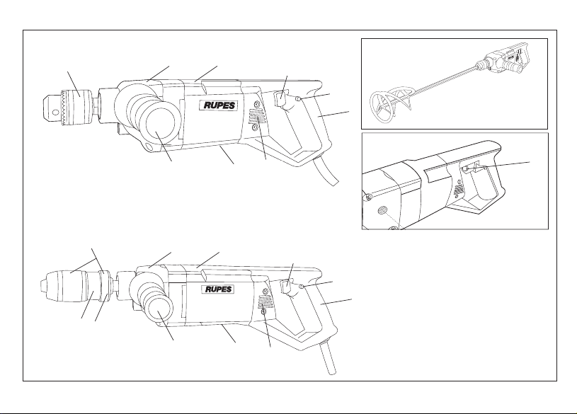
La regolazione del numero di giri si ottiene manovrando il comando
(6) posto sull’interruttore. La regolazione progressiva si ottiene eser-
citando una pressione graduale sull’interruttore.
SOSTITUZIONE DELLE PUNTE
- Aprire le griffe del mandrino svitando l’anello mobile (12) mentre si
mantiene fermo l’anello fisso (13);
- sostituire la punta e serrare come descritto al capitolo “MONTAG-
GIO DELLE PUNTE”.
SOSTITUZIONE DEI MESCOLATORI
- Aprire le griffe del mandrino svitando l’anello mobile (12) mentre si
mantiene fermo l’anello fisso (13);
- sostituire la punta e serrare come descritto al capitolo “MONTAG-
GIO DEI MESCOLATORI”.
UTENSILI DI LAVORO AMMESSI
Punte da trapano in commercio (NL13 - NL16)
Mescolatori con attacco esagonale Ø max 120 mm in commercio
(NL13EMCR - NL16Tool)
MANUTENZIONE
Tutte le operazioni vanno eseguite a spina disinserita.
A fine lavoro, od in caso di necessità, spolverare con getto di aria
compressa il corpo macchina prestando particolare attenzione alla
pulizia delle feritoie di ventilazione del motore.
Non sono ammessi altri interventi da parte dell’utente.
Per la manutenzione e la periodica pulizia delle parti interne, come
spazzole, cuscinetti, ingranaggi, etc. o altre necessità rivolgersi ai
Centri di Assistenza autorizzati.
SICUREZZA ELETTRICA - BASSA TENSIONE
Le prove/verifiche sono state eseguite in accordo alle norme:
EN 60745-1 sicurezza degli utensili elettrici a motore portatili
EN 60745-2-1 norme particolari per trapani.
SCHERMATURA CONTRO I RADIODISTURBI
Le macchine sono conformi agli effetti della prevenzione ed elimina-
zione dei radiodisturbi misurati secondo le norme EN55014-1+
EN55014-2; EN61000-3-2+EN61000-3-3.
FORMAZIONE DI RUMORE
Il livello equivalente di pressione sonora (rumorosità) è di 77 dB
(A),misurati secondo le norme EN ISO 3744 +UNI EN ISO 11203.
Attenzione: indossare adeguati presidi per la difesa dell'udito! (vedi
avvertenze generali).
VALORE MEDIO DELL'ACCELERAZIONE
Il valore quadratico medio dell'accelerazione è inferiore a 2,5 m/sec2 mi-
surati secondo le norme UNI EN 28662 + UNI EN ISO 5349.
GARANZIA
Tutte le macchine costruite dalla RUPES Spa sono garantite per 12
mesi dalla data di acquisto contro difetti di materiale e di fabbricazio-
ne. Le macchine devono essere utilizzate esclusivamente con acces-
sori e ricambi originali RUPES: si declina ogni responsabilità per dan-
ni o incidenti provocati dall’inosservanza della presente norma che
causa anche il decadimento della garanzia.
La garanzia decade qualora non vengano rispettate le prescrizioni del
presente libretto o qualora venga fatto uso improprio della macchina.
Decade altresì se la macchina viene smontata o manomessa o se vi so-
no evidenti danni derivanti da cattiva cura della stessa.
La garanzia è subordinata alla compilazione del tagliando riportato
sull’ultima pagina di copertina del presente libretto d'istruzioni.
In caso di accertato malfunzionamento la macchina, accompagnata
dal certificato di garanzia, dovrà essere consegnata o spedita franco
di porto, non smontata e nell'imballo originale, al fabbricante o ad un
Centro di Assistenza autorizzato riportato nell'elenco allegato al pre-
sente libretto.
In ogni caso la garanzia non dà diritto alla sostituzione della macchina.
La RUPES Spa si riserva di apportare qualsiasi modifica alle caratteri-
stiche tecniche o estetiche dei propri prodotti senza preavviso.
Non si assume nessuna responsabilità per eventuali errori di stampa.
Il presente stampato annulla e sostituisce i precedenti.

7
Dichiariamo sotto la nostra responsabilità che l’utensile elettrico a
motore portatile, al quale fa riferimento il presente manuale, è
conforme ai Requisiti Essenziali delle Direttive:
98/37/CE Macchine
2006/95/CE Bassa Tensione
2004/108/CE Compatibilità elettromagnetica
Le prove/verifiche sono eseguite in accordo alle seguenti
Normative:
EN 60745-1:2008 Sicurezza degli utensili elettrici a motore portatili
EN 60745-2-1: 2008 Norme particolari per trapani e trapani a
percussione
UNI EN ISO 3744: 1997 Acustica. Determinazione dei livelli di
potenza sonora delle sorgenti di rumore.
UNI EN ISO 11203: 1997 Acustica. Rumore emesso dalle macchine
e dalle apparecchiature.
UNI EN 28662-1: 1993 Macchine utensili portatili. Misura delle
vibrazioni sull’impugnatura.
UNI EN ISO 5349-1: 2004 Vibrazioni meccaniche. Misurazione e
valutazione dell’esposizione dell’uomo alle
vibrazioni trasmesse alla mano.
Compatibilità elettromagnetica:
EN 55014-1: 2008 + EN 55014-2: 1998
EN 61000-3-2: 2009 + EN61000-3-3: 2008
Campi elettromagnetici:
EN 50366: 2004
IL PRESIDENTE
G. Valentini
S.p.A
DICHIARAZIONE DI CONFORMITÀTARGHETTA DI IDENTIFICAZIONE DELLA MACCHINA
POSIZIONAMENTO E SIGNIFICATO DEI DATI
1. Tipo della macchina.
2. Tensione nominale di lavoro in Volt (V).
3. Frequenza di lavoro in Hertz (Hz).
4. Corrente assorbita espressa in Ampere (A). Accertarsi che la linea
elettrica cui viene allacciata la macchina possa agevolmente sop-
portare almeno la corrente indicata.
5. Potenza assorbita espressa in Watt (W).
6. Numero di matricola o di serie della macchina.
7. Dati tecnici della macchina.
8. Numero di giri/min.
9. Il doppio quadrato indica che la macchina è in doppio isolamento
e quindi non necessita di messa a terra tramite il cordone di ali-
mentazione.
10. Leggere tutte queste istruzioni prima di azionare il presente
prodotto.
11. Dispositivi di protezione individuale.
12. Il prodotto, in ottemperanza alla Direttiva Europea
2002/96/CE (RAEE) + 2003/108/CE e alla sua attuazione nel dirit-
to nazionale, quando giunge a fine vita, non deve essere disperso
nell’ambiente o gettato tra i rifiuti domestici, ma deve esse smalti-
to presso i centri di raccolta differenziata autorizzati (contattare le
autorità locali competenti per conoscere dove smaltire il prodotto
secondo le norme di legge). Il corretto smaltimento del prodotto
contribuisce alla tutela della salute e alla salvaguardia dell’am-
biente. Lo smaltimento abusivo del prodotto comporta sanzioni a
carico dei trasgressori.
MILANO - ITALY
1
2
910 12
11
6
3
7
45 8

TECHNICAL DATA ENGLISH 8
SAFETY AND ACCIDENT PREVENTION INSTRUCTIONS
The safety and accident prevention instructions are reported in the
“SAFETY INSTRUCTION” booklet which forms an integral part of
these documents; the operating instructions indicate the additional
information required specifically for use of the tool.
Never use the tools without the safety guards.
Any operations carried out on the tool must be effected with the power
supply disconnected.
Before starting the tool, ensure that it is held tightly and not in contact
with the work surface.
Wear clothing suited to the work you are about to perform.
Check the correct drill/bit fastening and alignment.
Check the correct mixing-paddle fastening and alignment.
Due to risks that may arise during polishing, we recommend the con-
stant use of P.S.D. (personal safety devices such as gloves, headpho-
nes, goggles, face masks, etc.) according to laws in force to prevent
or reduce accident probability.
Warning! the appliance continues to work for a few seconds after it
has been switched off!
CORRECT USAGE
These aapliance can be used for:
- NL 13 - NL 16: stone, wood, metal, concrete and composite mate-
rials;
- NL 13EMCR - NL 16 Tool: glue, resins, lack mixing with specific
mixing-paddle .
The machine must not be operated in humin environments or in the
presence of flammable gar or liquids.
Support and secure firmly the workpiece or the mixing material con-
tainer.
In the event or improper use, the user is fully liable for any damages
or accidents.
GENERAL WARNINGS
TYPE
PROTECTION CLASS
OPERATING VOLTAGE
ABSORBED CURRENT
ABSORBED POWER
ROTATION/min.
IN WOOD (Ø MAX)
IN STEEL (Ø MAX)
Ø MAX MIXING PADDLE
CHUCK TYPE
Ø CHUCK
ELECTRONIC SPEED CONTROL
WEIGHT kg
NL16Tool
II
230 V - 50 Hz
2,9 A
600 W
400
-
-
120
KEY-CHUCK
13
-
2,6
NL13EMCR
II
230 V - 50 Hz
2,9 A
600 W
0÷550
-
-
120
KEY-CHUCK
13
YES
2,6
NL16
II
230 V - 50 Hz
2,9 A
600 W
400
32
16
-
SELF-LOCKING
16
-
2,6
NL13
II
230 V - 50 Hz
2,9 A
600 W
550
30
13
-
SELF-LOCKING
13
-
2,6

9
PARTS OF THE TOOL
1 - Identification plate
2 - ON-OFF switch
3 - Switch locking button
4 - Tool body
5 - Rear handle
6 - Gearbox
7 - Side-handle housing
8 - Additinal handle
9 - Chuck
10 - Mobile ring (NL 13 - NL 16)
11 - Fixed ring (NL 13 - NL 16)
12 - Motor ventilation slotts
STARTING UP
Before starting-up the tool, ensure that:
- the packaging is complete and does not show signs of having been
damaged during storage or transport;
- the tool is complete; check that the number and type of
components comply with that reported in this instruction booklet;
- the power supply and socket outlet can support the load reported in
the table and that indicated on the tool identification plate
reproduced and explained on page 11.
ASSEMBLING THE TOOL
ASSEMBLING THE SIDE HANDLE
Screw the handle (8) into the threaded hole on the gearbox. The
handle can be positioned on the right or left of the tool.
FITTING DRILL BITS
1. Keep the chuck still using the fixed ring and unscrew the mobile
ring until the jaws are sufficiently open to hold the drill bit.
2. Lock the drill bit by rotating the upper part of the chuck in a
clockwise direction.
3. Check that the bit does not rotate off-centre.
MIXERS ASSEMBLY
1. Hold the mixer chuck with the stready ring and release the swivel-
ling ring to expand the jaws;
2. lock the mixer paddle turning clocwise the chuck swivelling ring;
3. check the mixer paddle balancing.
BEFORE STARTING THE TOOL
Ensure that:
- the power supply conforms with the characteristics of the tool;
- the power supply cable and plug are in perfect condition;
- the ON/OFF switch works properly though with the power supply di-
sconnected;
- all the parts of the tool have been assembled in the proper manner
and that there are no signs of damage;
- the ventilation slots are not obstructed (7);
- the dust bag is enipty and not torn.
STARTING AND STOPPING
- Starting: push the switch level (2) so that it enters the housing in the
rear handle. To lock the switch in the on position, press the lock but-
ton (3) at the same time.
- Stopping: release the switch. If locked in poition, keep pressing un-
til the look is released.
TEST RUN
Start the machine and check the drill-bit or mixing-paddle alignment.
Otherwise, switch-off the tool immediately and eliminate the cause.

10
ELECRONIC RPM CONTROL (NL13EMCR)
The maximun rpm can be adjusted by rotating the control (6) lo-
cated on the swich. Progressive control is obtained by gradually
increasing the pressure on the swicth.
REPLACING DRILL BITS
- Open the chuck jaws by rotating the mobile ring (12) while kee-
ping the fixed ring (13) still.
- Replace the drill bit and tighten as described in the “FITTING
DRILL BITS” chapter.
MIXER PADDLE REPLACEMENT
- Hold the mixer chuck with the steady ring (13) and release the swiv-
elling ring (12) to expand the jaws;
- replace and lock the mixer paddle as shown in
“MIXER ASSEMBLY”.
USABLE WORKING TOOL
Drill bits avaiable on the market (NL13 - NL16)
Standard hexagonnal attachment mixer paddle Ø max 120 mm
(NL13EMCR - NL16Tool)
MAINTENANCE (aliminata la seconda riga)
All maintenance operations are carried out with the power supply
disconnected.
At the end of each work session, or when required, remove any
dust from the body of the tool using a jet of compressed air,
paying particular attention to the motor ventilation slots.
No other maintenance operations must be undertaken by the
user.
Maintenance and cleaning of the inner parts, like brushes, ball
bearings, gears etc. or others, must be carried out only by an au-
torised customer-service workshop.
ELECTRIC SAFETY - LOW TENSION
The tests have been carried out in accordance with the standard:
EN 60745-1 safety of hand-held electric motor operated tools
EN 60745-2-1 specific drill rules
RADIO SUPPRESSION
The tools are suppressed in accordance for the prevention and
elimination of radio disturbances measured in accordance with
standard: EN55014-1+EN55014-2; EN61000-3-2+EN61000-3-3.
NOISE
The noise level produced is 77 dB, measured according to
regulation EN ISO 3744 + UNI EN ISO 11203.
Warning: wear suitable hearing protections! (see warnings).
MEAN ACCELERATION VALUE
The mean quadratic acceleration value is less than 2,5 m/sec2
measured in accordance with standard UNI EN 28662 + UNI EN
ISO 5349.
GUARANTEE
All tools manufactured by RUPES Spa are guaranteed for 12
months from the date of purchase against fabrication and mate-
rial defects.
All tools must be used only with RUPES original accessories and
spare parts: we refuse all responsibility for damages or accidents
caused by non-observance of this rule which will also cause the
termination of the guarantee.
The guarantee will no longer be valid if the instructions contained
in this booklet are not followed, if the tool is used for purposes
other than that for which it is intended, if it is dismantled, interfe-
red with in any way or damaged due to neglect.
The guarantee will be made valid by filling-in the form on the
inside back cover of this instruction booklet.
If the tool is found to be defective or malfunctions, it should be re-
turned carriage free in one piece in its original packing together
with the guarantee certificate to the manufacturer or to one of the
Assistance Centres listed in the appendix to this booklet.
The guarantee does not automatically imply replacement of the
tool.
RUPES Spa reserves the right to make any technical or design
modification to its products without prior notice.
The manufacturer is not liable for any print errors. This document
voids and replaces previous ones.

11
We declared on our responsability that the hand-held motor
operated tool, which is mentioned in the present operating manual,
is in comformity with the Essential Requirements of Safety of the
following Directives:
98/37/CE Machinery
2006/95/CE Low Tension
2004/108/CE Electromagnetic Compatibility
The tests have been carried out in accordance with following
Standards:
EN 60745-1:2008 Safety of hand-held electric motor operated tools
EN 60745-2-1:2008 Specific drill rules
UNI EN ISO 3744:1997 Acoustics. Determination of sound power
levels of noise sources.
UNI EN ISO 11203: 1997 Acoustics. Noise emitted by machinery and
equipment.
UNI EN 28662-1: 1993 Hand-held portable power tools.
Measurement of vibrations at the handle.
UNI EN ISO 5349-1: 2004 Mechanical vibration. Measurement and
evaluation of human exposure to hand-
transmitted vibration.
Electromagnetic compatibility:
EN 55014-1: 2008 + EN 55014-2: 1998
EN 61000-3-2: 2009 + EN61000-3-3: 2008
Electromagnetic fields:
EN 50366: 2004
IL PRESIDENTE
G. Valentini
S.p.A
CONFORMITY DECLARATIONTOOL IDENTIFICATION PLATE
POSITION AND MEANING OF INFORMATION
1. Type of tool.
2. Nominal working voltage in Volts (V).
3. Working frequency in Hertz (Hz).
4. Absorbed current in Amperes (A). Ensure that the power supply to
which the tool is connected can easily tolerate the indicated
current as a minimum.
5. Absorbed power expressed in Watts (W).
6. Tool code or serial number.
7. Technical data of the tool.
8. Maximum rpm
9. The double square indicates that the tool is doubly insulated and
therefore does not require earthing through the power supply
cable.
10. Read all these instructions before operating this product and
save these instructions.
11. Personal safety devices.
12. At the end of its useful life, the product, pursuant to European
Directive 2002/96/CE (RAEE) + 2003/108/CE and its
implementation in national law, must not be released into the
environment or thrown away as domestic waste, but must be
disposed of at authorised recycling centres (contact the relevant
local authorities for a list of places where the product may be
disposed of according to the law).Disposing of the product
correctly contributes to protecting human health and
safeguarding the environment. Any illegitimate disposal of the
product will be punishable by law.
MILANO - ITALY
1
2
910 12
11
6
3
7
45 8

12
CARACTERISTIQUES TECHNIQUES FRANÇAIS 12
INSTRUCTIONS RELATIVES A LA SECURITE
ET A LA PROTECTION CONTRE LES ACCIDENTS DU TRAVAIL
Les instructions relatives à la sécurité et à la protection contre les
accidents du travail sont contenues dans le fascicule "INDICATIONS
RELATIVES A LA SECURITE" qui fait partie intégrante de la présente
documentation; le livret d'instructions relatives à l'utilisation indique
uniquement les informations complémentaires qui sont étroitement
linées à l'utilisation spécifique de la machine. Ne jamais faire
fonctionner les outils sans avoir monté les dispositifs de protection.
Chaque opération effectuée sur la machine ait lieu aprés que la fiche
ait étè dèbranchèe. Avant sa mise en marche, la machine soit
empoignée solidement et qu’elle ne soit pas en contact avec la
surface de travail. Portez des vêtements adaptés au travail que vous
devez exécute.
Contrôler si les forets sont correctement montés et serrés.
Contrôler si le malaxeur est correctement monté et serré.
A cause des risques qui peuvent survenir durant le ponçage, il est
conseillé de toujours utiliser tous les D.P.I. (dispositifs de protection
individuels tels que gants, oreillettes, lunettes de protection, masques
de protection des voies respiratoires, etc.) selon les normes en
vigueur pour prévenir ou réduire les risques d'accidents.
Attention ! L'outil continue à fonctionnner pendant quelques secon-
des après l'arrêt!
UTILISATION CONFORME
Les machines doivent être utilisées pour :
- NL13 - NL16: perçage de pierre, bois, métal, béton et de matériaux
synthétiques;
- NL13EMCR - NL16TooL: mélange de colles, résines, peintures
avec les malaxeurs prévus à cet effet.
La machine ne doit jamais fonctionner ni dans une ambiance humide
ni en présence de gaz ou de liquides inflammables.
Contrôler si la pièce à percer ou le récipient du matériau à mélanger
est suffisamment fixé.
En cas d'utilisation non conforme aux buts prévus, l'utilisateur sera te-
nu responsable des éventuels dommages et accidents.
RECOMMANDATIONS GENERALES
TYPE
CLASSE DE PROTECTION
TENSION DE TRAVAIL
COURANT ABSORBEE
PUISSANCE ABSORBEE
TOURS/min.
TROU SUR LE BOIS (Ø MAX)
TROU SUR ACIER (Ø MAX)
Ø MAX MALAXEUR
TYPE DE MANDRIN
Ø MANDRIN
PROTECTION ELECTRONIQUE
MASSE kg
NL16Tool
II
230 V - 50 Hz
2,9 A
600 W
400
-
-
120
CRÉMAILLÈRE
13
-
2,6
NL13EMCR
II
230 V - 50 Hz
2,9 A
600 W
0÷550
-
-
120
CRÉMAILLÈRE
13
OUI
2,6
NL16
II
230 V - 50 Hz
2,9 A
600 W
400
32
16
-
SERRAGE UTOMATIQUE
16
-
2,6
NL13
II
230 V - 50 Hz
2,9 A
600 W
550
30
13
-
SERRAGE AUTOMATIQUE
13
-
2,6

13
PARTIES DE LA MACHINE
1 - Étiquette d’identification
2 - Interrupteur de mise en marche - arrêt
3 - Bouton de blocage de l’interrupteur
4 - Corps machine
5 - Poignée arrièr
6 - Commande régulateur élecronique de vitesse (NL 13EMCR)
7 - Carter renvoi d’angle
8 - Emplacement pour coller la poignée aux
9 - Mandrin
10 - Bague mobile (NL 13 - NL 16)
11 - Bague fixe (NL 13 - NL 16)
12 - Fentes puor ventilation moteur
MISE EN SERVICE
Avant de mettre la machine en service, s'assurer que:
- l'emballage est intègre et qu'il ne montre aucun signe
d'endommagements dus au transport et au stockage;
- la machine est complète; s'assurer que le nombre et la nature des
composants sont conformes aux indications contenues dans le
présent livret d'instructions;
- la source d'énergie et les prises de courant à disposition peuvent
supporter la charge indiquée dans le tableau et sur la plaquette
d'identification de la machine, dont le fac-similé et les explications
relatives sont fournis page 15.
MONTAGE DE LA MACHINE
MONTAGE DE LA POIGNEE AUXILIAIRE
Visser la poingée (8) sur le carter renvoi d’angle en la fixant dans les
trous filetés.La poingée peut etre mise à droite ou à gauche de la ma-
chine.
MONTAGE DES MECHES
1. En bloquant le mandrin à l’aide de la bague fixe, dévisser la bague
mobile jusqu’à ce que les griffes présentent une overture suffisante
afin d’y loger la méche:
2. bloquer la mèche en faisant tourner dans le sens des aigulles d’u-
ne montre la partie supérieure du mandrin;
3. S’assureur que la mèche ne soit pas décentrée.
MONTAGE DES MALAXEURS
1. En immobilisant le mandrin à l’aide de l’anneau fixe, dévisser l’an-
neau mobile jusqu’à ce que les griffes laissent une ouverture suffi-
sante pour loger le malaxeur ;
2. Bloquer le malaxeur en tournant la partie supérieure du mandrin
dans le sens des aiguilles d’une montre ;
3. Contrôler si le malaxeur tourne de façon bien centrée.
AVANT LA MISE EN SERVICE
S'assurer que:
- la source d'énergie est conforme aux caractéristiques de la machine;
- le câble d'alimentation et la fische relative sont en parfait état;
- l'interrupteur de mise en marche/arrêt est efficace en agissant ce-
pendant lorsque la fiche est débranchée;
- tous les composants de la machine sont montès correctement et ne
présentent pas de signes d'endommagement;
- les fentes de ventililation ne sont pas bouchées (7);
- le sac à poussière est vide et n’est pas lacéré.
MISE EN MARCHE ET ARRET
- Mise en marche: pousser le levier de l’interrupteur (2) de façon à ce
qu’il rentre dans le siège de la poingée arrière. Pour le bloquer en
position “ouvert”, pousser en meme temps le bouton de bloccage
(3);
- Arrêt: recacher l’interrupteur. S’il est bloqué, appuyer dessus ju-
squ’à ce qu’il débloque.
FONCTIONNEMENT D'ESSAI
Démarrer la machine et contrôler que le foret de la perceuse ou le
malaxeur ne soit pas décentré
Dans le cas contraire, débrancher immediatement et éliminer les
anomalies.

14
REGLAGE ELECTRONIQUE DU NOMBRE DE TOURS
(NL 13EMCR)
Le réglage du nombre de tours maximum s’effectue en manoeuvrant
la commande (6) située sur l’interrupteur. Le réglage progressif s’ob-
tien en exerçant une pression graduelle sur l’interrupteur.
REMPLACEMENT DES MECHES
- Ouvrir les griffes du mandrin en dévissant la bague mobile (12 tout
en bloquant la bague fixe (13);
- replacer la mèche et serrer comme décrit au chapiter “MONTAGE
DES MECHES”.
REMPLACEMENT DES MALAXEURS
- Ouvrir les griffes du mandrin en dévissant l’anneau mobile (12) tout
en immobilisant l’anneau fixe (13);
- remplacer le foret et serrer de la façon décrite dans le chapitre «
MONTAGE DES MALAXEURS ».
OUTILS DE TRAVAIL ADMIS
Méches puor perceuse en vente dans le commerce (NL 13 - NL 16).
Malaxeurs avec raccord hexagonal Ø maxi 120 mm dans le commer-
ce (NL13EMCR - NL16Tool)
ENTRETIEN
Toutes les opérations doivent étre effectuées la fiche étant débran-
chée.
A la fin du travail et en cas de nècessitè, dèpoussièrer le corps de la
machine à l’aide d’un jet d’air comprimè en faisant particuliérement
attention au nettoyage des fentes de ventilation du moteur.
Aucune autre intervention de l’utilisateur n’est admise.
Tous travaux d’entretien et travaux de polissage des piéces internes,
comme les brosses, coussinet, engrenages etc., doivent être effe-
cuès par un atelier de réparation autorisè.
SECURITE ELECTRIQUE - BASSE TENSION
Les proves/verifies out eté executés en accord a les normes:
EN 60745-1 securité des outils électrique a moteur portatives
EN 60745-2-1 Règles particulières pour les perceuses
PROTECTION CONTRE LES PARASITES RADIO
Les machines sont conformes à les effets de la prévention et
des parasites radio mesures en accord a les normes EN55014-1+
EN55014-2; EN61000-3-2+EN61000-3-3.
FORMATION DU BRUIT
Le niveau équivalent de la pression sonore (niveau de bruit) est de
77dB, mesurés conformément aux normes EN ISO 3744 + UNI EN
ISO 11203.
Attention: porter les dispositifs de protection de l'ouïe adéquats!
(Cf. avertissements généraux).
VALEUR MOYENNE DE L'ACCELERATION
La valeur quadratique moyenne de l'accèlération est inférieure à
2,5 m/sec2mesuré en accord a les normes UNI EN 28662 + UNI EN
ISO 5349.
GARANTIE
Toutes les machines construites par la Société RUPES Spa sont ga-
ranties pendant 12 mois à compter de la date d’achat contre les dé-
fauts matériau et de fabrication.
Les machines ne doivent être utilisées qu'avec les pièces détachées
et les accessoires originaux RUPES: nous déclinons toute responsa-
bilité en cas d'accidents ou de dégâts matériels provoqués par le
non-respect de cette norme, qui entraînera en outre l'annulation de la
garantie. La garantie prend fin en cas de non-respect des prescrip-
tions du présent livret ou en cas d’utilisation impropre de la machine.
Elle prend fin également si la machine est démontée ou modifiée ou
en cas de dommages évidents dérivant d’un mauvais entretien.
La garantie est subordonnée au remplissage du coupon qui se
trouve à la dernière page de couverture du présent livret d’in-
structions. En cas de mauvais fonctionnement, la machine, accom-
pagnée de son certificat de garantie, devra être remise ou envoyée
en port payé, non démontée et dans son emballage d’origine, au fa-
bricant ou à un Centre d’Assistance agrée indiqué sur la liste an-
nexée au présent livret.La garantie ne donne pas en aucun cas droit
au remplacement de la machine.RUPES Spa se réserve le droit de
modifier sans préavis les caractéristiques techniques ou esthétiques
des ses produits. Nous déclinons toute responsabilité quant aux er-
reurs d'impression éventuelles. Ce document annule et remplace
tous les précédents.

PLAQUETTE D’IDENTIFICATION DE LA MACHINE
EMPLACEMENT ET SIGNIFICATION DES DONNEES
1. Type de la machine.
2. Tension nominale de travail en Volts (V).
3. Fréquence de travail en Hertz (Hz).
4. Courant absorbé exprimé en Ampéres (A). S’assurer que la ligne
électrique à laquelle la machine est branchée pourra aisément
supporter au moins le courant indiqué.
5. Puissance absorbée exprimée en Watts (W).
6. Numéro d’immatriculation ou de série de la machine.
7. Caractéristiques techniques de la machine.
8. Nombre de tours/min.
9. Le double carré indique que la machine est à double isolement et
que par conséquent, la mise à la terre par le cordon d’alimenta-
tion n’est pas nècessaire.
10. Lire toutes ces instructions avant de mettre en marche le
présent produit.
11. Dispositifs de protection individuels.
12. Conformément à la Directive européenne 2002/96/CE
(RAEE) + 2003/108/CE et à sa mise en application dans la législa-
tion nationale, les vieux produits ne doivent être jetés ni dans la
nature ni avec les ordures ménagères mais être remis à un centre
de collecte sélective autorisé (adressez-vous à votre mairie pour
savoir où vous débarrasser du produit conformément à la loi).L’é-
limination correcte du produit contribue à la protection de la santé
et de l’environnement. En n’éliminant pas le produit conformé-
ment à la loi en vigueur vous vous exposez à des sanctions.
15
Nous déclarons sous notre responsabilité que l’outil électrique à
moteur portable, auquel se réfère le présent manuel, est conforme
aux Conditions Essentielles des Directives :
998/37/CE Machines
2006/95/CE Basse Tension
2004/108/CE Compatibilité électrimagnétique
Les proves/vérifiés out été exécutés en accord a les vigueurs Régles
Harmonisés Européennes
Basse Tension:
EN 60745-1 Sécurité des outils électrique a moteur portatives
EN 60745-2-1: 2008 Règles particulières pour les perceuses
UNI EN ISO 3744:1997 Acoustique. Détermination des niveaux de
puissance sonore des sources du bruit.
UNI EN ISO 11203:1997 Acoustique. Bruit émis par les machines et
les équipements.
UNI EN 28662-1:1993 Machines-outils portables. Mesure des
vibrations au niveau de la poignée.
UNI EN ISO 5349-1:2004 Vibrations mécaniques. Mesure et
évaluation de l’exposition de l’homme aux vibrations
transmises à la main.
Compatibilité électrimagnétique:
EN 55014-1: 2008 + EN 55014-2: 1998 EN 61000-3-2: 2009 +
EN61000-3-3: 2008
Champs électromagnétiques:
EN 50366: 2004
IL PRESIDENTE
G. Valentini
S.p.A
DÉCLARATION DE CONFORMITÉ
MILANO - ITALY
1
2
910 12
11
6
3
7
45 8

16
TYP
SCHUTZKLASSE
SPANNUNG
STROMAUFNAHME
LEISTUNGSAUFNAHME
UMDREHUNGEN U/min
BOHRLEISTUNG IN HOLZ (MAX. DURCHM.)
BOHRLEISTUNG IN STAHL (MAX. DURCHM.)
GESCHWIMDIGKEITSREGULIERUNG
TYP BOHRSPINDEL
ABMESSUNGEN BODENPLATTE mm
SBOHRFUTTER - Ø
GEWICHT kg
SICHERHEITS- UND UNFALLVERHÜTUNGSVORSCHRIFTEN
Die Sicherheits- und Unfallverhütungsvorschriften sind im
beiliegenden Helft "HINWEISE ZUR SICHERHEIT" enthalten, welches
vollwertiger Bestandteil der vorliegenden Dokumentation ist. Diese
Gebrauchsanleitung nennt daher nur die Zusatzinformationen, die
den spezifischen Einsatz dieses Gerätes betreffen. Alle Arbeiten an
der Maschine nur bei gezogenem Netzstecker ausführen. Werkzeuge
niemals ohne aufmontierte Schutzvorrichtungen betreiben.
Die Maschine vor dem Einschalten fest in der Hand halten. Sie darf
die zu bearbeitende Fläche nicht berühren. Tragen Sie für die durch-
zuführenden Arbeiten geeignete Kleidung.
Überprüfen Sie die korrekte Bit-Befestigung und die Justierung
Überprüfen Sie die korrekte Befestigung und Justierung des Rührsta-
bes.
Aufgrund der mit dem Schleifen verbundenen Risiken wird empfoh-
len, entsprechend den geltenden Richtlinien zur Unfallverhinderung
bzw. -reduzierung stets die gesamte P.S.A. (persönliche Schutz-Au-
srüstung, wie zum Beispiel Handschuhe, Ohrschützer, Schutzbrillen,
Atemschutzmaske, usw.) zu tragen.
Achtung! Das Werkzeug läuft nach dem Ausschalten noch für einige
Sekunden weite!
BESTIMMNGSGEMÄßE VERWENDUNG
Dieses Gerät kann benutzt werden für:
-NL 13 - NL 16: Stein, Holz, Metall, Beton und Verbundsstoffe;
-NL 13EMCR - NL 16Tool: Klebstoffe, Harze, Rühren von
Anstrichstoffen mit speziellen Rühraufsätzen.
Wergen der elektrischen Sicherheit, dürfen die Maschinen nicht
feucht sein und nicht in feuchter Umgebund betrieben werden.
Gewährleisten Sie den sicheren Stand / Befestigung des Werkstückes
bzw. des Behälters.
Überprüfen, ob das Werkstück ausreichend befestigt ist.
Wird das Gerät für nicht vorgesehene Zwecke benutzt, übernimmt der
Benutzer jede Verantwortung für eventuelle Schäden oder Unfälle.
ALLGEMEINE HINWEISE
TECHNISCHE DATEN DEUTSCH 16
NL16Tool
II
230 V - 50 Hz
2,9 A
600 W
400
-
-
120
SCHNELLESPANNBOHRFUTTER
13
-
2,6
NL13EMCR
II
230 V - 50 Hz
2,9 A
600 W
0÷550
-
-
120
SCHNELLESPANNBOHRFUTTER
13
YES
2,6
NL16
II
230 V - 50 Hz
2,9 A
600 W
400
32
16
-
SCHNELLSPANNSYSTEM
16
-
2,6
NL13
II
230 V - 50 Hz
2,9 A
600 W
550
30
13
-
SCHNELLSPANNSYSTEM
13
-
2,6

17
BAUTEILE DER MASCHINE
1 - Schild mit Geräte-Kenndaten
2 - EIN/AUS-Schalter
3 - Arretiertaste des EIN/AUS-Schalters
4 - Drehzahlregler
5 - Umschaltung Rechts-/Linkslauf
6 - Gerätegehäuse (NL 13EMCR)
7 - Mech. Schaltgetriebe
8 - Seitlicher Handgriff Gehäuse
9 - Getriebe Seitlicher Handgriff
10 - Bohrfutterschlüssel (NL 13 - NL 16)
11 - Fester Ring (NL 13 - NL 16)
12 - Lüftungsschlitze Motor
INBETRIEBNAHME
Vor einer Inbetriebnahme des Gerätes sollten Sie sicherstellen:
- daß die Verpackung unversehrt ist und keine Beschädigungen
durch Transport bzw. Lagerung aufweist;
- daß das Gerät vollständig ist, also Anzahl und Art der
Gerätekomponenten mit den Angaben in dieser
Gebrauchsanleitung überein stimmen;
- daß Stromnetz und Steckdosen für die in der Tabelle bzw. auf dem
Geräteschild (vgl. Abbildung u. Beschreibung des Geräteschilds auf
Seite 19) genannte Stromlast ausgelegt sind.
ZUSAMMENBAU DER MASCHINE
BEFESTIGUNG DES ZUSATZHANDGRIFFS
Den Handgriff (8) auf das Getride aufshrauben, dazu die vorbereite-
ten Gewendebohrungenverweden. Der Griff kann wahlweise an der
rechten bzw. linken Seite montiert werde.
EINSETZEN DER BOHRER
1. Die Bohrspindel am festen Ring festhalten und der drehbare ring
losdrehe, bis sich die Spannbacken ausreichend geöffnet haben,
um den Boher aufnehmen zu können;
2. Das vordere Ende der Bohrspindel drehen und damit den Bohrer
einspannen;
3. Überprüfen, daß der Boher nicht unrund läuft.
MONTAGE RÜHRAUFSATZ
1. Halten Sie das Bohrfutter fest und lösen Sie den Feststellring um
die Spannbacken zu lösen.
2. Befestigen Sie den Rühraufsatz durch festziehen des Bohrfutter im
Uhrzeigersinn.
3. Kontrollieren Sie die Balance und die Wuchtung.
VOR DER INBETRIEBNAHME
Stellen Sie folgende Punkte sicher:
- das Stromntez entspricht den Gerätekenndaten.
- Anschlußkabel und-Stecker sind in ordnungsgemäßem Zustand.
- der EIN/AUS- Schalter funktioniert einwandfrei. Zur Überprüfung die
in Kapitel “Inbetriebnahme” beschriebenen Schaltstellungen - aller-
dings bei gezogenem Netztstecker - ausprobieren.
- Sämtliche Gerätekomponenten sind ordnungsgemäß montiert und
zeigen keine. Anzeichen von Beschädigung.
- die Lüftungsshlitze sind nicht verstopft (7).
EINSCHALTEN UND AUSSCHALTEN
- Einschalten: den Schalter (2) drücken, bis er in die Vertiefung im hin-
teren Handgriff eingeschoben ist. Falls er in EIN-Stellung arretiert wer-
den soll, gleichzeitig den Arretierknopf (3) drücken.
- Ausschalten: den Schalter loslassen. Wenn dieser arretiert ist, den
Schalter so weit eindrücken, bis er spürbar entriegelt ist.
TESTLAUF
Starten Sie die Maschine und kontrollieren Sie den Sitz des Bits oder
des Rühraufsatzes.
Andernfalls das Gerät sofort ausschalten und die Störung beheben.

18
ELEKTRONISCHE DREHZZAHLREGULIERUNG (NL 13EMCR)
Die Einstellung der Höchstdrehzahl nimmit man über die Stellvorrich-
tung (6) auf dem Schalter vor. Die abgestufte Einstellung erzelt man
durch zunehmenden Druck auf diesen Schalter.
AUSWECHSELN DER BOHRER
- Die Spannbacken des Bohrfutter öffnen, indem man den drehbaren
Ring (12) losdreht und gleichzeitig den festen Ring (13) festält;
- den neune bohrer einsetzen und wie im Abschnitt “EINSETZEN
DER BOHRER” festspannen.
WECHSEL RÜHRAUFSATZ
- Halten Sie das Bohrfutter (13) fest und lösen Sie den Feststellring
(12) um die Spannbacken zu lösen.
- Tauschen und befestigen Sie den Rühraufsatz wie unter „MONTA-
GE RÜHRAUFSATZ“ beschrieben.
ZULÄSSIGE WERKZEUGE
- Standard Bit-Aufsätze (NL 13 – NL 16)
- Standard Sechskant-Rühraufsatz Ø 120 mm (NL 13EMCR - NL
16Tool)
PFLEGE DES GERÄTES
Sämtliche Eingriffe bei gezogenem Netzstecker ausführen.
Regelmäßig den Staubfengsack (9) entleeren.
Das Gerät nach der Arbeit sowie bei Bedarf mit Druckluft von Staub
befreien. Besonders darauf achten, daß die Lüftungsschlitze des
Motors sauber sind.
Sonstige Eingriffe durch den Geräteanwender sind nicht zulässig.
Für die Wartung und die periodische Reinigung von den inneren Tei-
len z. B: Bürsten, Lagern, Zahnrädern usw. oder andere Bedürfnisse
wenden Sie sich bitte an einer autorisierten Kundendienststelle an.
ELEKTRISCHE SICHERHEIT - NIEDERSPANNUNG
Die Tests wurden nach den Anforderungen der zur Zeit gültigen
Normen ausgeführt:
EN 60745-1 sicherheit für tragbare elektrisch betriebe Maschinen
EN 60745-2-1 Besondere Anforderungen für Bohrmaschinen und
Schlagschrauber.
FUNKENTSTÖRUNG
Die Geräte erfüllen die Vorschriften der EG-Richtlinie 89/336 zur
Vorbeugung und Beseitigung von Funkstörungen Messung nach
Norm: EN55014-1+EN55014-2; EN61000-3-2+EN61000-3-3.
SCHALLPEGEL
Der Schalldruckpegel (Geräuschentwicklung) der Maschine
entspricht 75 dB, gemessen gemäß EN ISO 3744 + UNI EN ISO
11203.
Achtung: Während des Betriebs angemessenen Gehörschutz tra-
gen! (siehe allgemeine Hinweise)
MITTLERE BESCHLEUNIGUNG
Die mittlere quadratische Beschleunigung liegt unter 2,5 m/s2
Messung nach UNI EN 28662 + UNI EN ISO 5349.
GARANTIE
Für alle von ihr hergestellten Geräte leistet die Fa. RUPES Spa
Gewähr im von Mangeln, die innerhalb von 12 Monaten ab dem Kauf-
datum aufgrund Material-oder Fabrikationsfehlern auftreten.
Die Maschinen dürfen ausschließlich mit Originalzubehör und Origi-
nalersatzteilen von RUPES betrieben werden: Das Unternehmen haf-
tet nicht für Unfälle oder Schäden, die auf die Nichtbeachtung dieser
Bestimmung zurückzuführen sind, die außerdem zum unverzügli-
chen Verfall der Garantie führt.
Der Garantieanspruch entfällt bei unsachgemäßem Gebrauch des
Gerätes oder der Nichteinhaltung dieser Gebrauchasanleitung.
Er entfällt ebenfalls, wenn das Gerät demontiert bzw. umgerüstet wur-
de oder sichtbare Schäden infolge mangelhafter Pflege aufweist.
Die Inansprunchnahme der Garantieleistung ist nur möglich,
wenn der Abschnitt auf der vorletzten Umschlagseite dieser Ge-
brauchsanleitung ausgefüllt ist.
Im Fall einer nachweislichen Funktiosstörung muß das Gerät dem
Hersteller komplett montiert, originalverpackt und mit beiliegender
Garantiekarte fracht und portofrei übergeben bzw. zugesendet wer-
den. Die Übergabe an ein autorisiertes Kundendienstzentrum (siehe
beiliegendes Verzeichnis) ist ebenfalls möglich. In keinem Fall leitet
sich aus dem Garantieanspruch ein Rechtsanspruch auf die Erset-
zung des Gerätes ab.
Die Fa. RUPES SpA behält sich das Recht vor, ohne Vorankündigung
technische und ästhetische Änderungen an ihren Produkten vorzu-
nehmen. Das Unternehmen haftet nicht für eventuelle Druckfehler.
Vorliegendes Dokument annulliert und ersetzt alle früheren Veröffen-
tlichungen.

KENNDATENSCHILD DES GERÄTES
ANORDNUNG UND BEDEUTUNG DER ANGABEN
1. Gerätetyp.
2. Nenn-Anschlußspannung in Volt (V).
3. Frequenz in Hertz (Hz).
4. Stromaufnahme in Ampere (A).Es ist sicherzustellen, daß die
Stromleitung, an die das Gerät angeschlossen werden soll, min-
destens diese Strombelastung problemlos aushält.
5. Leistungsaufnahme in Watt (W).
6. Geräte- oder Seriennummer.
7. Technische Gerätedaten.
8. Drehzahl in Umdrehungen/Min.
9. Das doppelte Quadrat zeigt an, daß das Gerät zweifach schutzi-
soliert ist und daher keine Erdung über das Anschlußkabel erfor-
derlich ist.
10. Lesen Sie diese Hinweise aufmerksam durch, bevor Sie das
vorliegende Produkt in Betrieb nehmen.
11. Persönliche Schutz-Ausrüstung.
12. Das Produkt darf entsprechend der Europäischen Richtlinie
2002/96/CE (RAEE) + 2003/108/CE und deren Umsetzung in der
nationalen Gesetzgebung am Ende seiner Lebensdauer nicht
weggeworfen oder im Hausmüll entsorgt werden, sondern muss
bei den autorisierten Zentren zur Abfalltrennung abgegeben wer-
den (wenden Sie sich an die zuständigen Behörden vor Ort, um
zu erfahren, wo das Produkt nach den gesetzlichen Bestimmun-
gen zu entsorgen ist). Die korrekte Entsorgung des Produkts trägt
zum Schutz der Gesundheit und der Umwelt bei. Die missbräuch-
liche Entsorgung des Produkts zieht Sanktionen zu Lasten des
Verursachers nach sich.
19
MILANO - ITALY
1
2
910 12
11
6
3
7
45 8
Wir bestätigen in unserer Verantwortung das die Handgehaltenen
Motorwerkzeuge, die in diesem Betriebshandbuch beschrieben wer-
den, ist in Übereinstimmung mit den wesentlichen Bestimmungen für
die Sicherheit der folgenden Direktiven:
2006/42/CE Maschinenrichtlinie
2006/95/CE Niederspannung
2004/108/CE Elektromagnetische Verträglichkeit
Die Tests wurden ausgeführt nach den Anforderungen der zur Zeit
gültigen europäischen Harmonisierungsregeln Niederspannung:
EN 60745-1: 2008 Sicherheit für tragbare elektrisch betriebene
Maschinen
EN 60745-2-1: 2008 Besondere Anforderungen für Bohrmaschinen
und Schlagschrauber.
UNI EN ISO 3744:1997 Akkustik. Festsetzung des Geräuschlevel
und Lärmpegel.
UNI EN ISO 11203: 1997 Akkustik. Von Maschinen und Anlagen ab
gegebener Lärmpegel.
UNI EN 28662-1: 1993 Handgehaltene motorbetriebene Maschinen -
Messung mechanischer Schwingungen am
andgriff.
UNI EN ISO 5349-1: 2004 Mechanische Schwingungen. Messung
und Auswertung von Auswirkungen auf die
Hand übertragenen Vibrationen.
Elektromagnetische Verträglichkeit:
EN 55014-1: 2008 + EN 55014-2: 1998
EN 61000-3-2: 2009 + EN 61000-3-3: 2008
Elektromagnetische Felder:
EN 50366: 2004
IL PRESIDENTE
G. Valentini
S.p.A
KONFORMITÄTSERKLÄRUNG

20
DATOS TECNICOS ESPAÑOL 20
INSTRUCCIONES PARA LA SEGURIDAD
Y LA PREVENCION DE ACCIDENTES
Las instrucciones para la seguridad y la prevención de accidentes se
ilustran en el opúsculo "INDICACIONES PARA LA SEGURIDAD" que
forma parte de la presente documentación. El manual de
instrucciones para el uso ilustra solamente aquellas informaciones
adicionales estrictamente relacionadas con el uso especifico de la
máquina. No hacer funcionar nunca las herramientas sin montados
los dispositivos de protección. Que cada operación en la máquina
sea ejecutada con el enchufe desconectado. Que antes de
accionarla, la máquina estè firmemente empuñada y no estè contacto
con la superficie de trabajo. Llevar prendas adecuadas para el trabajo
que se va a realizar.
Compruebe que la broca se encuentra correctamente sujeta,
alineada y centrada.
Compruebe que la varilla del mezclador se encuentra correctamente
sujeta, alineada y centrada.
Debido a los riesgos que pueden surgir durante el alisado, se
recomienda utilizar siempre todos los D.P.I. (dispositivos de
protección individuales, como guantes, cascos, gafas protectoras,
caretas para proteger las vías respiratorias, etc.) conforme a las
normas de ley vigentes a fin de precaver o reducir las posibilidades
de accidentes.
¡Atención! La herramienta ¡sigue funcionando por unos segundos
después del apagado!
USO CONFORME A LO DETERMINADO
Estas herramientas pueden ser empleadas para:
- NL 13 – NL 16: Piedra, madera, metal, hormigón y composites;
- NL13EMCR – NL16Tool: Pegamento, resinas, batido de lacas con
una varilla mezcladora específica.
La máquina no debe funcionar en ambientes húmedos ni ante gases
o líquidos inflamables.
Sujete y asegure firmemente la pieza a trabajar o el contenedor del
material a batir.
En caso de utilización no conforme a las finalidades previstas, el
usuario asume todas las responsabilidades ante eventuales daños y
accidentes.
ADVERTENCIAS GENERALES
TIPO
CLASE DE PROTECCION
TENSION DE OPERACION
CORRIENTE ASSORBIDA
POTENCIA ASSORBIDA
REVOLUCIONES/min.
PERFORACIÓN EN MADERA (Ø MAX)
PERFORACIÓN EN ACERO (Ø MAX)
Ø MAX MEZCLATOR
TIPO DE PORTABROCAS
CAPACIDAD DEL PORTABROCAS
REGOLAZIONE ELETTRONICA
MASSA kg
NL16Tool
II
230 V - 50 Hz
2,9 A
600 W
400
-
-
120
DE LLAVE
13
-
2,6
NL13EMCR
II
230 V - 50 Hz
2,9 A
600 W
0÷550
-
-
120
DE LLAVE
13
SI
2,6
NL16
II
230 V - 50 Hz
2,9 A
600 W
400
32
16
-
DE CIERRE RÁPIDO
16
-
2,6
NL13
II
230 V - 50 Hz
2,9 A
600 W
550
30
13
-
DE CIERRE RÁPIDO
13
-
2,6
This manual suits for next models
3
Table of contents
Languages:
Other Rupes Drill manuals
Popular Drill manuals by other brands

Bosch
Bosch Professional GSR 12V-35 FC Original instructions

Skil
Skil 2815 parts list

Ryobi
Ryobi RPD1200-K Original instructions

Baier
Baier BDB 822AP Translation of the original instruction manual

Panasonic
Panasonic EY6803 - HAMMER DRILL DRIVER 12V operating instructions

Skil
Skil 6271 Original instructions