Ruskin Z2000RT Instruction Manual

Zone Control Solutions
Installation & Maintenance Manual
Model: Z2000RT
Wall Mount Thermostat
II-Z2000RT-613/New ALL STATED SPECIFICATIONS ARE SUBJECT TO CHANGE WITHOUT PRIOR NOTICE OR OBLIGATION ©RUSKIN 2013

Table of Contents
Primary Application & Introduction..................................................................................................................2
Terminal Designations & Installation.......................................................................................................... 2&3
Wiring Diagrams...............................................................................................................................................4
Key Functions and Setup......................................................................................................................5,6,7 & 8
Specifications ...................................................................................................................................................8
Contact Ruskin Air & Sound Control, Air Measuring Product Sales
3900 Dr. Greaves Road Grandview, MO 64030.
Telephone: 816-761-7476
www.ruskin.com
PRIMARY APPLICATION AND INTRODUCTION
Ruskin model Z2000RT thermostat is designed to work with the Z2000 modulating zone control system and all Ruskin “Stand-
Alone” zone control solutions. Please take time to read and understand this manual so that installation and testing is undertaken in
an efficient and effective manner. Although great care has been taken in the preparation of this manual, Ruskin takes no
responsibility for errors or omissions contained herein. It is the responsibility of the installer to ensure that this thermostat and the
equipment connected to it operate in a safe and efficient manner.
Due to ongoing product enhancement, Ruskin reserves the right to change the specifications of the Z2000RT without notice.
DISASSEMBLY
Insert a small coin in the release slot located on the bottom of the thermostat. Gently twist the coin to
release the thermostat from the sub-base. Avoid twisting the case, as this may stress the LCD and cause
it to crack or bend the terminal pin connectors.
TERMINAL DESIGNATIONS
The Z2000RT has dedicated screw terminals located on the sub-base to facilitate ease of wiring to the
actuator logic card mounted on all Z2000 and “Stand-alone” dampers. When wiring the Z2000RT to the
actuator logic card, use standard 18-8 thermostat wire (verify with local codes if plenum rated wire is
required).
2
! WARNING
THIS ACCESSORY IS TO BE INSTALLED BY A QUALIFIED SERVICE TECHNICIAN. TO AVOID UNSATISFACTORY OPERATION
OR DAMAGE TO THE PRODUCT AND POSSIBLE UNSAFE CONDITIONS, INCLUDING ELECTRICAL SHOCK AND FIRE, THE
INSTALLATION INSTRUCTIONS PROVIDED WITH THIS ACCESSORY MUST BE STRICTLY FOLLOWED AND THE PARTS
SUPPLIED USED WITHOUT SUBSTITUTION. DAMAGE TO THE PRODUCT RESULTING FROM NOT FOLLOWING THE
INSTRUCTIONS OR USING UNAUTHORIZED PARTS MAY BE EXCLUDED FROM THE MANUFACTURER’S WARRANTY COVERAGE.
! WARNING
DISCONNECT ELECTRICAL POWER PRIOR TO SERVICING THIS UNIT. FAILURE TO DO SO CAN RESULT IN ELECTRICAL
SHOCK RESULTING IN PERSONAL INJURY OR DEATH.
Sub-Base Detail

THERMOSTAT LOCATION
The Z2000RT should be installed in a location that represents the ambient space temperature. Do not install the thermostat in an
area where drafts are present, near the floor, behind doors or on an external wall. Avoid placing the thermostat in areas where the air
movement is limited, affected by direct sunlight or other areas not typical of the temperature in the space.
MOUNTING THE SUBBASE
When mounting the Z2000RT, be aware that drafts may
travel down wall cavities and enter the back of the thermostat
through the control wire hole in the wall. It is important to
seal the hole to prevent any drafts that might affect the
internal temperature sensor. Pull the control wires through
the large opening in the thermostat sub-base then level and
mount the sub-base on the wall using the supplied anchors
and screws. Do not over-tighten the mounting screws as the
sub-base may warp causing improper seating of the thermostat
connecting pins to the terminal blocks. Use a properly sized
screwdriver and terminate each wire to its dedicated terminal.
Do not over-tighten the terminal screws. Check to see that all
wires are landed correctly and dressed properly to prevent
any shorts.
SWITCH FUNCTIONS
The Z2000RT contains a set of dip switches numbered
1 through 8. Only dip switches 1, 2 and 3 are active.
Switch 1 is used to lock the thermostat after setup is
completed. When the thermostat is locked (ON position)
a padlock icon will show on the LCD. When locked, only
setpoint changes and status functions can be accessed
by the user. Do not set Switch 1 in the ON position until
all setup functions are completed.
Switch 2 is used to display the space temperature, duct
temperature and setpoint in Celsius (ON position) or
Fahrenheit (OFF position). Select Celsius or Fahrenheit
before proceeding to the thermostat setup menu.
Switch 3 is used to select two-position (ON position)
or fully modulating (OFF position) damper control to
best suit the specific application requirement.
3

SYSTEM WIRING DIAGRAMS
Stand-Alone
Modulating
Damper or Diffuser System
Z2000 Modulating Zone Control System
4
WIRE TO OPTIONAL
TRACER
DSAMPER(S)
(UP TO 20 MAY BE
WIRED IN
PARALLEL)
Z2000RT
WIRE TO OPTIONAL
TRACER
DAMPER(S)
(UP TO 20 MAY BE
WIRED IN
PARALLEL)
Z2000RT

KEY FUNCTIONS
The A = ON/OFF KEY - When the Z2000RT is not locked, this
key allows the thermostat to be turned ON or OFF. When in the
OFF position, the damper is also driven closed.
B = STATUS KEY - Pressing the STATUS key displays the
UNIT number, ZONE number, DUCT temperature and
DAMPER position.
C and D = UP and DOWN KEYS - These keys are used to
increase or decrease the setpoint as well as change thermostat
setup values.
E = SETUP KEY - This key is used to toggle through the
thermostat
setup menu.
ATTACHING THE THERMOSTST TO THE SUB-BASE
When attaching the thermostat to the sub-base, first place the
hinged access cover on by fitting the plastic molded pins into
the grooves at the top of the thermostat. Carefully align the two
standoffs located at the top of the thermostat with the slots in
the top of the sub-base. Allow the thermostat to swing
downward and gently push until the connector pins are fully
seated into the terminal blocks.
THERMOSTAT SETUP
Apply 24 Volts power to the thermostat. The LCD Display
will momentarily display all icons as shown in Figure 1.
ENTERING THE SETUP MENU
Press twice and hold the SETUP key until the word DAMPER
appears on the LCD screen as indicated on Figure 2.
SETTING THE MINIMUM DAMPER POSITION
Press the SETUP key again and the LCD will
display the minimum damper position. The factory
default is 10% which means the damper is driven
90% closed after a heating or cooling call is satisfied.
Press the UP and DOWN keys to change the minimum
damper position. Position may be adjusted in
10% increments (see Figure 3).
SETTING THE MAXIMUM DAMPER POSITION
Press the SETUP key again and the LCD will display
the maximum damper position for heating and cooling.
The factory default is 100% which means the damper
can drive fully open with a call for heating or cooling.
Position may be adjusted in 10% increments using the
UP and DOWN keys as shown in Figure 4.
SETTING A UNIT NUMBER
Press the SETUP key again and the LCD will display
the word UNIT. The factory default is 00. This number
can be used to assign the Z2000RT to a particular
HVAC unit. Use the UP and DOWN keys to assign a
UNIT number from 00 to 99. (Figure 5)
5

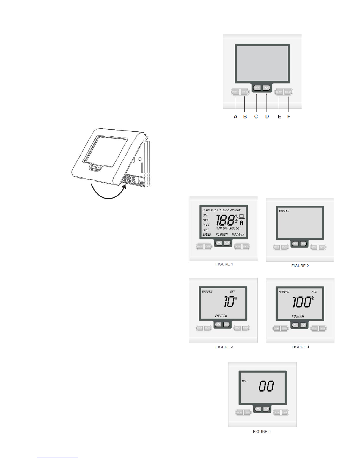
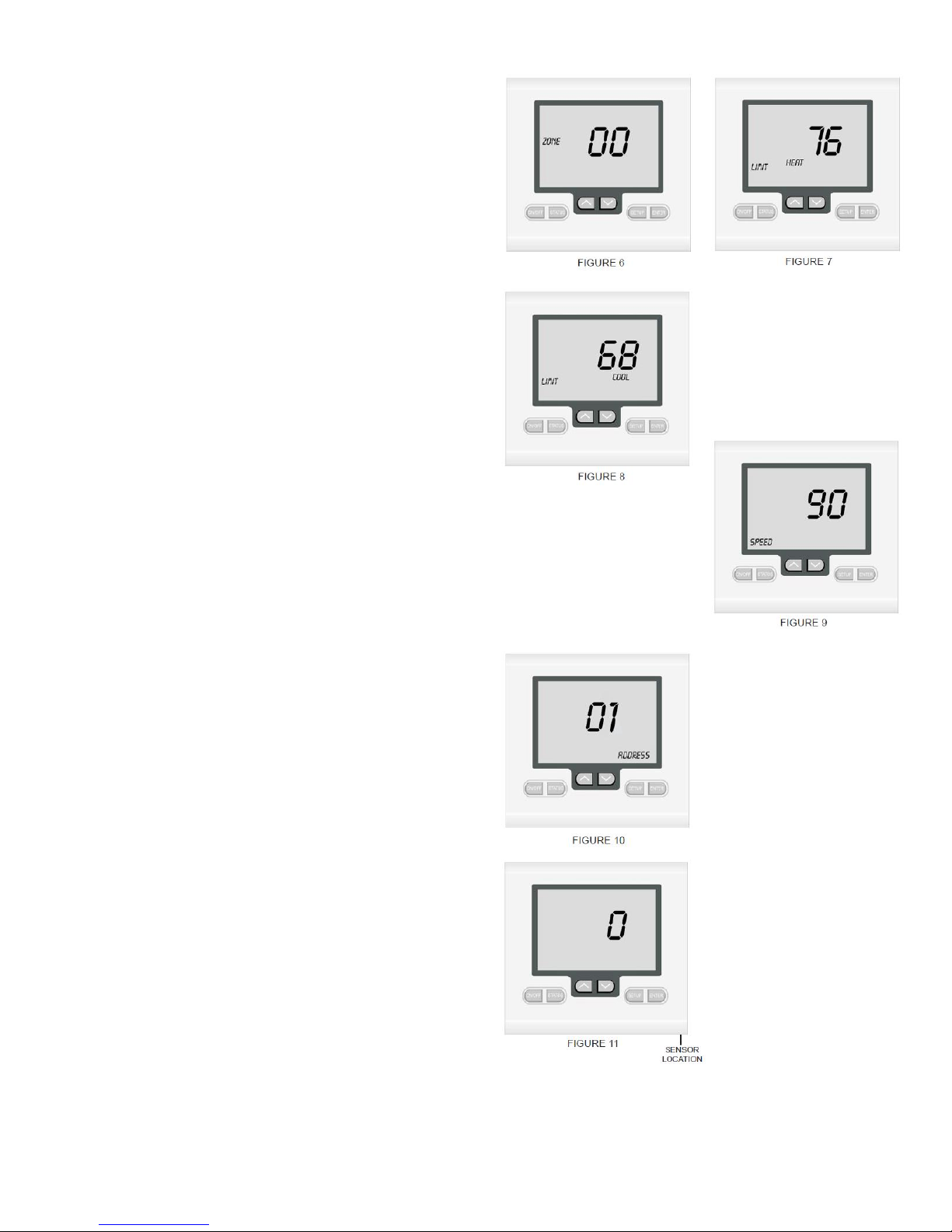
SETTING A ZONE NUMBER
Press the SETUP key again and the LCD will display
the word ZONE. The factory default is 00. This number
can be used to identify each Z2000RT thermostat wired
to a Z2000 zone control panel or when used in multiple
stand-alone applications. Use the UP and DOWN keys
to assign a ZONE number from 00 to 99. (Figure 6)
SETTING THE HEATING LIMIT
Press the SETUP key again and the LCD will display
the heating limit. The factory default is 76° F. Press the
UP and DOWN keys to change the heating limit setting.
It is strongly recommended that the limit not be set
Above Thefactory default setting. (Figure 7)
SETTING THE COOLING LIMIT
Press the SETUP key again and the LCD will display
the cooling limit. The factory default is 68° F. Press
the UP keys to change the cooling limit setting. It is
strongly recommended that the limit not be set below
the factory default setting. Refer to Figure 8.
SETTING THE ACTUATOR SPEED
Press the SETUP key again and the LCD will display
the actuator speed. The factory default is 90 seconds
which is the time it takes the actuator to drive the
damper blade fully open or fully closed. This is a critical
step in the Z2000RT setup since the thermostat can
be used with a variety of 24 Volt actuators. If you are
unsure of the actuator speed, place the actuator in the
fully closed position and then apply 24 Volts to common
and normally open. The time it takes to drive the damper
blade fully open equals the actuator speed setting.
(Figure 9)
SETTING THE MODBUS ADDRESS
Press the SETUP key again and the LCD will display
the Modbus communications address. The factory
default is 01. The Z2000RT has integrated Modbus
communications capability for remote monitoring
and control. For more information on Modus
Communications, contact Ruskin (Figure 10).
TEMPERATURE CALIBRATION OFFSET
Press the SETUP key again and the LCD will display
the temperature calibration offset as shown on
Figure 11. The factory default setting is 0. Typically,
it is not necessary to adjust the temperature calibration
offset as the Z2000RT has been factory calibrated.
If calibration is necessary, a high quality electronic
digital thermometer must be used. Place the
thermometer sensor probe next to the thermostat
sensor and allow five minutes before comparing
the temperature readings. Use the UP and
DOWN keys to adjust the temperature calibration.
The range is +/- 9° F.
6

SAVING SETTINGS AND EXITING THE SETUP MENU
Press the ENTER key and the Z2000RT will save
the setup menu settings and exit the program. The LCD
will display the space temperature along with other
normal operating functions. To review the thermostat
settings, simply press and hold the SETUP key until the
setup menu is displayed and then toggle through the
settings. Press the ENTER key to exit the setup menu.
Remove the thermostat from the sub-base and set
Switch 1 in the ON position to lock the thermostat which
will prevent setup changes from being made. When the
thermostat is locked, a padlock icon will be displayed
on the LCD as shown on Figure 12.
HELPFUL HINT
If it is necessary to exit the setup menu
before all setup functions are completed, simply
press the ENTER key and all settings will be saved.
To re-enter the setup menu, press and hold the
SETUP key until the word DAMPER appears and
then continue pressing the SETUP key to toggle through the
functions to where you left off
CHECKING THERMOSTAT STATUS POINTS
After the thermostat is locked and operational, its status
functions can be checked by pressing the STATUS key
twice and toggling through the following status points:
UNIT - Displays the HVAC unit number assigned to
thermostat.
ZONE - Displays the thermostat zone number.
DUCT - Displays the duct temperature.
DAMPER - Displays the damper position in one degree
increments. (0% = fully closed and 100% = fully open)
THERMOSTAT OPERATION
The Z2000RT is designed to provide accurate but simple
temperature control for the user. When the thermostat is not
calling, only the space temperature is displayed on the LCD
along with the padlock icon that confirms the thermostat setup
functions cannot be changed. The user can use the UP and
DOWN keys to change the thermostat setpoint within the
setpoint limits and review the status points by pressing the
STATUS key (Figure 13).
CHANGING THE SETPOINT
When the UP and DOWN keys are pressed, the thermostat will
display the word SET. The setpoint then can be changed within
the setpoint limits (Figure 14).
CALL FOR HEATING
When the thermostat calls for heating,
the word HEAT will be displayed on the
LCD as shown on Figure 15.
CALL FOR COOLING
When the thermostat calls for cooling,
the word COOL will be displayed on the
LCD as indicated on Figure 16
DAMPER POSITION OVERRIDE
The Z2000RT has a damper position override feature to assist
in air balancing and bypass damper setup. With the thermostat
unlocked, press twice and hold the SETUP key until the word
DAMPER appears on the LCD as reflected on Figure 17.
7

OVERRIDE TO OPEN
Press the UP and DOWN keys until the word OPEN appears on
the LCD and then press the ENTER key. The damper will drive
open and remain in the open position until the override is
cancelled. See Figure 18 for details.
OVERRIDE TO CLOSE
Press the UP and DOWN keys until the word CLOSED appears
on the LCD and press the ENTER key. The damper will drive
closed and remain in the closed
position until the override is cancelled. (Figure 19)
ADVANCED FUNCTIONS
CANCELLING THE DAMPER OVERRIDE
In order for the Z2000RT to control normal damper operation,
the override must be cancelled. Press and hold the SETUP key
until the word DAMPER OPEN or DAMPER CLOSE appears on
the LCD. Use the UP or DOWN key until only the word
DAMPER is displayed and then press the ENTER key. The
thermostat will then resume normal operation. Refer to
Figure 20.
Z2000RT SPECIFICATIONS
Input Voltage 24 VAC 50/60 Hz
Relay Rating 24 VAC @ 1Amp per relay
Operating Temperature 23° F to 122° F Operating RH 0-
95% (non-condensing)
Size 4-7/16” W x 4-1/16” H x 7/8” D LCD
Display Size 2-3/4” W x 1-7/8” H Temperature
Sensor 10K NTC type 3
Accuracy +/- 1° F @ 77° F Display
Resolution 1° F
Control Range 36° F to 96° F
Back Light Blue EL (Electro Luminescent) Back
Light Life 3,000 hours to half brightness
Communications Protocol Modbus
Approvals FCC (Part 15) (Pending) C-tick
Warranty 5 years
Copyright © 2013 Ruskin Manufacturing
The information provided in this manual is believed to be complete and accurate. Ruskin Manufacturing is a manufacturer and supplier of
equipment and, as such, is not responsible for the manner in which its equipment is used nor for infringement of rights of third parties resulting from
such use. System design is the prerogative and responsibility of the system designer.
All Rights Reserved. The product detailed in this manual is protected by a U.S. patent. Illustrations and product descriptions published are not
binding in detail. In keeping with its policy of continuous improvement, Ruskin reserves the right to change or modify designs or specifications of
products without notice or obligation.
Table of contents
Popular Thermostat manuals by other brands

Pro1 Technologies
Pro1 Technologies T631W-2 Operation manual

Venstar
Venstar T1045 owner's manual

Danfoss
Danfoss ECtemp Touch installation guide

Emos
Emos P5613 manual

Bryant
Bryant T1-PAC01-A installation instructions

Onyx Controls
Onyx Controls ONX908PIT-V1-S1-F3/B Installation and operation instruction manual